Martin williams sami khan post tensioned concret
Bạn đang xem bản rút gọn của tài liệu. Xem và tải ngay bản đầy đủ của tài liệu tại đây (16.78 MB, 327 trang )
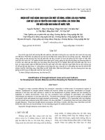
Post-tensioned Concrete Floors
Harbour Exchange, London
Post-tensioned Concrete Floors
Sami Khan
Director, Bunyan Meyer and Partners
Martin Williams
Lecturer, University of Oxford, Department of Engineering Science
and Fellow of New College, Oxford
~
,U T T
E R W O R T H
E!
N E M A N N
B u t t e r w o r t h - H e i n e m a n n Ltd
Linacre House, J o r d a n Hill, Oxford OX2 8 D P
-~A
member of the Reed Elsevier plc group
OXFORD
LONDON
BOSTON
MUNICH
NEW DELHI SINGAPORE
TOKYO TORONTO
WELLINGTON
SYDNEY
First published 1995
9 B u t t e r w o r t h - H e i n e m a n n Ltd 1995
All rights reserved. No part of this publication
may be reproduced in any material form (including
photocopying or storing in any medium by electronic
means and whether or not transiently or incidentally
to some other use of this publication) without the
written permission of the copyright holder except
in accordance with the provisions of the Copyright,
Designs and Patents Act 1988 or under the terms of a
licence issued by the Copyright Licensing Agency Ltd,
90 Tottenham Court Road, London, England W1P 9HE.
Applications for the copyright holder's written permission
to reproduce any part of this publication should be addressed
to the publishers
British Library Cataloguing in Publication Data
K a h n , Sami
Post-tensioned Concrete Floors
I. Title II. Williams, Martin
693.542
I S B N 0 7506 1681 4
Library of Congress Cataloguing in Publication Data
K a h n , Sami.
Post-tensioned concrete floors / Sami K a h n , Martin Williams.
p. cm.
Includes bibliographical references and index.
I S B N 0 7506 1681 4 (pbk.)
1. Floors, Concrete. 2. Post-tensioned prestressed concrete.
I. Williams, Martin. II. Title.
TH2529.C6K48
1995
690'.16 - dc20
94-36854
CIP
Typeset by Vision Typesetting, Manchester
P r i n t e d and b o u n d in G r e a t Britain by
H a r t n o l l s Limited, B o d m i n , Cornwall
CONTENTS
INTRODUCTION
NOTATIONS
page ix
xi
1
1
1.1
1.2
1.3
1.4
1.5
1.6
1.7
1.8
1.9
1.10
1.11
1.12
1.13
1.14
1.15
THE BASIC PRINCIPLES
Introduction
Prestressing in principle
Stress reversal
Tendons
Prestress losses
Initial and final stresses
Pre-tensioning and post-tensioning
Reinforced and post-tensioned concrete floors
Bonded and unbonded post-tensioning
Stressing stages
Construction tolerances
Fire resistance
Holes through completed floors
Post-tensioning in refurbishment
Some misconceptions about post-tensioned floors
2
5
6
7
8
9
10
14
17
18
18
18
19
20
2
2.1
2.2
2.3
2.4
2.5
2.6
MATERIALS AND EQUIPMENT
Formwork
Dense concrete
Lightweight concrete
Post-tensioning tendons
Prestressing hardware
Equipment
24
24
26
35
39
47
55
3
3.1
3.2
3.3
3.4
SLAB CONFIGURATION
General
Structural elements of a floor
Panel configuration
Span to depth ratio
61
61
64
70
74
1
vi
4
4.1
4.2
4.3
4.4
4.5
4.6
4.7
4.8
4.9
4.10
4.11
4.12
4.13
CONTENTS
PLANNING A STRUCTURE
Design objectives and buildability
Restraint from vertical elements
Dispersion of the prestressing force
Column moments
Movements in a concrete floor
Crack prevention
Tendon profile
Access at the live end
Transfer beams
Durability
Fire protection
Minimum and maximum prestress
Additional considerations for structures in seismic zones
Example 4.1
79
79
82
85
87
90
91
93
94
96
97
99
102
103
107
5
5.1
5.2
5.3
5.4
5.5
5.6
5.7
5.8
TENDON PROFILES AND EQUIVALENT LOADS
General
Equivalent load
Secondary moments
Concordance
Tendon profile elements
Composite profiles
Tendon deviation in plan
Clash of beam and slab tendons
108
108
109
112
114
114
122
129
130
6
6.1
6.2
6.3
6.4
6.5
6.6
6.7
6.8
6.9
FLEXURE IN THE SERVICEABILITY STATE
The design process
Options in a design
Computer programs
Partial prestressing
Permissible stresses in concrete
Permissible stresses in strand
Analysis
Simply supported span
Continuous spans
Example 6.1
Example 6.2
Example 6.3
Example 6.4
132
132
134
136
137
138
141
142
144
147
149
151
153
156
PRESTRESS LOSSES
General
Friction losses
Anchorage draw-in
160
160
163
164
7
7.1
7.2
7.3
CONTENTS
7.4
7.5
7.6
7.7
7.8
7.9
Elastic shortening
Shrinkage of concrete
Creep of concrete
Relaxation of tendons
Tendon elongation
Tendon force from elongation
Example 7.1
8
8.1
8.2
8.3
8.4
8.5
8.6
8.7
ULTIMATE FLEXURAL STRENGTH
Failure mechanisms
Level of prestress
Applied loads
Procedure for calculating the strength
Ultimate stresses
Strain compatibility
Anchorage zone
Example 8.1
Example 8.2
9
9.1
9.2
DEFLECTION AND VIBRATION
Deflections
Vibration
Example 9.1
Example 9.2
Example 9.3
10
10.1
10.2
10.3
10.4
SHEAR
Shear strength of concrete
Beams and one-way slabs
Two-way slabs
Alternatives to conventional shear reinforcement
Example 10.1
Example 10.2
11
11.1
11.2
11.3
11.4
11.5
11.6
SLABS ON GRADE
The design process
Factors affecting the design
Traditional RC floors
Post-tensioned ground floors
Elastic analysis
Construction
Example 11.1
12 DETAILING
12.1 Drawings and symbols
vii
168
170
171
172
173
173
174
177
177
180
181
182
185
189
191
194
197
198
198
206
213
216
219
221
222
224
230
240
244
245
249
250
251
257
259
261
267
269
271
271
viii
CONTENTS
12.2
12.3
12.4
12.5
12.6
Minimum reinforcement
Tendon spacing and position
Deflection and cladding
Movement joints
Detailing for seismic resistance
274
276
277
277
281
13
13.1
13.2
13.3
13.4
13.5
13.6
13.7
13.8
SITE ACTIVITIES AND DEMOLITION
Storage of materials
Installation
Concreting
Stressing
Grouting
Finishing operations
Demolition
Cutting holes
284
286
287
288
289
294
295
295
303
REFERENCES
INDEX
306
309
INTRODUCTION
This book deals with the design of concrete building structures incorporating
post-tensioned floors. Post-tensioning is the most versatile form of prestressing, a
technique which enables engineers to make the most effective use of the material
properties of concrete, and so to design structural elements which are strong,
slender and efficient. Design in post-tensioned concrete is not difficult and, if
done properly, can contribute significantly to the economy and the aesthetic
qualities of a building. As a result, post-tensioned floors have found widespread
use in office buildings and car park structures, and are also frequently employed
in warehouses and public buildings. However, in spite of this, most prestressed
concrete texts devote comparatively little attention to floors, concentrating
instead on beam elements. This book therefore aims to answer the need for a
comprehensive treatment of post-tensioned floor design.
The first four chapters of the book give a detailed, non-mathematical account
of the principles of prestressing, the materials and equipment used, and the
planning of buildings incorporating post-tensioned floors. The following chapters
outline the detailed design process, including numerous worked examples, and
the book concludes with chapters describing site procedures for construction,
demolition and alteration. While the reader is assumed to have a grasp of the
basics of reinforced concrete design, no prior knowledge of prestressing is
required. The book is thus suitable for use by architects, contract managers and
quantity surveyors who may wish to gain an understanding of the principles
without going into the mathematical aspects of the design process, as well as
structural engineers requiring detailed design guidance. It is also intended for use
as an educational text by students following civil engineering, architecture and
building courses.
The title of the book reflects the fact that its emphasis is on the behaviour and
design of the floors themselves. Thus, while the effect of post-tensioned floors on
other structural elements such as columns and walls is considered, detailed
guidance on the design of these elements is not given; such information can be
obtained from any one of the many excellent reinforced concrete design texts
already available. Neither does this book deal with the prestressing of building
elements other than floors, such as foundations, moment-resisting columns or
vertical hangers. These elements are comparatively rare, or are not usually
prestressed. If guidance on design of such elements is required, reference should
be made to specialist literature.
In any book on post-tensioning comparisons with reinforced concrete are
x
INTRODUCTION
inevitable. Post-tensioning offers numerous advantages, but it would be foolish
to suggest that it is the best design option in all cases. Therefore, detailed
guidance is given on the relative merits of post-tensioned and reinforced concrete
floors, and the reasons for choosing one or the other in a particular situation are
discussed.
Although the post-tensioning technique is now quite well established, research
and development activities continue to offer possibilities for future improvements,
a recent example being the development of polymer prestressing tendons. Many
of these advances require considerable further research before they are ready for
practical use. In this book such developments are discussed briefly, but the
emphasis is placed firmly on the current practice.
While the general principles and methods of prestressing are universal, detailed
design procedures usually follow national code recommendations, which vary
from country to country. For a text to be useful as a design guide, it must
necessarily make reference to national codes. In this book, full design procedures
compatible with both the British Standard BS 8110:1985 and the American code
ACI 318-1989 are described. However, the design methods are always introduced
in a way which emphasizes the principles on which they are based rather than
simply reiterating the code guidelines. While every effort has been made to
describe as fully as possible the provisions of BS 8110 and ACI 318, the book
should certainly not be regarded as a replacement of either code. The relevant
standard or code of practice should always be consulted to check specific
requirements.
As far as possible, the equations and data presented are given in SI units
followed by imperial equivalents. Extracts from BS 8110 are presented in metric
form only, since it is unlikely they will be employed in countries using imperial
units. ACI 318 formulae and data are given in both SI and imperial units.
The help of many individuals and organizations in the preparation of this book
is gratefully acknowledged. The finished diagrams were produced with the
generous assistance of the British Cement Association, Crowthorne. Most of the
photographs and some sketches were contributed by VSL International of Berne,
Switzerland. Extremely helpful comments on the manuscript were made by Pal
Chana of the Concrete Research and Innovation Centre, Imperial College; B. K.
Bardhan-Roy of Jan Babrowski and Partners; Peter Matthew of Swift Structures
Ltd; and David Ramsay of DHV Burrow-Crocker Consulting.
Extracts from BS 8110 have been reproduced by permission of the British
Standards Institution, 2 Park Street, London, WlA 2BS. Extracts from ACI 318
have been reproduced by permission of the American Concrete Institute, Box
19150, 22400 West Seven Mile Road, Detroit, Michigan 48219, USA. Copies of
the codes may be purchased from these organizations at the addresses given. The
authors are also grateful to the British Cement Association and the Concrete
Society for their permission to include extracts from their publications; to Bridon
Wire for supplying data on their products; and to Bunyan, Meyer & Partners for
their support.
NOTATIONS
The following symbols are common to all chapters. Further symbols, used
locally, are given in the relevant chapters.
hc
Ap
A~
A s,
asv
b
br
bv
C~
D
d
d~
dx
d~
dp
dr
ep
Ec
Er
Es
fob
ftci
f'c
Li
Lu
gb
ge
ft
Area of concrete section
Area of tendon steel
Area of bonded steel
Area of compression steel
Area of links per unit length of member
Width of concrete in compression
Width of concrete on tension face, rib width
width of section effective in shear, rib width for T-, I- or L-sections
Creep coefficient
Overall depth of section
Depth of tension steel from compression face
Depth from extreme compression fibre to centre of compression
Depth of rectangular stress block
Depth of neutral axis
Depth of tendon centroid
Depth of bonded rod reinforcement in tension
Eccentricity of tendon
Modulus of elasticity of concrete at 28 days
Modulus of elasticity of concrete at stressing
Modulus of elasticity of steel
Equivalent stress, assuming a rectangular stress block
Initial concrete cylinder strength
28-day cylinder strength
Initial concrete cube strength
28-day cube strength
Stress in tendon in the ultimate state
Initial stress in tendon, after immediate losses
Stress in tendon after all losses
Ultimate strength of tendon per unit area
Tendon yield stress
Stress in bonded reinforcement in ultimate state
Tensile strength of concrete
Strength of rod reinforcement
xii
fy'r
k
K
L
Lt
M
Mer
Mo
Mr
Mu
Pi
Pf
Pj
Po
Px
Pay
Pcu
Sv
V
vo
Voo
Vor
Vp
W
w
We
we
Z
Zt
Zb
#
'~m
NOTATIONS
Strength of steel used in links
Moment of inertia of concrete section
Subgrade modulus
Wobble friction coefficient, per unit length
Span length
Tendon length between anchorages
Moment
Cracking moment
Moment due to self weight of concrete section
Moment with factored load
Ultimate flexural strength
Initial tendon force, after immediate losses
Final tendon force, after all losses
Jacking force in tendon
Tendon force at anchorage
Tendon force at distance x
Average stress in concrete due to prestress
Stress in concrete compression block
Spacing of links
Ultimate shear force
Ultimate shear resistance
Ultimate shear resistance of section uncracked in flexure
Ultimate shear resistance of section cracked in flexure
Vertical shear due to prestress
Ultimate shear resistance of a reinforced, non-prestressed, section
Concentrated load or total distributed load
Load intensity
Concrete density
Equivalent load intensity
Section modulus
Section modulus for top fibre
Section modulus for bottom fibre
Ratio dc/d .
Coefficient of friction between tendon and sheath
Deflection or displacement
Partial safety factor
Poisson's ratio
Sign conventions
Positive signs apply to:
y-axis going upwards
Load acting downwards on concrete member
NOTATIONS
xiii
Support reactions acting upwards on member
Sagging moment
Compressive stress
Definitions and conversions
Rod reinforcement" bonded non-prestressed steel
Assumed relationship between cylinder and cube strength" f~, = 0.8ft,
The following approximate conversions are used"
1 metre
1 kilogram
1 kilonewton
1 newton per sq.mm
1 kilonewton per sq.mm
1 kilonewton per sq.m
1 kilogram per cu.m
(m)
(kg)
(kN)
(N/mm 2)
(kN/mm 2)
(kN/m 2)
(kg/m 3)
=
=
=
=
=
=
=
39.37
2.2
220.0
145.0
145.0
20.89
0.0625
inches
pounds
pounds
pounds per
kilopounds
pounds per
pounds per
(in)
(lb)
(lb)
sq.in
(psi)
(kip) per sq.in (ksi)
sq.ft
(psf)
cu.ft
(pcf)
This Page Intentionally Left Blank
1 THE BASIC PRINCIPLES
1.1
Introduction
Post-tensioning has been in use in floor construction for several decades now,
especially in the United States, Australia, the Far East and, to some extent, in
Europe. Its economic and technical advantages are being increasingly appreciated,
and the proportion of concrete floors being post-tensioned is growing.
In this chapter the basic principles of prestressing are explained, and the
various methods of prestressing are briefly discussed. This is followed by
comparisons between the alternative forms of using concrete as a structural
medium. It answers the questions frequently asked by those interested enough in
the subject to wish to know more about it but with no need for a detailed design
insight.
Post-tensioning is a technique of pre-loading the concrete in a manner which
eliminates, or reduces, the tensile stresses that are induced by the dead and live
loads; the principle is further discussed later in this chapter. Figure 1.1 is a
diagrammatic representation of the process. High strength steel ropes, called
strands, are arranged to pass through the concrete floor. When the concrete has
hardened, each set of strands is gripped in the jaws of a hydraulic jack and
stretched to a pre-determined force. Then the strand is locked in a purpose-made
device, called an anchorage, which has been cast in the concrete; this induces a
compressive stress in the concrete. The strand is thereafter held permanently by
the anchorage.
The non-jacking end of the strand may be bonded in concrete, or it may be
fitted with a pre-locked anchorage which has also been cast in the concrete. The
anchorage at the jacking end is called a live anchorage whereas the one at the
non-jacking end is termed a dead anchorage. To allow the strand to stretch in the
hardened concrete under the load applied by the jack, bond between the strand
and concrete is prevented by a tube through which the strand passes. The tube,
termed a duct or sheathing, may be a metal or plastic pipe, or it may consist of a
plastic extrusion moulded directly on the rope. If extruded, the strand is injected
with a rust-inhibiting grease. After stressing, the sheathing, if not of the extruded
kind, is grouted with cement mortar using a mechanical pump.
The terms tendon and cable, are the general and interchangeable names for the
high strength steel lengths used in post-tensioning---equivalent to reinforcement
in reinforced concrete. A tendon may consist of individual wires, solid rods or
ropes. It may contain one or more ropes or wires housed in a common sheathing.
2
POST-TENSIONED CONCRETE FLOORS
Except in ground slabs, tendons do not run in straight lines. They are normally
draped between supports with a shallow sag, just as a rope hangs when lightly
stretched between two supports. The geometric shape of the tendon in elevation
is called its profile; it is usually, but not necessarily, parabolic. At any point along
its length, the vertical distance between the centroid of the concrete section and
the centre of the tendon is called its eccentricity; by convention it is said to be
positive when the tendon is below the section centroid.
The requirements for concrete, rod reinforcement and formwork for posttensioning are similar to those for reinforced concrete, except for minor
differences. Early strength of concrete is an advantage in post-tensioning; the
quantity of rod reinforcement is much smaller; and the shuttering needs a hole in
the vertical edge shutter at each jacking end of the tendon, and the anchorages
need to be attached to the edge shutters. The differences in the materials, though
minor, are discussed in detail in Chapter 2. Post-tensioning also needs stressing
tendons to be made of high tensile strength; these and the associated hardware
are briefly discussed in this chapter and in detail in Chapter 2.
The basic form of a post-tensioned floor is similar to that of a reinforced
concrete floor. Slabs can be solid, ribbed or waffle; beams can be downstand,
upstand or strips within the slab thickness.
1.2
Prestressing in principle
In reinforced concrete construction, the lack of strength of concrete in tension is
compensated for by providing bonded steel reinforcement near the tension faces
of the concrete section. The steel, being strong in tension, bears the tensile forces
and the concrete takes the compressive forces. Under no-load condition the steel
is unstressed; as a reinforced concrete member is loaded it deforms, inducing
compressive and tensile stresses. The stresses in concrete and steel, therefore, vary
with the load.
In prestressing, a permanent external axial force, of predetermined magnitude,
is applied to the concrete member, which induces a compressive stress in the
concrete section. When the service load is applied, the generated tensile stress has
to overcome the compressive prestress before the concrete is driven into any
tension. The tensile strength of concrete is, therefore, effectively enhanced. The
prestressing force does not significantly change with the load within the
serviceability limit. The principle is illustrated in Figure 1.2(a).
Consider a simple beam, required to carry a downward acting imposed load; at
this stage, assume that the self-weight of the beam is negligible. An axial
prestressing force is applied at the centroid of the section, which induces a
uniform compressive stress across the section, Figure 1.2(a). At the top of the
beam, the flexural compression is added to the prestress and the concrete on the
compression face is subjected to the sum of the prestress and the flexural stress,
i.e. the concrete has a higher compressive stress than it would have without the
prestress. At the bottom of the beam, the flexural tension is in opposition to the
Split pocket
former
,~
Anchorage
casting
Reinforcement
Strand
Hydraulic
jack
Wedges
Figure 1.1 Post-tensioning of a floor
3cket former
4
POST-TENSIONED CONCRETE FLOORS
(D
t._
"O
-J
X
<~.
Z
+2.0
+4.0
+6.0
+2.0
-4.0
-2.0
+4.0
+3.0
-4.0
+1.0
H+s-
(a) Axial prestress
+2.0-3.0-1.0
I
Eccentricity D/4
+2.0 +3.0
+5.0
.v.,,
(b) Eccentric prestress
~
<
Figure 1.2 The principle of prestressing
-=
~, ~.
9
~,
.J
z
Stresses (N/mm 2)
compression from the prestress and, therefore, the stress in the concrete is lower
than the tension it would have under flexure alone.
If the external force is applied eccentrically, as shown in Figure 1.2(b), then the
compressive stress induced at the bottom of the section is higher for the same
axial force. If the eccentricity is sufficiently large, the top of the beam develops a
slight tension. When the imposed load is applied to such a beam, its top fibre is
subjected to the difference between the flexural compression and the tension from
prestress. Thus the flexural compression must overcome the prestress-induced
tension before the concrete goes into compression. The bottom of the beam
remains in compression.
An eccentrically applied force, therefore, increases the capacity of the section
for flexural tension at the bottom and for compression at top. It is much more
efficient than an axial prestress. The apparent enhancement in stress capacity of
concrete allows a smaller concrete section to be used than is possible in reinforced
concrete. Prestress is generally applied eccentrically, except in very special
circumstances.
The advantage can perhaps be best illustrated by the numerical values shown
in Figure 1.2. The applied load produces a compressive stress of + 4.0 N/mm 2 at
the top and a tensile stress of - 4 . 0 N/mm2 at the bottom. With an axial prestress
of 2.0 N/mm 2 the combined net stresses would be + 6.0 N/mm 2 and - 2.0 N/mm 2
at top and bottom respectively, Figure 1.2(a).
If the same prestressing force is applied eccentrically then a moment is induced,
whose magnitude is the product of the prestressing force and its eccentricity.
Assuming an eccentricity of one-quarter of the member depth, the moment
produces flexural stresses of - 3 . 0 N/mm 2 tension at the top and + 3.0 N/mm 2
THE BASIC PRINCIPLES
5
compression at the bottom. These combine with the axial compression of
+ 2 . 0 N / m m 2 to produce prestress stresses of - 1 . 0 N / m m 2 at top and
+ 5.0 N/mm 2 at bottom. The final stresses, due to prestress and applied load, are
now + 3 . 0 N / m m 2 compression at top and + l . 0 N / m m 2 compression at
bottom, Figure 1.2(b).
With a D/4 eccentricity (where D is the depth) the stress due to prestress alone
has increased from + 2.0 N/mm 2 to + 5.0 N/mm 2 at bottom, the ratio of maximum to average stress being 2.5. This ratio is dependent on the shape of the section and the eccentricity. Ratios in the range of 2.5 to 4.0 are commonly achieved.
Note that with eccentric prestress both final stresses (top + 3.0 N/mm 2 and
bottom + 1.0 N/mm 2) are less than they would have been without prestress
( + 4 . 0 and - 4 . 0 N/mm 2 respectively). In fact, the bottom fibre is still in
compression and, for a final tension of - 2.0 N/mm2 as in the axially prestressed
case, the prestressing force can be reduced by 60%.
In floors, the level of compression due to prestress is usually in the range of 1.0
to 5.0 N/mm 2 (150 to 700 psi), the average being around 3.0 N/mm 2 (450 psi).
The lower levels of stress are generally used in ground slabs and the higher in
post-tensioned beams. This range is quite low compared with that in, say, bridges
where the average stress may be much higher, because of the longer spans and the
higher loads.
1.3
Stress reversal
In continuous structures, if the self-weight of the floor is small compared with the
applied loads or if there is a wide variation in span lengths, then it is possible for
the load-induced stresses in a span to be reversed under a certain load
combination; the stress at the bottom in the middle of the span may be
compressive and at the top it may be tensile. In such a member in reinforced
concrete, sufficient tension steel would be provided on each face to cope with the
reversal. Reinforcement at each face would be designed independently of the
reverse moment because the two conditions cannot exist simultaneously.
Consider what happens if the applied load is reversed in a prestressed member.
Taking the example in Figure 1.2(b), assume that the reverse load produces a
tension of - 4 . 0 N/mm 2 at the top and a compression of +4.0 N/mm 2 at the
bottom. The final stresses in this case would be as given in Table 1.1.
In the absence of any prestress, the flexural stresses for the reverse load (acting
upwards) would be - 4 . 0 N/mm 2 at top and +4.0 N/mm 2 at bottom; with
prestress they are - 5.0 and + 9.0 N/mm 2 respectively. Clearly, this prestressed
member is worse off with the reverse loading.
The problem is caused by the high eccentricity, which induces a tension on the
top face. This tension gets added to the flexural tension of the reverse load. With a
lower eccentricity the stresses under the reversed load are also lower, though the
stresses under the normal load would increase. In this example the reverse load is
equal in magnitude to the normal load and so the best results would be obtained
6
POST- TENSIONED CONCRETE FLOORS
Table 1.1 Effect of load reversal
Normal load
Top
Btm
Reversed load
Top
Btm
Prestress
+
Bendin9
=
Final
- 1.0
+5.0
+
-
4.0
4.0
=
=
+ 3.0N/mm 2
+1.0
- 1.0
+ 5.0
+
4.0
4.0
=
=
- 5.0N/mm z
+ 9.0
with an axially applied prestress. If the prestress produced a uniform compression
of + 2.0 N/ram 2 over the whole section then the final stresses would be - 2.0 and
+6.0 N/ram 2 in each case, as in Figure 1.2(a). This is an improvement on the
eccentrically applied prestress but not an efficient use of materials.
This clearly illustrates that prestressing is not so effective when reversal of load
is involved. Fortunately, load reversal seldom occurs in building floors and when
it does, the dead load is usually sufficient either to keep the net load still acting
downwards, or to greatly reduce the effect of the reverse loading. In continuous
spans, of short length carrying heavy live loads, such as in warehouses, the dead
load may not be large enough to avoid stress reversal and, therefore, reversal may
be a critical condition. In such cases, a reduced eccentricity of prestress provides
the better solution.
1.4
Tendons
In prestressed structures, the external prestressing force is generally applied by
stretching steel rods, wires or ropes (strand) against the concrete section, which
goes into compression. The high strength steel rods, wires, or strands are
collectively called tendons or cables. In post-tensioned floors, however, use of
strand is now almost universal.
The term strand can be rather confusing--it applies to the rope consisting of a
number of individual wires wound together, it does not mean the individual wire
comprising a rope. A typical strand consists of 7 wires wound into a rope; the
commonly used sizes are nominal 13 mm and 15 mm (0.5 and 0.6 in) in diameter.
The actual sizes and strand characteristics are given in Chapter 2.
In post-tensioning, because the prestress is applied after the concrete has
gained sufficient strength, bond cannot be allowed to develop between the
concrete and the tendons before stressing, and therefore, the tendons are housed
in a bond-breaking duct or sheathing. More than one wire or strand may be
housed in one common duct; the group of one or more is also called a tendon or cable.
The strand is similar to rod reinforcement with regard to its modulus of
elasticity and coefficient of thermal expansion but it is about four times stronger
than reinforcement steel. Strand may have an ultimate strength of 1860 N / m m 2
THE BASIC PRINCIPLES
7
(270 ksi) compared with 460 N/mm 2 (67 ksi) for rod reinforcement. At service
loads the strand may have a stress of l l 0 0 N / m m 2 (160 ksi) while rod
reinforcement may carry only about 250 N/mm 2 (36 ksi).
In addition to the tendons, some bonded rod reinforcement is also provided in
post-tensioned floorsmaround the anchorages, in the slab as ties, as secondary
reinforcement, or if needed to achieve the required ultimate strength.
The weight of steel (strands and rod reinforcement) required in a post-tensioned
floor is typically only half, or less, of that needed in a reinforced concrete floor.
Those used to working with reinforced concrete are surprised on their first visit to
a post-tensioned floor site because there is so little steel. Instead of heavy ~
reinforcement bars spaced at 150 mm centres, they see a couple of 15 mm strands
every metre or so.
Strand being so much stronger than rod reinforcement, the question arises as
to why it is not used in reinforced concrete. At a working stress of 1100 N/mm 2,
the average tensile strain in the strand would be approximately 0.0056. If used as
non-prestressed bonded reinforcement, the cracks in concrete resulting from this
strain may approach 1.0 mm in width, which would be unacceptable. To limit the
cracks to acceptable widths the strand would have to be used at a much reduced
and inefficient stress level. In prestressing, the tension in the tendon is used to
induce compression in the concrete and, therefore, advantage can be taken of its
relatively high strength.
1.5
Prestress losses
In prestressing, the compressive stress in the concrete due to the prestress is
maintained by the tension in the tendons, so that any change in the concrete
strain is reflected in the tendon forces and vice versa. If the tendons are released or
allowed to slip then their tensile force is lost or reduced, and the concrete
compression undergoes a corresponding loss. A similar effect occurs if the length
of the prestressed member reduces, for example due to shrinkage or creep of
concrete; the tendon length, being equal to that of the concrete member, also
reduces and some tension in the tendon (and compression in the concrete) is lost.
During the stressing of a tendon, friction between the tendon and the duct
causes a loss in the tendon force so that it reduces away from the jacking end. The
mechanical action of securing a tendon in the anchorage allows the tendon to
draw in, typically by 6-8 mm (88to 3 in), which results in a further loss in the
tendon force. Also, as each successive tendon in a member is stressed, the length
of the concrete member reduces by a small amount, with the consequence that the
previously stressed tendons lose some tension. In addition to these immediate
losses, post-tensioned concrete undergoes a gradual reduction in length because
of shrinkage and creep, which in theory continues for its life, though a significant
proportion of it occurs within the first few weeks. Steel tendons also undergo
long-term creep elongation (called relaxation) but of a smaller magnitude. These
actions cause a long-term loss in the tendon force.
8
POST-TENSIONEDCONCRETE FLOORS
The losses can be seen to occur in three distinct stages.
9 The prestressing force is at its maximum when a tendon is being stressed and
before it is anchored. Friction reduces the force away from the jacking end. The
previously stressed tendons, of course, undergo a loss due to elastic shortening
of concrete as each successive tendon is stressed.
9 When the tendon is anchored then the draw-in causes an immediate loss in
prestress.
9 Shrinkage and creep of concrete, and relaxation of steel, cause a further loss but
this is long term.
The magnitude of losses depends on many factors, such as the concrete
properties, the age at which the prestress is applied, the average prestress value,
the length of the tendons and the tendon profiles.
1.6
Initial and final stresses
The loss in prestress arising from friction, anchorage draw-in and immediate
elastic shortening of the member is termed initial loss. The total long-term loss is
called final loss; it includes the initial loss and the losses due to shrinkage and
creep of concrete, and relaxation of strand.
As eccentric prestress is applied to a member, the member tends to deflect
upwards so that its self-weight is borne by the prestress. In fact, prestress almost
never acts alone; it is accompanied by the self-weight of the member producing
stresses opposite to those of the prestress.
In the example shown in Figure 1.2, no allowance was made for losses. Assume
a 5% loss due to anchorage draw-in and a further 15% thereafter. Also, assume
that the self-weight of the floor induces stresses of _ 1.6 N / m m 2 and that the
imposed load produces a further _ 2.4 N / m m 2. The stresses at various stages are
shown in Table 1.2
Note that the bottom of the section is in compression at jacking and initial
stages; as load is applied the compression reduces. If the applied load is further
increased then the bottom of the member may go into tension. Often, the highest
compressive stress exists at the bottom of the section at the jacking or initial
Table 1.2 Initial and final stresses
Stage
Top/btm
Jacking
Top
Btm
Top
Btm
Top
Btm
Initial
Final
Prestress
- 1.00
+ 5.00
-0.95
+4.75
-0.81
+ 4.04
Self-wt
+
+
+
-
1.60
1.60
1.60
1.60
1.60
1.60
Imposed
+ 0.00
+ 0.00
+0.00
+0.00
+ 2.40
- 2.40
Net stress
=
=
=
=
=
=
+ 0.60
+ 3.40
+0.65
+ 3.15
+ 3.19
+ 0.04
THE BASIC PRINCIPLES
9
stage, and this occurs at an early stage in the life of the concrete when it is not
mature. In such cases post-tensioned floors can be considered to have been
load-tested during construction.
The situation is reversed at the top of the section; if the self-weight is small then
the top fibre may be in tension initially, and would go into compression as further
load is imposed. Therefore, the initial and final stresses represent two extremes in
the serviceability loading of a post-tensioned floor. Stresses are computed for
both stages in design and are generally required to be within prescribed limits.
For the initial stage the load consists of only the self-weight of the member; no
other imposed load is considered. At the final stage, the various loads are
combined, in accordance with the national standard, to arrive at the most
adverse condition.
1.7
Pre-tensioning and post-tensioning
The tendons can be stressed either before casting the concrete or after the
concrete has been cast and has gained some strength. In pre-tensioning the wires
or strands are stressed against external anchor points (or sometimes against the
mould) and concrete is then cast in direct contact with the tendons, thus allowing
bond to develop. When the concrete has gained sufficient strength, the tendons
are released from the temporary external anchorages, thereby transferring the
force to the concrete, inducing a compressive stress in it. The tension in the
tendons and the corresponding compression in the concrete is then solely
dependent on bond between concrete and tendon, and no other mechanical
device is used.
Pre-tensioned tendons usually run in straight lines. In order to deviate from
this, external deflecting devices are needed. With them, a profile consisting of a
series of straight lines can be obtained. These devices slow down the manufacturing
process and they add to the costs. The requirement for external temporary
anchors and the problems in profiling the tendons make pre-tensioning difficult
for application in situ. The process is almost exclusively confined to precasting,
and is not discussed any further.
In post-tensioning, concrete is not allowed to come in contact with the tendons.
The tendons are placed in ducts, or sheaths, which prevent bond, and concrete is
cast so that the duct itself is bonded but the tendon inside remains free to move.
When the concrete has gained sufficient strength the tendons are stressed directly
against the concrete and they are mechanically locked in anchorages cast at each
end. After this stage, tension in the tendons, and hence the induced compression
in the concrete, is maintained by the anchorages.
In bonded post-tensioning the duct is grouted after the tendons have been
stressed, so that the stressed tendons become bonded. In unbonded post-tensioning,
as its name implies, the tendons are never bonded. A detailed comparison
between bonded and unbonded systems is given in Section 1.9.
10
POST-TENSIONED CONCRETE FLOORS
1.8
Reinforced and post-tensioned concrete floors
Reinforced concrete technology is widely available and is well understood.
Post-tensioning is an advance on reinforced concrete technology and it is often
discussed in the context of reinforced concrete.
1.8. 1
General
Post-tensioning offers some very useful technical and economic advantages over
reinforced concrete, particularly for long spans, where control of deflection is
desirable, or if construction depth must be minimised. It is, however, not the best
solution in all circumstances and the various alternative forms of construction
should be carefully considered for each structure before making the choice.
For post-tensioning, it is important to consider availability of the hardware
and the technical expertise required. Excepting very special design objectives,
post-tensioning is unlikely to be economical for short spans. Often a combination
of post-tensioning and another form of construction offers a good solution. For
example, in a floor consisting of rectangular bays, if the short span is small
enough, the best solution may be to span the slab in the long direction in
post-tensioned concrete and use reinforced concrete beam strips in the short-span
direction.
Economy of construction varies from one site to the next, depending on
accessibility and availability of material and labour, and of course on the design
loading and constraints that may be imposed by other disciplines, such as a
restriction on the depth of the structure. It is, therefore, not possible to give a
general cost comparison between the two forms of construction. The authors
have found that for span lengths of about 9 m (30 ft) the cost of a floor carrying a
superimposed load of 5 kN/m 2 (100 psf) is similar in reinforced and post-tensioned
concretes. Post-tensioned concrete is more economical than reinforced concrete
above this span length. In cases of restricted floor depth or high loads, the span
length for equal costs may be as low as 7.5 m (25 ft). Further savings result from
the lighter weight and lesser construction depth of the post-tensioned floor.
For reinforced concrete, only the ultimate strength calculations are normally
carried out and deflection in the serviceability state is deemed to be satisfied by
confining the span-to-depth ratio within limits prescribed in the national
standards. Only in rare cases is it necessary to calculate deflections. Crack control
is usually governed by.deemed-to-satisfy rules for bar spacing.
In post-tensioned concrete design, serviceability calculations are carried out
for the initial and final loading conditions, for deflection and cracking, and the
ultimate strength is checked after this. Structural design of prestressed concrete,
therefore, requires more effort.
The shallow depth of a post-tensioned floor is a particular advantage in
multistorey buildings; in some cases it has been possible to add an extra floor
where there was a restriction on building height. Even where there is no such
restriction, the reduced building volume generates savings in the cost of services