the hydraulic trainer volume 1 ( basic principles components of fluid technology )
Bạn đang xem bản rút gọn của tài liệu. Xem và tải ngay bản đầy đủ của tài liệu tại đây (33.95 MB, 327 trang )
'.
~mannesm'a;;'~
•
Rexroth
Basic Principles and Components of
Fluid Technology
The Hydraulic Trainer. Volume 1
I
Rexroth Hydraulics
~W@[J@llliJ~D©@
W@~lliJm®
u[J@lDmJ®IT
~
Basic Principles and
Components of
Fluid Technology
Instruction and Information
on the
Basic Principles and Components of Fluid Technology
Authors
H. Exner· R. Freitag· Dr.-Ing. H. Geis • R. Lang. J. Oppolzer
P. Schwab· E. Sumpf
U.Ostendorff
Hydromatik GmbH, Ulm
M. Reik
HYDAC GmbH, Sulzbach
Editor
RudiA.Lang
Mannesmann Rexroth GmbH
Issued by
Printed by
lithography
Photographs and Diagrams
Issue
MannesmannRexrolhAG
0-97813lohla MaIO
JahnslraBe3·5·0·97816lohraMain
Telefon +49/09352118-0
Telefax +49109352118·3972
Telex
689418n'd
SChIeunungdflKl:: GmbH
Utertstra8e27
0·97828 Marktheidenfeld am Main
MaIOTeam Chemtegraphlsme GmbH
Goldbachelstla6e 14
0-63739 Aschatlenburg
8rueninghaus Hydromatlk GmbH, Horb and Elchmgen
HYDAC GmbH, Sulzbach
Mannesmann Rexroth AG, lohr a. Main
RE 00 301/1978
RE 00 290110.91
{lSI issue, 1978}
(2nd issue, 1991)
IS8N 3·8023·0266-4
C 1991 by Mannesmann ReXlothAG
All rights reserved-subjecl to revision.
Preface
Hydraulics is a relatively new technology used in power transmission, which may be adapted to
market requirements.
The use of hydraulic drives, as well as hydraulic open loop and closed loop control systems has
gained in importance in the field of automation. Nowadays, it is unusual to find an automatic production procedure which does not use hydraulic components.
However, in spite of the wide range of applications, there are still many more to be found. Hence,
manufacturers are expanding their experience by referring to literature and attending training
courses.
This manual Basic Principles and Components of Hydraulics (from the series The Hydraulics
Trainer) should aid you in gaining knowledge of hydraulics systems. It is not only intended to be
used as a training text, but also as an aid to the hydraulics system operator.
This trainer deals with the basic principles and functions of hydraulic components. Relationships
between functions are clarified by means of numerous tables, illustrations and diagrams. This
manual is therefore an invaluable reference aid for everyday work.
This manual is the result of collective work by a group of authors, to whom we are most grateful.
We would also like to thank Mr Rudi A. Lang, who acted as project manager and editor. In addition, Mr Herbert Wittholz must be thanked for his careful proofreading of the chapter on basic
principles and also for his many useful comments.
Mannesmann Rexroth GmbH
Lohr a. Main
Contents
Preface...
Contents
5
Chapter 1
Basic Principles
Rudi A. Lang
1
1.1
1.2
1.2.1
1.2.2
1.3
1.
2
2.1
2.1.1
2.1.2
2.1.3
2.2
2.2.1
2.2.2
2.2.3
2.3
2.3.1
2.3.2
2.4
2.4.1
2.4.2
2.4.2.1
2.4.2.2
2.4.2.3
2.4.3
2.4.3.1
2.4.3.2
2.4.3.3
2.4.3.4
3
3.1
3.2
3.2.1
3.2.2
3.2.3
3.2.4
3.3
Introduction...
Fluid technology...
Hydro-mechanics
Hydrcrstatics.....
Hydro-kinetics...
Types of energy ',ar15'e" (cho;"e)
Parameters, symbols, units...•,
Physics terms...
Mass, force, pressure.....
Mass...
Force...
Pressure...
energy, power.....
Energy...
Power....
Velocity, acceleration
Velocity
Acceleration
Hydro-mechanics
Hydro·statics....
Pressure...
Pressure due to external forces
Force transmission
Pressure transmission
Hydro-kinetics...
Flow law....
Law of conservation of energy... ..
Friction and pressure losses...
Types of flow...
Hydraulic systems...
Important characteristics of hydraulic systems...
Design 01 a hydraulic system
Energy conversion...
.
Control of energy......
Transport of energy
Further information...
Design of a simple hydraulic system...
.
23
23
23
23
24
24
.
.
.
<,
.
.
.
26
26
26
26
26
27
.
.
.
.
.
.
.
.
..
..
.
.
.
.
..
.
..
27
28
28
28
28
28
28
28
29
29
30
30
30
31
31
32
33
33
33
33
33
33
33
34
Chapter 2
Symbols to DIN ISO 1219
Rudi A. Lang
1
2
2.1
2.2
2.3
3
3.'
3.2
3.3
3.4
3.5
4
5
Basic symbols I function symbols I operational modes...
.
Energy transfer and storage...
Hydraulic pumps and motors...
Hydraulic cylinders...
Accumulators....
Open and closed loop control of energy...
.
Directional valves/continuously variable valves (modulating valves}...
Check valveslisolaling valves...
..
Pressure control valves...
Flow control valves...
2-way cartridge valves (logic elements)...
Fluid storage and preparation...
Measuring devices and indicators.....
...,...
.
.
.
.
39
42
42
42
42
43
43
43
44
44
44
45
45
.
.
. . .. .
.
.
.
.
.
Chapter 3
Hydraulic Fluids
.....Eberhard Sumpf
1
2
2.1
2.2
2.3
2.4
2.5
2.6
2.7
2.8
2.9
2.10
2.11
2.12
2.13
2.14
2.15
2.16
2.17
2.18
2.19
2.20
2.21
2.22
2.23
2.24
2.25
2.26
2.27
3
4
Introduction...
Fluid requirements...
Lubrication and anti·wear characteristics...
Viscosity... .
Viscosity index...
Behaviour of viscosity with respect to pressure ..
Compatibility with different materials...
Stability against shearing... .
.
Stability against thermal loads...
.
Stability against oxidation...
.
Low compressibility...
Little expansion due to temperature...
Little formation of foam.... .
Low intake of air and good release of air...
High boiling point and low steam pressure...
High density......
Good thermal conductivity...
Good di-electric (non-conducting) characteristics...
Non-hygroscopic... ..
Fire-resistant - does not burn...
.
Non-toxic as a fluid, as vapour and after decomposition
Good protection against corrosion...
No formation of sticky substances...
Good filtration capability....
Compatible and exchangeable with other fluids.....
Formation of silt...
User-friendly servicing... .
Eccologically acceptable...
Cost and availability... .
Summary of common fluids...
.
Example of selection of suitable hydraulic components
.
.
..
.
.
.
.
.
.
.
..
..
.
.
.
.
.
.
.
.
.
.
.
47
48
.48
49
49
49
49
49
49
49
50
50
50
50
50
50
51
51
51
51
51
51
51
51
52
52
52
52
52
53
54
Chapter 4
Hydaulic Pumps
Rudhard Freitag
1
2
2.1
2.2
2.3
2.4
2.5
2.6
2.7
2.8
2.9
2.10
3
4
4.1
4.2
4.3
4.4
4.5
Introduction
Basic design
External gear pump
Internal gear pump
Ring gear pump...
Screw pump
Single chamber vane pump
Double chamber vane pun'p
Radial piston pump
eccentric cylinder block
Radial piston pump with eccentric shaft
Axial piston pump in bent axis design
Axial piston
in swashplate design
Selection
Functional Descriptions
Screw pumps
External gear pumps...
Internal gear pumps
Radial piston pumps
Vane pumps
:"1 •••••••••••••••••••••••••
..
.
57
58
58
58
58
58
59
,"
59
59
60
60
61
61
61
62
63
64
66
Chapter 5
Hydraulic Motors
Rudhard Freitag
1
2
3
3.1
3.2
3.2.1
3.2.2
3.2.3
3.2.3.1
3.2.3.2
3.2.4
3.2.4.1
3.2.4.2
Introduction
Basic design
Functional desciptions
Gear motors
LSHT motors (slow speed motors)
Epicyclic gear motors with central shafts
Epicyclic gear motors with drive shafts
Basic principle of multi-stroke piston motors
Multi-stroke axial piston motors with rotating housing
Multi-stroke axial piston motors with rotating shaft
Multi-stroke radial piston motors
Radial piston motors (single stroke) with internal eccenler.
Variable displacement radial piston motor~...
.
75
75
77
77
78
78
80
81
82
84
85
87
90
Chapter 6
Axial Piston Units
Udo Ostendorff
1
1.1
2
2.1
2.2
3
3.1
3.2
3.3
3.4
3.5
3.6
3.7
3.8
'leg
3.10
3.11
Introduction
93
Bent axis
Swashplate
Components
Fixed displacement motors and pumps - bent axis design
Variable displacement motors in bent axis design for open and closed loop circuits
Variable displacement pump in bent axis design for open loop circuits
Variable displacement pump in bent axis design for universal applications
Variable displacement pump in swashplate design suitable for use in
medium pressure range in open loop systems
Variable displacement pump in swashplate design suitable for use in
simple mobile applications in closed loop systems
Variable displacement pump in swashplate design suitable for use in
mobile applications in open loop systems
Variable displacement pump in swashplate design suitable for use in
high pressure mobile gears in closed loop systems
Variable displacement pump in swashplate design suitable for use in
industrial applications in open loop systems
Variable displacement pump in swashplate design suitable for use in
.
industrial applications in closed loop systems ..
Summary of common adjustment methods in axial piston units
96
102
106
108
109
110
113
113
114
114
115
116
116
117
Chapter 7
Hydraulic Cylinders
Paul Schwab
1
2
2.1
2.2
2.3
3
3.1
3.2
4
5
5.1
5.2
6
6.1
6.2
7
7.1
7.2
Cylinders in hydraulic circuits
Types of cylinders with respect to functions
Single acting cylinders
Double acting cylinders
Special types of single and double acting cylinders...
Basic design
Tie rod cylinder
Mill type cylinder
Types of connection and notes on installation
:
Buckling...
.
Buckling without side loading
Buckling with side loading
Cushioning
Cushioning at cylinder base
Deceleration force
Servo cylinder systems
Servocylinder.
Servo manifold
.
123
123
123
124
125
127
127
130
135
139
139
140
140
140
140
141
141
144
11
Chapter 8
Rotary actuators
Paul Schwab
1
2
2.1
2.2
2.3
2.4
2.5
GeneraL ..
~
.
1~
Rotary piston/rotary actuator...
.
Parallel piston/rotary actuator...
.
In-line piston/rotary actuator with connecting rod drive
In-line piston/rotary actuator with rack and pinion drive
148
148
149
149
Chapter 9
Accumulators and Accumulator Applications
Martin Reik
1
2
2.1
...??
2.3
2:4
2.5
2.6
2.7
3
3.1
3.2
3.3
3.4
4
4.1
4.2
4.3
4.4
5
5.1
5.2
5.3
5.4
5.5
5.6
6
General...
.
Function...
.
Energy storage...
Fluid reserve...
.
Emergency operation...
.
Compensation of forces...
.
.
Compensation of leakage oil...
.
Damping of shocks and vibrations...
Separation of fluids...
Gas accumulators with separating element...
Bladder accumulators...
Membrane accumulators ..
Piston accumulators
.
.
Addition of pressure containers...
Accessories for hydro-pneumatic accumulators
Safety and isolating control blocks...
.
Filling and testing pro"eoure'
Nitrogen charging
Fixing elements...
.
Design of hydro-pneumatic accumulaotrs with separating element... ..
Definition of operational parameters...
.
Change of state in a gas...
.
Determination of accumulator size...
.
Deviations from ideal gas behaviour...
.
Design procedure...
.
Selection of type of accumulator for typical applications
Safety regulations
151
152
152
156
156
158
159
159
162
164
165
165
166
166
167
167
.
.
.
.
.
.
169
170
171
171
172
173
173
175
175
175
13
Chapter 10
Non Return Valves
Dr. Harald Geis, Johann Oppolzer
1
2
3
3.1
3.2
3.3
3,4
4
General
Simple non return valves
Pilot operated check valves
Model withoulleakage port (valves,
SV)
Model with leakage port (valves, type ~L}
Applications using pilot operated check valves, types SV and SL.
Pre-fill valves
2-way cartridge valves (logic elements)
':'
179
180
182
182
.
185
186
187
Chapter 11
Directional Valves
Dr. Harald Geis, Johann Oppolzer
1
1.1
.,!.2
1.3
1.4
2
2.1
2.1.1
2.1.2
2.1.3
2.2
2.2.1
2.2.2
2.2.3
2.3
3
4
4.1
4.2
4.3
5
6
6.1
6.2
,
General...
.
Operation and function
Special characteristics
Directional valve power
Types of directional valves
Directional spool valves
Direct operated directional spool valves
Electrical operation...
Mechanical, manual operation
Fluid operation (hydraulic or pneumatic)
Pilot operated directional spool valves
Spring centred model
Pressure centred model
Pilot oil supply
Leak free directional spool valves....
.
Rotary directional spool valves
Directional poppet valves
Direct operated directional poppet valves
Pilot operated directional poppet valves
Symbols
Comparison of directional spool valves with directional poppet valves
Design notes for the selection of a valve size
Dynamic performance limit
Pressure difference in directional valves ,
..
189
189
189
191
192
193
194
194
196
196
197
198
198
200
201
202
203
203
205
208
209
210
210
211
15
Chapter 12
Pressure Control Valves
Dr. Harald Geis, Hans Oppolzer
1
2
2.1
2.2
2.3
2.4
2.5
3
3.1
3.1.1
3.1.2
3.1.3
3.1.4
3.2
3.2.1
3.2.2
4
4.1
4.2
04.3
4.4
4.5
4.6
Introduction...
Pressure relief valves...
.
Task...
.
Function....
.
Direct operated pressure relief valves, type DBD
Pilot operated pressure relief valves
Technical data...
.
Pressure sequence valves
Sequence valves...
.
Direct operated sequence valves, type OZ.O..... .
Pilot operated sequence valves, type OZ
Sequence valve with internal drain...
.
Sequence valve with external drain
Accumulator charging valves...
.
Pilot operated accumulator charging valves, type OA
Pilot operated accumulator charging valves, type OAW
Pressure reducing valves
Task.....
.
Function...
.
Direct operated pressure reducing valves, type OR.O
Pilot operated 2-way pressure reducing valves, type OR
Pilot operated 3-way pressure reducing valves, type 3DR
Technical data...
.
.
213
214
214
214
215
216
220
226
226
226
227
228
228
230
230
231
232
232
232
232
234
236
237
Chapter 13
Flow Control Valves
Dr. Harald Geis, Johann Oppolzer
1
2
2.1
2.1.1
2.1.2
2.1.3
2.1.4
2.1.5
2.2
3
3.1
3.2
3.2.1
3.2.2
3.2.3
3.3
General..-....
Throttle valves...
.
Viscosity dependent throttle valves..
.. .
Pipe mounted throttle valves...
.
Throttle valves for sub-plate mounting and flange connection
(may also be installed directly into pipes)
Throttles and throttle check valves for manifold mounting
Throttle check valves for sandwich plate mounting
Deceleration valves...
Throttle valves independent of viscosity...
Flow control valves... .
GeneraL..
2-way flow control valves...
.
Upstream pressure compensators...
Downstream pressure compensators...
..
Application of 2-way flow control valves...
3-way flow control valves...
.
241
244
244
244
.
.
....
.
.
.
.
245
246
247
248
249
250
250
250
250
252
253
254
17
Chapter 14
Filters and Filtration Technology
Martin Reik
1
2
2.1
3
3.1
4
4.1
4.2
4.3
4.4
5
5.1
5.2
6
7
8
8.1
8.2
8.3
-8,4
8.5
8.6
8.7
9
9.1
9.2
9.3
9.4
9.5
9.6
10
10.1
10.2
10.3
11
11.1
11.2
11.3
Basics...
Notes on design and servicing...
.
Causes of contamination...
.
Analysis of solid particle contamination...
.
Classification systems for the degreee of contamination in a fluid
Filtration process
Gravity filters...
.
Pressure line filters......
.
Centrifuges...
.
Filter presses...
Filter element material...
Surface filtration...
Depth filters...
.
Filter element design...
.
Selection of filtration rating...
Filter testing...
Verification of production quality (Bubble Point Test)... .
Colapse and burst pressure test...
.
Test of compatibility with fluid...
Flow - fatigue characteristics of elements...
.
Determination of pressure losses dependent on flow...
Multipass test...
.
Documentation on test results...
.
Types of filter housing ..
Suction filters...
Pressure line filters...
Tank mounted return line filters...
.
Valve stacking assembly...
.
Fillers and breathers...
.
Clogging indicators...
.
Filtration systems...
.
Open loop circuit...
Closed loop circuit...
~~~~i~~t~fnfi%~~.~.t.~..t.~~.~.~.~~.~~~~~.i.t..........
Filtration design... .
Filter design criteria....
Selection of filter elements...
.
.
.
.
.
.
.
.
.
:
257
260
261
264
265
266
266
266
266
266
267
267
267
268
268
270
270
270
271
272
273
274
276
277
278
279
281
283
284
285
286
286
288
;:~
.
.
289
290
290
.
.
Chapter 15
Accessories
Martin Aeik
1
2
2.1
2.2
2.3
2.4
Introduction...
Components to reduce noise...
General...
.
Decoupling of component vibrations...
Components for the decoupling of vibrations in fluids
Components for the decoupling of noise travelling in air
.
.
..
295
295
295
295
299
299
19
3
3.1
3.2
4
4.1
4.2
5
5.1
5.2
5.3
........... 300
..................................... 300
Components for controlling fluid temperature...
The surface of the tank...
Oil-air cooler and heal exchanger...
Components to isolate flow...
Ball valve .....
Double ball valve ...
Components for control and display functions...
General ....
Display devices which are permanently installed....
Display devices which are not permanently installed ...
..... 300
...... 302
....302
·
304
·
304
·
304
..........304
..........317
Chapter 16
Connections
Herbert Exner
1
2
3
4
4.1
-4.2
4.3
4.4
4.5
5
5.1
5.2
5.3
6
6.1
6.2
Introduction...
Valves for mounting in pipe lines ...
Cartridge valves with threaded cavity...
Valves lor subplate mounting .
Standard mounting patterns
.
Individual 5ubplates .
Standard manifolds .
Control plates and control manifolds...
Adaptor plates...
Stacking assemblies ....
Vertical stacking assemblies...
Horizontal stacking assemblies...
System stacking assemblies...
Mobile control valves .
Single block design .
Sandwich design...
_ .. __ ... _ .. __ . _ .. _ .. _. __ .. _ .. _._ .. _._.
............. 319
~9
........ 319
...................320
......................320
............... 321
............. 321
............. 322
............... 322
............ 322
............. 322
............ 323
............. 323
................ 323
.................... 323
....................... 324
Chapter 17/
Small hydraulic power units
Herbert Exner
Introduction.....
Components of power units...
Small hydraulic power units for intermittent use ...
Small hydraulic power units with standard electrical motor...
.
.
327
327
328
329
.
331
337
.
.
Appendix
Summary of symbols used...
Glossary ..
.
21
Basic Principles
Chapter 1
Basic Principles
Rud] A. Lang
1.
Introduction
As this chapter describes basic principles, certain terms
from Physics must also be mentioned. It must be noted
that even though Physics used to be thought of as a
completely separate subject to Chemistry. it is now
realised that there is no clear dividing line between the
The term fluid includes liquid, steam or gases, i.e. air is
also a fluid when considered as a mixture of gases. As fluid power is concerned with the mechanical characteristics of fluids, we use the term hydro-mechanics when
we
are
dealing
with
liquids
and
aeromechanics when we are dealing with air.
1.2
Hydro-mechanics
In "hydraulic" fluid power the laws of hydro-mechanics
are used. Pressure, or energy, or signals in the form of
pressure are transferred, and the laws of hydro-statics
(mechanics
of
still
fluids)
and
of
hydrokinetics 1) (mechanics of moving fluids) apply.
two subjects. Chemistry also determines processes
which occur in tife. A link between the two subjects is the
effect of electrical or electronic actions.
Processes mentioned may very slightly from recent common hydraulics practice, however we hope that what we
describe is acceptable. Deviations from practice will be
mentioned in footnotes. Physical processes in all
technical fields will be described uniformly, due to the
"'Way we describe the processes.
1.1
Fluid power
This field was until recently described as "oil hydraulics
and pneumatics". This was not only corrected in DIN, but
the industry has also adopted the subject designation 01
"fluid power". When the tille ·oil hydraulics· appeared
many years ago, mineral oil manufacturers became
interested in it, as this subject would probably deal with
the problems in pipelines, since hydraulics was
supposed to be the science of fluid flow laws.
In fact, this subject area deals with the transfer of energy
and, when the fluid is stationary, with the transfer of
pressure. However, in the transfer of pressure, for
example, at the sam~ time as a hydraulic cylinder or
motor operates, the pump may generate a flow, and
hence the flow laws need to be considered as well.
Because of this, the term "hydraulics· has been retained
in fluid power to describe the hydraulic characteristic, as
opposed to the "mechanical" or "pneumatic"
characteristics. However, wherever possible, a phrase
such as "some hydraulics is built into the system" should
be avoided.
Care should be taken that the mechanical characteristics
of a pressure fluid, (i.e the ability 10 transfer pressure) are
made use of in fluid power systems. This is not only true
for the hydraulics in fluid power, but also for pneumatics.
1.2.1
Hydro-statics
The term hydro-stalic pressure is common in Physics. It is
the pressure which acts on the base of an o~r
filled with fluid, and which is dependent on the height 01
the head of liquid inside the container. A hydraulic
paradox occurs here, which is that the shape of the
container is irrelevant, and only the height of the head 01
liquid determines the pressure. Hence, this also means
thai the pressure at the bottom 01 the container is higher
than at the top of the container. This fact is well-known, if
you consider the pressure of water deep down in the open
sea. The behaviour is the same in a ·sea of air".
In statics, care must be taken that the forces are
balanced. This is also true for analogue forces in hydrostatics. AI the base of a container, at the bottom 01 the
sea, or at a particular height in the place to be measured,
the pressure present does not create any changes In the
existing relationships.
If the fluid is enclosed in a closed container, as for
example, in a hydraulic cylinder in fluid power, and if much
higher pressures are needed than exist due to gravity at a
certain height in a fluid, then these pressures are created
via appropriate technical measures, e.g. by a hydraulic
pump. Fluid is pumped into the closed container at a
pressure produced by the hydraulic pump, and this
1) This lield is still widely known as 'hydro-dynamics'.ln
reference english books, it used only to be called hydro·kinetics,
but recently, especially Irom American sources, hydro·
dynamics has been used instead. Here is however
recommended that hydro-dynamics be used to cover both
hydro-statics and hydro-kinetics, as stated in DIN 13317. In this
standard, dynamics covers bolh statics and kinetics, as
dynamics deals in general with forces. and not only with the
forces which are generated from kinetic energy.
23
Basic Principles
pressure exerts itself equally on all sides of the container.
This fact may be made use of, by making the base of the
container movable. The base then moves,when pressure
is applied, and providing that the hydraulic pump
continues to supply fluid under pressure, a head of liquid
is moved.
If the hydraulic cylinder (also under pressure) is at rest,
e.g. in clamping hydraulics the forces are in equilibrium.
This effect may be described as hydro-static. However, if
the piston in the cylinder is moved by a supply of flow
under pressure, then not only is the pressure produced
from potential energy effective, but a boost pressure is
also effective which is created by the kinetic energy. This
pressure must be and is taken into account in fluid power
systems. The relationships in this process or system may
not really be described wholly as hydro-static, but the
hydro-static relationships predominate.
Systems of this type, where hydro-static relationships are
predominant and the transfer of pressure is most
important, operate at relatively high pressures and low
flow velocities in order to keep the influence of hydrokinetics 1) as low as possible.
1.2.2
Hydro-kinetics
Systems in which the kinetic energy of moving fluids is
used to transfer power are not usually considered-to be
part of fluid power, even though there is no physical
reason for them not to be included. These often so-called
"hydro-dynamic drives" are the ones which as already
mentioned should really be called "hydro-kinetic drives'.
In this type of drive, as in fluid power the laws of hydrostatics must be considered as well as those of hydrokinetics, but in this case the laws of hydro-kinetics are the
predominant ones.
Considering the fact that both types of energy are active in
"hydro-dynamic drives' they must also both be active in
systems where hydro-statics is predominant. Hence
these systems are also "hydro-dynamic" systems, and so
to form sub-groups of hydro-statics and hydro-dynamics
would be incorrect.
The still so-called "hydro-dynamic drives" operate
according totheirdesignation with high flow velocities and
relatively small pressures.
~-
1.3
Types of energy transfer
Energy source
(Drive)
(choice)
Hydraulics 2)
Pneumatics 3)
Electrics
Mechanics
Electric motor
Combustion er9ne
Accumulator
Electric motor
Power supply
Battery
Electric motor
CorrOOstionengne
Pressure tank
CorrOOstionengne
Weight force
Tension force (spring)
Energy
transfer elements
Pipes and hoses
Pipes and hoses
Electrical cable,
magnetic field
Mechancal parts
Levers, shafts, etc.
Energy carriers
Ruids
AI'
Electrons
Rigid and elastic
objects
Force density
(""""'-)
Large,
high pressures,
large forces,
smaflflow
Relatively small,
low pressures
Small, with respect to
power weight
Electric motor with
hydraulic motor t : 10
Large,seIeclionarddislribtJ.
lia101requiredllowisofleo
not as good asi1 hydraulics
Smooth control (acceleration, deceleration)
Very good via
pressure and
flow
Good via
pressure and flow
Good to very good
electrical open loOp and
closed loop control
Good
Types of movement
~of outputs
Unear and
rotary movements via
hydraulic cylinders and
hydraulic motors easily
attainable
Unear and
rotary movements
via pneumatic cylinders
and pneumatic motors
easily attainable
Primarily rotary movement,
linear movement:
solenoid
small forces
short strokes,
pass. linear motor
linear and
rotary movements
....
....
Table 1: Features of types of energy transfer
see footnote on page 23
2) as part of fluid power, even though hydraulics deals with far
more than just fluid power.
1)
24
as part of fluid power, even though pneunatics deals with far
more than just fluid power.
3)
Basic Principles
1.4
Quantities, symbols, units
(see DIN 1301 part 1 and DIN 1304 part 1)
Quantity
Symbol
f
Length
Distance
51 unit
Dimension
Conversion 10 other accepatable units
Relationship
1 m"" l00cm::: l000mm
Melre
Area
A
Metre squared
m2
Volume
V
Metre cubed
m3
2
2
2
1 m "" 10000cm "" 1 000 000 mm
::106 mm 2
1
m3 ", l000dm3
1 dm3 ",1 L
t Seconds
Time
Velocity
v Metre per
second
5
1!!!.'" eOrn
S
min
Acceleration
a Metre per
m
Acceleration due to gravity (rounded oN)
m
second squared
7
Metre cubed per
second
m
g::9.81
v=.!.
I
E}
5
Flow
Qv,
0
3
s
rrin
m'
L
1-=60000min
S
n
Revolutions per
second
Revolutions per 1
minute
min
---!:.....
litre per minute
1
S
60
1
S'" rrin
(rpm)
Mass
m Kilogram
kg
lkg=l000g
Density
p
kg
Kilogram per
decimalre cubed
Kilogram per
metre cubed
~
m= V·p
kg
dm3
m
P=--v
l~"'O.OOl~
3
3
m
dm
Force
F
Newton
Pressure
p
Newton per
metre squared
~ l~""lpa=O,OOOOlba
Pascal
Pa
F
=m-a
Fa = m-g
IN'''l~
.'
1 ba =10....!!.-'" lOS..!!..
2
cm
Won.
W
Temperature in Celsius
T,
e
lJ",1Ws",lNm
1 kWh "'3,6MJ=3,6·106 WS
Joule
P Wan
Power
Temperature
Kelvin
t, 11
2
m
10-5 bar = 1 Pa
W
celsius
°C
O°C~273K
OK ~-273OC
Table' 2. Quantities, symbols and Units
25
Basic Principles
The following analogies are relevant for linear movements (hydraulic cylinders) and rotations (hydraulic
motors):
Hydraulic motor
Hydraulic cylinders
Parameter
Symbol
51 unit
Distance
Symbol
Parameter
Angle
(
.l.
Frequency of rotation
m
Velocity
S
Acceleration
(Speed)
s
Angular velocity
w=T
a
m
Angular acceleration
7
SI unit
a
Force
F
N
Torque
Power
P
W
Power
Mass
m
kg
Moment of Inertia
Table 3: "':"BIogI6S
2.
Physics Terms
A mass of 1 kg creates a force of 9.81 N on the ground.
2.1
Mass, Force, Pressure
2.1.1
Massm
In practice, it is generally adequate to use 10 N or 1 daN
instead of 9.81 N for a weight force of 1 kg.
A weight force is created by a mass on the ground due to
gravity.
2.1.2
Force F
According to Newton's law:
Force
= mass· acceleration
F=m·a.
In descriptions of processes involving fluids, pressure is
one of the most important quantities.
If a force acts perpendicularly to a surface and acts on the
whole surface, then the force F divided by the area of the
surface A is the pressure p
F
If the general acceleration a is replaced by the
acceleration due 10 gravity 9 (g = 9.81 mls2), the
following is obtained:
Weight force = mass· acceleration due to gravity
F = mog.
Fora mass of 1 kg, this results ina weight force of
F= 1 kg-9.Bl rn/s 2=9.81 kgmls2.
The 51 unit for force is the Newton
Pressure p
2.1.3
p
26
kg m
--yo
A
The derived 51 unit for pressure is the Pascal
1N
= 1 Pascal (1 Pal .
m2
In practice, it is more common to use the bar unit
1 bar
1N=
=
=10 5 Pa.
Basic Principles
In fluid powet, pressure is indicated by p.1f positive or negative is not indicated, p is taken as pressure above atmospheric (gauge) pressure (Diagram 1).
ci
.~
~~
i
0.
&5-
g..8.
l:l ~
f----~:;~::1---£h
! ~f
e 1------
~
£
-0.
!
I
~
~
go
z
J
a
o Peak pressure
o Nominal pressure
Pressure
varietion
Command press.
Actual pressure
~ '{
I \-:,J--.v<>"1rfu",
= operating press.
I
§
~
~
C.
i~1
is.
II
~
~ i~.;;;---------~oTest pressure
(;
I:£~
~===::;Jcr: -3
-=~:------------<>o Burst pressure
f7'-"""......- - " - - - - - - - - - - - . . l l f " " ' ' ' - - - - - - - o M i n . pressure
<}----------------------------OAlmosphericp.
= std press.
'-¢-----oVacuum
(
Diagram 1: Pressures to DIN 24312
2.2 Work, Energy, Power
Work
2.2.1
If an object is moved by a force Faver a certain distance
s, the force has then done work W.
Work is a product of distance covered s and the force F
which acts in the direction of the displacement
W
-
Potential energy (energy due to position, Ep) and
-
Kinetic.energy (energy due to movement, Ek).
2.2.2.1
=F·s.
The SI unit for work is the Joule
The amount of work stored is dependent on the weight
force m • 9 of the object and on the height h
1 J = 1 Nm = 1 Ws.
2.2.2
Potential energy
An object may sink to a particular level due to its high
initial position and it hence carries out work.
Energy
If an object is capable of work, it has "stored work".
This type of "stored work" is known as energy.
Work and energy hence have the same unit.
Depending on the type of "stored work", there are two
types .of energy:
Ep = (mo g)
2.2.2.2
0
h.
Kinetic energy
If a moving object meels an object at rest, the moving
object performs work on the body at rest (e.g.
deformation work).
The work stored is contained in the movement of the
object in this case.
/
27
Basic Principles
The amount of energy is dependent on the mass m and
the velocity vof the object
(m o
2.2.3
,!')
Power
Power is given by work divided by time
p
=
w
Hydro- mechanics
Hydro-mechanics deals with physical characteristics
and behaviour of fluids in stationary (hydro-statics) and
moving (hydro-kinetics 1)) states.
The difference between liquids and soll9 particles is
that the particles in liquids are easily moved within the
mass of liquids. Hence, liquids do not assume a specific
shape, but instead, they assume the form of the
container surrounding them.
In comparison with gases, liquids are not as compressible.
The 51 unit for power is the Wan
J
1W=
2.3
Velocity, acceleration
2.3.1
Velocity
Velocity v is the distance s divided by time t taken to
cover this distance
y
2.4
=
2.4.1
Hydro-statics
The laws of hydro-statics strictly apply only to an ideal Iiquid, which is considered to be without mass, without
friction and incompressible.
With these relationships, it is possible to deduce the
behaviour of ideal, that is, loss-free circuits. However,
losses of one form or another do appear in all
components in fluid systems. In components, which
operate according to the throWing principle. the losses
which arise are indeed a pre-requisite for them to
function.
The 51 unit for velocity is the metre per second.
2.4.2
2.3.2
Acceleration
If an object does not move at constant velocity, it
experiences an acceleration a.
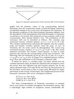
Pressure
If pressure is applied, as shown in Rg. 1, on surfaces of
the same area (Al=~=~)' the forces which are
produced are the same size (F1 F2 F3).
= =
The change in velocity may be positive (increase in
velocity/acceleration) or negative (decrease in
acceleration/deceleration).
The linear acceleration
by timet
a is given by velocity v divided
The 51 unit for acceleration (deceleration) is metre
per second squared.
Fig. 1: The hydro-static paradox
1) see footnote 1} on page 23
28
Basic Principles
2.4.2.1
Pressure due to external forces
When force F1 acts on area A 1 ,
produced of
p
a pressure is
=
Pressure p acts at every point in the system, which
includes surtace ~. The attainable force F2
(equivalent to a load to be lifted) is given by
F2
p'A2
Hence
F,
F2
A,
A,
Fig. 2: Pascal's law
The basic principle in hydro-statics is Pascal's law:
'The effect of a force acting on a stationary liquid spreads in all directions within the liquid. The amount of
pressure in the liquid is equal to the weight force, with
respect to the area being acted upon. The pressure
"'8lways acts at right angles to the limiting surtaces of the
c~nlainer.'
In addition, the pressure acts equally on all sides.
Neglecting pressure due to gravity, pressure is equal at
all points (Fig. 2).
Because of the pressures used in modern hydraulic
circuits, the pressure due to gravity may usually be
neglected.
or
F2
A,
F,
A,
The forces are in the same ratio as the areas.
Pressure p in such a system always depends on the
size of the force F and the effective area A. This
means, that the pressure keeps increasing, until it can
overcome the resistance to the liquid movement.
If it is possible, by means of force F1 and area A 1, to
reach the pressure required to overcome load F2 (via
area A2 ), the load F2 may be lifted. (Frictional losses
may be neglected.)
Example: 10m water column", 1 bar.
The displacements s1 and s2 of the pistons vary in
inverse proportion to the areas
2.4.2.2
Force Transmission
As pressure acts equally in all directions, the shape of
the container is irrelevant.
The following example (Fig. 3) will demonstrate how
the hydro-static pressure may be used.
s1
A2
S2
A1
The work done by the force piston (1) W1 is equal to
the work done by the load piston (2) W2
W1
F1 ·s1 ,
W2
= F2 • 52'
Fig. 3:' Example of force transmission
29
Basic Principles
2.4.2.3
Pressure transmission
2.4.3.1
Flow Law
If liquid flows through a pipe of varying diameters, at any
particular time the same volume flows at all points. This
means, that the velocity of liquid flow must increase at a
narrow point (Fig. 5).
Flow 0 is given by the volume of fluid V divided by
timet
o
VII.
Fig. 4: Pressure transmission
Two pistons of different sizes (Fig. 4: 1 and 2) are fixed
together by means of a rod. If area A 1 is pressurised
with pressure Pl' a force F 1 is produced at piston (1).
Force F1 is transferred via the rod 10 area ~ of piston
(2) and hence pressure ~ is obtained there.
F,=F2 and p,'A, =p"A,.
P1· A 1 = F1 and
~• ~
Liquid volume V is itself given by area A times length s
(Fig.6a)
v
Ignoring losses due to friction:
Hence
Fig. 5: Flow
= F2
or
If A· s is substituted for V (Fig. 6b), 0 is then given by
A's
o
t
Distance 5 divided by time t is velocity v
P2
A1
In pressure transfer the pressures vary in inverse
proportion to the areas.
t
Flow 0 hence equals the cross-sectional area of the
pipe A multiplied by the velocity of the liquid v
(Fig.6c)
2.4.3
Hydro-kinetics
o
=
Hydro-kinetics 1) is concerned with the liquid flow laws
and the effective forces which result. Hydro-kinetics
may also be used to partially explain the types of losses
which occur in hydro-statics.
If the frictional forces at limiting surfaces of objects and
liquids are ignored and those between the indivfdualliquid layers are also ignored, it may be assumed that the
flow is free or ideal.
The important results and conformity to the natural laws
for ideal flows may be adequately described and are
dealt with in the following sections.
FIQ.6a
Fig.6b
Fig.6c
1) see footnote1) on paQe 23
30
Fig. 6: Flow
A- v.
Basic Principles
The same flow Q in Umin occurs al any point in the
pipe. II a pipe has cross-sectional areas At and ~,
corresponding velocities must occur at the crosssections (Fig. 7)
0,
Al • v, '
°2
A,. v2
Pst+ p • g • h + -
• .,;
2
=
.
Let's now consider both the continuity equation and the
Bernoulli equation. The following may be deduced:
Hence the continuity equation is produced
0,.
p
=
Plot
whereby
Pst
= static pressure,
p. g. h = pressure due to height of head of liquid,
(pI2) • .,; back pressure.
°2'
0,
With respect to pressure energy, this means
If the velocity increases as the cross-section
decreases, movement energy increases. As the total
energy remains constant. potential energy and/or
pressure must become smaller as the cross-section
decreases.
A,
0,
There is no measurable change in potential energy.
However, the static pressure changes, dependenl
upon the back pressure, i.e. dependent on the velocity
of flow. (Fig. B: The height of Ihe head of liquid is a
measure of the pressure present at each head.)
FiQ. 7: Velocity of flow
2.4.3.2
Law of conservation of energy
The law of conservation of energy, with respect to a
flowing fluid, states that the total energy of a flow of
liquid does not change, as long as energy is not
suppli.ed from the outside or drained to the outside.
Fig. 8: Dependence of columns of liquid on pressure
Neglecting the types of energy which do not change
during flow, the total energy is made up of:
Potential energy
.,. positional energy, dependent on the height of
It is mainly the static pressure which is of importance in
"hydro-static systems·, as the height of head of liquid
and velocity of flow are usually too small.
head of liquid and on static pressure
and
2.4.3.3 Friction and pressure losses
Kinetic energy
.,. movement energy, dependent on the veloci!y
of flow and on back pressure.
Hence Bernoulli's equatton is produced
g·h
p
..
+ - +-= constant.
p
2
So far in looking at conformity to nalurallaws for liquid
flow, we have assumed that there is no friction between
liquid layers as they move against each other and also
that there is no friction as liquids move against an
object.
However, hydraulic energy cannot be transferred
through pipes without losses. Friction occurs at the pipe
surface and within the liquid, which generates heal.
Hence hydraulic energy is transformed to heat. The
loss created in this way in hydraulic energy actually
means that a pressure loss occurs within the hydraulic
circuit.
31
Basic Principles
The pressure loss - differential pressure - is indicated by
L!p (Fig. 9). The larger the friction between the liquid
layers (internal friction), the larger the viscosity
(tenacity) of the liquid becomes.
Fig. 10: Laminar flow
Fig. 9: Viscosity
Frictional losses are mainly dependent upon:
- Length of pipe,
- Cross-sectional area of pipe,
- Roughness of pipe surface,
Fig. 11: Turoufent flow
- Number of pipe bends,
- Velocity of flow and
:.... Viscosity of the liquid.
2.4.3.4.1
Reynold's number Re
The type of flow may be roughly determined using
Reynold's number
v· dh
2.4.3.4 Types of flow
=
Re
The type of flow is also an important factor when
considering energy loss within a hydraulic circuit.
whereby
'There are two different types of flow:
d
h
v
A
U
v
cross-sections equal to the pipe internal
diameter, and otherwise calculated as
d h = 4' AlU,
= cross-sectional area,
= circumference,
= kinetic viscosity in m2/s and
Recrit
.. ~
- Laminar flow and
- Turbulent flow.
Up to a certain velocity, liquids move along pipes in
layers (laminar). The inner-most liquid layer travels at
the highest speed. The outer-most liquid layer at the
pipe surface does not move (Rg. fa). If the velocity of
flow is increased, at the critical velocity the type of flow
changes and becomes whirling (turbulent, Fig. 11).
Hence the flow resistance increases and thus the
hydraulic losses increase. Therefore turbulent flow is
not usually desirable.
The critical velocity is not a fixed quantity. It is
dependent on the viscosity of a liquid and on the crosssectional area through which flow occurs. The critical
velocity may be calculated and should not be exceeded
in hydraulic circuits.
32
= velocity of flow in mis,
= hydraulic diameter in m, with circular
This value only applies for round, technically smooth,
straight pipes.
At Re
the type of flow changes from laminar to
cril
turbulent and vice versa.
Laminar flow occurs for Rs < Recrit ' and turbulent
flow occurs for Re > Recrit -
Basic Principles
3.
Hydraulic circuits
3.2.1
3.1
Important characteristics of
hydraulic circuits
Hydraulic pumps are primarily used to convert energy
and next hydraulic cylinders and motors do so.
-
Transfer of large forces (torques) at relatively small
volumes.
-
Operation may commence from rest under full load.
-
Smooth adjustment (open loop or closed loop control)
of the following is easily achieved:
• speed
• torque
• force
-
Simple protection against over-loading.
-
Suitable for both quick and very slow controlled
sequences of movements.
-
Storage of energy with gases.
-
Simple central drive system is available.
- Decenlralised transformation of hydraulic into
... mechanical energy is possible.
3.2
3.2.2
Energy conversion
Control of energy
Hydraulic energy and its associated transfer of power
exist in a hydraulic circuit in the form of pressure and flow.
In this form, their size and direction of action are effected
by variable displacement pumps and open loop
and closed loop control valves.
3.2.3
Transport of energy
The pressure fluid, which is fed through pipes, hoses and
bores within a manifold, transports the energy or only
transfers the pressure.
3.2.4
Further information
In order 10 store and take care of the pressure fluid, a
series of additional devices are necessary, such as tank,
filter, cooler, heating element and measurement and
testing devices.
Design of a hydraulic circuit
Mechanical energy is converted 10 hydraulic energy in hydraulic circuits. This energy is then transferred as
hydraulic energy, processed either in an open loop or
closed loop circuit, and then converted back to
mechanical energy.
Fig. 12: Transfer of energy in a hydraulic circuit
33
Basic Principles
3.3
Design 01 a simple hydraulic circuit
In the following sections. a simple circuit will be designed
and illustrated via sectional diagrams and symbols to
DIN ISO 1219.
3.3.1
Step 1 (Figs. 14 and 15)
Hydraulic pump (1) is driven by a motor (electric motor or
combustion engine). It sucks fluid from tank (2) and
pushes it into the lines of the hydraulic circuit through
various hydraulic devk:es up to the hydraulic cylinder (5).
As long as there is no resistance to flow, the fluid is
merely pushed further.
Cylinder (5) at the end of the line represents a resistance
to flow. Pressure therefore increases until it is in a
position to overcome this resistance, Le. until the piston
in the cylinder (5) moves. The direction of movement of
the piston in the cylinder (5) is controlled via directional
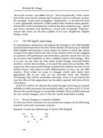
FIQ. 13: Principle of a hydraulic circuit
The piston of a hand pump is loaded with a force (Fig.
13). This force divided by the piston area results in the
att~.ab'e pressure (p
valve (6).
At rest, the hydraulic circuit is prevented from being
drained via the hydraulic pump (1) by check valve (3).
= FlA).
The more the piston is pressed on, i.e. the greater the
force on the piston is, the higher the pressure rises.
However, the pressure only rises until, with respect to the
cylinder area, it is in a position to overcome the load
(F=poA).
1f the load remains constant, pressure does not increase
any further. Consequently, it acts according to the
resistance, which is opposed to the flow of the liquid.
The load can therefore be moved, if the necessary
pressure can be built up. The speed, a1 which the load
moves, is dependent on the flow which is fed to the
cylinder. With reference to Fig. 13, this means that the
faster the piston of the hand pump is lowered, the more liquid per unit time is supplied to the cylinder, and the faster
the k>ad will lift.
In the illustrations shown in Figs. 14 to 19, this principle
(Fig. 13) is extended to further devices, which
_ control the direction of movement of the cylinder
(directional valve),
_ effect the speed of the cylinder (flow control valve),
_ limit the load of the cylinder (pressure relief valve),
_ prevent the system at rest from being completely
drained via the hydraulic pump (check valve) and
_ supply the hydraulic circuit continuously with
press,ure liquid (via an electric motor driven
hydraulic pump)
34
Fig. 14