THỰC HÀNH LẬP KẾ HOẠCH CHUYẾN ĐI (PASSAGE PLANNING PRACTICE)
Bạn đang xem bản rút gọn của tài liệu. Xem và tải ngay bản đầy đủ của tài liệu tại đây (2.38 MB, 57 trang )
First published 2006
ISBN 13: 978 1 85609 323 1
ISBN 10: 1 85609 323 9
British Library Cataloguing in Publication Data
Passage Planning: Practice
1. Navigation
623.8’9
ISBN-13: 9781856093231
ISBN-10: 1856093239
© Witherbys Publishing Ltd and Seamanship International Limited 2006
All rights reserved. No part of this publication may be reproduced, stored in a retrieval system, or
transmitted in any form or by any means, electronic, mechanical, photocopying, recording or
otherwise, without the prior permission of the publishers.
Notice of Terms of Use
While The advice given in this book (Passage Planning Practice) has been developed using
the best information currently available, it is intended purely as guidance to be used at the
user’s own risk. Neither Witherbys Publishing or Seamanship International accepts any
responsibility for the accuracy of any information or advice given in [he document or any
omission from the document or for any consequence whatsoever resulting directly or
indirectly from compliance with or adoption of guidance contained in the document even if
caused by failure to exercise reasonable care.
This publication has been prepared to deal with the subject of Passage Planning. This should
not however, be taken to mean that this publication deals comprehensively with all the issues
thai will need to be addressed or even, where a particular issue is addressed, that, this
publication sets out the only definitive view for all situations.
The opinions expressed are those of the authors only and are not necessarily to he taken as
the policies or views of any organisation with which he or they have any connection.
Jointly published and printed in 2006 by:
Witherbys Publishing Ltd.
32-36 Aylesbury Street
London EC1R OET. UK
Telephone: +44 (0)20 7251 5341
Email: bookswilherbys.com
www.witherbys.com
ii
Seamanship Inlernational Ltd
Willow House, Strathclyde Business Park
Lanarkshire ML4 3PB, UK
Telephone: +44 (0)1698 464 333
Email. info(seamanship.com
www.seamanship.com
Foreword
Acknowledgements
All ships should prepare a passage plan that
covers the voyage from the departure berth to
the arrival berth. It should adhere to national
and international regulations as well as any
Company Standing Orders. Where
appropriate, it must also follow navigational
advice and standards within the Company’s
Safety Management System.
This product has been derived in part from
material obtained from the UK Hydrographic
Office with the permission of the UK
Hydrographic Office, Her Majesty’s
Stationery Office.
Ships of a particular company are likely to
adopt a similar format for their passage plans,
although variations caused by cargo type,
vessel type or draught or commercial
agreements are possible.
THIS PRODUCT IS NOT TO BE USED
FOR NAVIGATION.
The passage plan described here has not been
prepared to any specific company instructions.
Notices
The UK Hydrographic Office (UKHO) and its
licensors make no warranties or
representations, express or implied, with
respect to this product. The UKHO and its
licensors have not verified the information
within this product or quality assured it.
The main difference between passage plans is
in the layout. In general, company specific
documents, such as pro-formas and checklists, are used. For this plan, we have provided
a generic layout, which balances the
information on the chart with other related
passage plan documents. Remember to use all
relevant passage plan documents in
conjunction with the navigational charts.
This book is designed to be read alongside the
first chapter of Passage Planning Principles
(ISBN 1 85609 320 0), where many of the
terms and concepts are described in more
detail.
iii
Preface
The two books ‘Passage Planning Principles’
and Passage Planning Practice’, both by
Abdul Khalique and Capt. Nadeem Anwar,
together provide a comprehensive, easy to
follow guide and an excellent set of standards
to be worked through.
By providing check-lists and a fully worked
example, the authors have created a guide
that builds upon the sound principles of
passage planning, that can be used in a real
life situation, providing a much needed ‘job
based’ training aid.
At Northern Marine Management we
recognise the importance of good passage
planning to support the bridge team and
ensure that the ship can be safely navigated
between ports from berth-to-berth. We
welcome such books into the industry as a
valuable training aid in ensuring that risks are
considered and adequate measures put in
place to ensure a safe passage.
iv
I would encourage all Bridge Officers,
experienced or otherwise to consider
checking their own passage planning
standards against these two works,
particularly with reference to the highly
important section on Risk Assessment.
The Witherbys/Seamanship range of books
are written in a straightforward and readable
style that makes them a must for all nautical
libraries. This latest is a worthwhile addition
to that range.
Terry Luke
Chairman, Informal Tanker Operators Safety
Forum
May 2006
Contents
Foreword
iii
Preface
iv
About the Authors
vii
Passage Planning
1
1. Voyage Instructions
3
2. Confirmation of Dention
3
3
3
3
2.1 Task 1: Confirm Destination
2.2 Task 2: Establish Route
2.3 Task 3: Calculate Distances
3. Appraisal
3.1 Task 4: Collate Company, Master and Charterer’s Instructions
3.2 Task 5: Gather General Information
3.3 Task 6: CoIled and Note Cargo Information
4
4
4
4
4. Planning
5
4.1 Procedure for Chart Selection
5
4.2 Task 7: If the largest-scale charts,.they must be requisitioned
7
4.3 Task 8: Identify predicted areas of danger and mark on charts
7
4.4 Task 9: Lay-off the courses, clear of hazards and dangers
9
4.5 Calculation of Wheel Over Point
10
4.6 Steps to Draw Wheel-Over Bearing by Advance Transfer Method
10
4.7 Use of Large Scale Plans within Small Scale Charts
12
4.8 Task 10: Mark all identified hazards
14
14
4.9 Use of the Admiralty List of Lights’
14
4.10 Use of Admiralty List of Radio Signals
4.10.1 Navigational Warnings
14
4.10.2 Weather Reports/Fax
15
4.11 Calculation ol Radar Horizon
15
4.12 Transferring Position from one Chart to another Chart
16
4.12.1 Range and Bearing Method
16
4.12.2 DMP Method
16
4.13 Use of Admiralty List of Radio Signals for Information about RACONS
17
4.14 Use of Admiralty List of Radio Signals for information on DGPS Beacons 17
4.15 Task 11: Identify the hazards 18
5. Execution
5.1 Task 12: Allocate Resources for Bridge Team Management
18
18
v
6. Monitoring
6.1 Task 13: Continuously monitor progress along the planned track
6.2 Anchor Plan
6.3 Berthing Plan
Appendices
Appendix 1: Own Passage Check-list
Appendix 2: Passage Plan, Bab-el-Mandeb to Jeddah Pilot Station
Appendix 3: Passage Plan, Jeddah Pilot Station to Berth
Appendix 4: Passage Planning Notebook
Appendix 5: Port Entry Information — Jeddah
Appendix 6: Ship’s Particulars and Manoeuvring Characteristics
Appendix 7: Chartwork Legends
vi
20
20
22
25
27
29
35
37
38
45
47
48
About the Authors
Captain Nadeem Anwar
graduated from the Pakistan Marine Academy
in December 1983 and in 1984, went into
shipping as a deck cadet on multipurpose ships.
In 1990, he started working on oil tankers and
OBOs. In 1994, he returned to Fleetwood and
acquired a Chief Mates Certificate of
Competency. He was promoted to Chief Officer
in 1994 and continued to serve on VLCC, OBO,
0/0, Gas and Chemical Tankers. He achieved
his Master Certificate of Competency from
MCA UK in early 1998 and went back to sea in
command of VLCCs. His time at sea was
mainly spent in deep-sea trade, which gave him
a wide ranging experience of
navigating in different areas of the world.
In October 1998, he joined the Fleetwood
Nautical Campus as a lecturer. In 2003, he
became its Curriculum Manager. In 2005, he
achieved an MSc in Maritime Operations with a
Distinction (through LJMU) and an Advanced
diploma in Insurance (through the Chartered
Insurance Institute).
Captain Anwar has developed training courses
and written a range of training materials. He
also provides consultancy services to marine
training providers and shipping companies.
Abdul Khalique
MCS, PG Cert. (Shipping), MSc. (CBIS),
HND Nautical Science, BSc. (Maritime
Studies)
Awarded the President of Pakistan Gold Medal
for best cadet during B.Sc. Maritime Studies at
Pakistan Marine Academy, received the High
Achievement Award and the Merchant Navy
Association (Tasmania) prize on completion of
2nd mate from the Australian Maritime College.
After obtaining an HND in Nautical Science
from the Blackpool and Fylde College in 2000,
he earned an M.Sc. in Computer Based
Information Systems from the University of
Sunderland. After this, he sailed for a while but
the incidents of 9/11/2001 made him pursue a
shore based career. He moved to New Zealand
and studied for the Graduate Certificate in
Shipping at the New Zealand Maritime School.
In June 2003 Abdul moved to SSNS at the
NAFC Marine Centre as an HND Nautical
Science course developer He continued in this
position until the Centre started training cadets,
when he became a lecturer in Nautical studies.
While in this position, he passed the Institute of
Chartered Ship Brokers examination and has
recently been elected as a member of the
Institute.
vii
Passage Planning
2
1 Voyage Instructions
For the example demonstrated in this book, the
vessel is sailing from Aden and heading towards
the Suez Canal, with charter party instructions
‘M.V. One Voyager on voyage 032-2005 WB’. It
is on a westbound pendulum service, from
Japan/Far East to the US East coast, between the
ports of Tokyo, Yokohama, Nagoya, Hong Kong.
Singapore, Penang, Jeddah, Genoa, Barcelona,
Philadelphia and New York.
Jeddah Call
(Container Terminal Berth No. 52/53)
Max draft: Not to exceed 15.0 m
Tugs available: Minimum 2
Side alongside: Any
Shore gantries: Minimum 4
Tidal restrictions:None
Weather restrictions: None
Stay: 6 to 12 hours
Date: 23rd March 2005 (Yemen Local Time 1800
Hrs-Standard Time +0300 UTC)
The Master passes these instructions to the
Navigation Officer and asks to amend the passage
plan so that the vessel will proceed to the Jeddah
Pilot Station and then on to berth No. 52/53.
2 Confirmation of
Destination
2.1 Task 1: Confirm
Destination
The Navigation Officer confirms the
latitude/longitude of the destination port, the
anchorage berth and the wharf number from
the Master. The Navigation Officer should
prepare the passage plan from scratch,
including the passage plan through the Strait of
Bab-el-Mandeb.
2.2 Task 2: Establish
Route
The Navigation Officer confirms the
destination port (by latitude/longitude or
country) and begins at Stage 1 of the passage
plan.
The Navigation Officer will now establish the
route by reference to ‘Sailing Directions’.
Note that in ‘Ocean Passages for the World,’
routes for the Red Sea are not included as they
are seen as coastal routes (Para 6.51 Page 66
NP 136). Therefore, use ‘Sailing Directions’ as
the reference.
2.3 Task 3; Calculate
Distances
From the British Admiralty Chart No. 4704
(small scale) and British Admiralty Chart Nos.
157 and 158, the Navigation Officer estimates
the distances on the route identified. In
addition, the routes are roughly drawn
according to the recommendations in the
‘Sailing Directions’.
Use BA Chart 157 to provide the Master with
detailed information and references from
publications (such as ‘Sailing Directions’) to
justify the offered choices.
The two available routes through the Red Sea
are:
• East of Abu-Ali-Island
• West of Hanish-Al-Kubra
These two options are similar as the western
route is only four miles Longer than the
eastern. But, because of hazards on the western
route, as described in the provided information,
the Master selects the eastern route. Discuss
and agree this route with the Master before
calculating distances.
3
The distances are:
• From Strait of Bab-el-Mandeb to the
Jeddah Pilot: 606.5 nautical miles
• From the Jeddah Pilot to the Container
Terminal (Berth No. 52 or 53):
4 nautical miles.
Based on the distance, calculate the Expected
Time of Arrival (ETA) and notify the Master.
Also inform the Chief Engineer about the sea
passage and the steaming time to the harbour.
ETAs:
Total Distance
606.5 miles
Steaming Time © 25.0 knots
24 h l5 m or
01d 00 h l5 m
Time (UTC) at present position
March
23 rd 15 h 00 m
ETA (UTC) at Jeddah Pilot Station
March
24 th l5 h 15 m
Zone Time Saudi Arabia (-0300)
UTC
+
03 h 00 m
Manoeuvring Time to arrive at Pilot Station
02 h 00 m
ETA (Local Time) for Pilot, Agent, etc.
March
24 th 20 h 15 m
Manoeuvring at Anchorage
(Both Arrival/Departure)
01 h 00 m
Manoeuvring from Anchorage
to Berth
01 h 00 m
3 Appraisal
3.1 Task 4: Collate
Company, Master and
Charterer’s
Instructions
The Navigation Officer collects the
instructions from the company, the charterer
and the Master with respect to the intended
passage and notes them for the required route.
4
3.2 Task 5: Gather General
Information
from Publications,
Notices, Radio bulletins,
Colleagues and Old
Passage Plans
This includes information from radio bulletins,
colleagues, previous Passage Plans, previous
Ship Visit reports and publications such as
Guide to Port Entry.
3.3 Task 6: Collect and
Note Cargo
Information, Draught
of Vessel and
Manoeuvring Data
Once the basic data has been collected,
obtain information about the cargo and the ship
and keep it for reference. The
Navigation Officer will ask the Chief Officer
for arrival/departure draughts, air draughts and
any special requirements with respect
to the cargo. This information is also
relevant:
Draught = 14m
Cargo = Containers (No reefer/ Dangerous
Cargo)
Manoeuvring Data - Given in Appendix 6
Once the Navigation Officer has the basic
information about the vessel and the passage
for the intended voyage, he can consider
‘section b — publications. d— Weather f —
assage’ of the check-list (see Appendix 1).
Once the publications listed in the checklist
have been consulted, the Master and
Navigation Officer will make an overall
assessment of the intended course.
4 Planning
4.1 Procedure for Chart
Slection
The navigation charts are the most
Important part of a ship’s navigational
resources. The Navigation Officer selects Ihe
most appropriate charts from the Catalogue of
Use the Admiralty Chart Catalogue Part 2 —
Limits of Admiralty Chart Indexes’, to
identify the section of the chart catalogue and
the page number from which chart numbers
will be identified and selected. In this case,
Page H2 of the Admiralty Chart Catalogue
(inset of Figure 1) is the correct selection. Note
this in the Passage Planning note book.
Admiralty Charts and other Hydrographic
Publications (NP 131)’usually referred to as
the Admiralty Chart
Catalogue’,
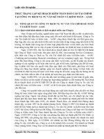
Figure 1 — Copy from Catalogue of Admiralty Charts (NP 131) Part H2 — Red Sea
5
Figure 2 — Copy from Catalogue of Admiralty Charts (NP 131) Part 2— H2 — Red Sea
(Southern Part Inset)
In addition, use The World General Charts
of Oceans’ to select the small scale charts for
the overall area and use ‘The World Index of
Charts’ to select the slightly larger scale
charts (1: 3,500,000). In this case, Chart 4071
and 4704 would be the correct choice.
The required charts are shown In Figure 1.
For accuracy, the Navigation Officer uses a
2B pencil to draw an approximate route line
on page H2 of the ‘Admiralty Chart
Catalogue’. The selected charts are:
6, 157, 158, 2577, 2599. 2658, 2659
6
Figure 2 is the inset B’ referred to in Figure 1.
Draw an approximate route on the inset, using
the following charts:
143, 453, 1925, 2588, 3661
Once all the required charts have been
selected, the Navigation Officer can now use
the Chart Correction Log and Folio Index
(NP133A) to check their edition numbers of
the on board copies and add any required
corrections.
4.2 Task 7: If the largestscale charts for the
voyage (or part of the
voyage) are not
onboard, they must be
requisitioned
• Value of squat, from ship’s
manoeuvring data
Not available
• Speed2 (in knots) ÷100 in
metres
• 10% of the draught
• 0.3 metres for every 5 knots
of ships forward speed
6.25 m
1.40 m
1.50 m
For a maximum speed of 25 knots, use a squat
value of 6,25 m as ‘worst-case. Squat has its
maximum effect in depths of 21 m or less
Use the British Admiralty’s website at the URL (draught of 14 m x 1.5 = 21 m). Make dditional
allowances for prevailing weather and other
to Find the
factors. In this case, a UKC of 7m has been
charts required for an area. On this website,
used for legs where the ship would be at full
users can search for the required charts by:
speed, that is, safe in a depth of water of 21m.
• Chart number
From the courses on smaller scale charts and
• world map
with extra information from publications such
as ‘Sailing Directions’,’ IMO Routeing Guide’,
• chart type
and ‘Ocean Passages for the World’, the
• chart title
Navigation Officer can identify navigational
hazards, no-go areas, conspicuous shore objects
• Admiralty Folio.
and other factors that may affect the passage.
Note these limitations to the web-search
Mark items like these on the charts:
method:
• Conspicuous Points: used for visual or radar
• Does the ship have a high-speed internet
position fixing (see Figure 3 —
connection?
Conspicuous Peak 69 m)
• That charts are given for the entire area.
• Cross Index Ranges (CIR) for parallel
- For example, the Admiralty Folio 32 indexing (see Figures 3 and 4)
RED SEA andARABIAN SEA’gives 60
charts for all the ports in the area, whereas
• margins of safety, that is, the maximum
the actual number of charts required may be
cross track error allowed (see Figures 3, 5
considerably fewer.
and 6)
If the required editions of any charts are not on
board, they must be requisitioned urgently.
4.3 Task 8: Identify redicted •
areas of danger and mark
on charts
•
To define the dangers, establish the Underkeel
Clearance (UKC) for various stages of the
passage. Remember squat. To provide a margin
of safety, the value used should be the greater
of:
Way Point Number (WPT) with Distance to
Go (DTG). DO NOT write Latitude and
Longitude (see Figure 3 — WPT 2)
Highlight ‘Notes’ for the attention of the
Watchkeeping Officers
• Calculate tidal streams, enter them on the
chart. Highlight tidal diamonds (if they
apply) and draw an arrow in the ‘set’
direction (see Figure 3 - tidal diamond A)
7
Figure 3— Copy from BA Chart 452 — Steps to draw Wheel-Over Bearing
• mark predicted areas of danger or ‘no
go’ areas (see Figure 6 - area around
“Farasan Bank”)
• mark areas where depth is critical and the
8
echo sounder is required (see Figure 6)
The Navigation Officer uses the bridge
Complete these tasks:
notebook to record items marked on the charts,
reference(s) to publications and other important
items. Information is noted under these
headings:
• Adopt a pattern for marking on charts. For
• Coastal Features for Position Fixing, for
example: conspicuous objects, lights,
RACONS and the nature of the coastline
• Directions, for passage through the
identified leg of the passage
• hazards, as identified from ‘Admiralty
Sailing Directions’
a weather, information obtained from
Admiralty Safling Directions
• Tides/tidal streams/currents, as
calculated or obtained from Tide Tables,
Tidal Stream Atlases
• Additional Information, for example:
piracy/armed robbery, with reference to
Admiralty Sailing Directions or to the
Admiralty List of Radio Signals (ALRS)
• IMO Routeing Guide. If there is a Traffic
Separation Scheme (TSS) in the area, use
this publication to obtain information and
include it in the bridge notebook.
4.4 Task 9: Lay-off the
courses, clear of
hazards and dangers
The Navigation Officer must lay the charts in
sequence and mark the sequence number on the
back of the charts so that they stay in the correct
order. Place the sequence number on the back
of the chart between the ‘(Folio No….
Consecutive No…. and the Chart title. Use a 2B
pencil so that it can be erased when the voyage
is over.
The Navigation Officer will by now have
selected the route, marked the predicted areas of
dangers and calculated the tidal streams. The
next step is to lay-off the courses clear of all the
dangers.
examples of the legends to be used for
Chartwork, refer to Appendix 7
• lay-off courses that are clear of dangers, as
recommended by Sailing Directions.
Complete the Passage Planning Note Book’
and fill in the ‘Plan Sheet’. Remember that
courses are laid down from berth-to-berth
• Once the courses are laid down, mark:
- Course (always true with ‘T’ on chart) and
distance with each leg
- waypoint number(s) (WPT) along with
DTG to destination - for example, pilot
station. Use this to refer to the passage
plan sheet, GPS and ECDIS (if used)
- Wheel over points
- Wheel over points, ranges and bearings of
landmarks used
- CIR for parallel indexing
- Clearing bearings/lines, to clear a specific
hazard, particularly when making
approaches in narrow channels
- Cross track errors/margins ot safety.
- Pilot boarding/disembarkation position(s)
- Speed reduction points
- Abort points / points of no return
- The sequence of charts for the passage
- the set and rate of current, height of tide
- the next chart and its number
- transit bearings, [or quick check of
compass error
- the position on the chart where it will be
necessary to switch on certain navigations
aids, such as the echo sounder
- navigational warnings and preliminary and
temporary chart corrections, as taken from
notices to mariners
- specific meteorological information
available, for example, dust storms,
restricted visibility, sea, swell and wind
conditions
- areas where specilic marine environmental
protection
considerations apply
9
- chart datum is usually given on the chart.
set squares.)
The standard used by GPS systems is
5. On the perpendicular line, draw a line
WGS 84. But if any chart has a different
(shown in green in diagram) parallel to
datum, highlight this to make the OOWs
present course (300) at a distance equal to
aware of it
transfer (1.3 cables) from the present course
- minimum UKC required, particularly in
(300).
shallow water areas
6. The point where this parallel line (green)
- references to contingency plans for
intersects the new course (334’) is point
alternative actions to maintain the safety of
C.
life, environment, vessel and the cargo
4.5 Calculation of Wheel Over Point
10° Rudder - Speed Full Ahead — draft 14m
Fully Loaded
Course
Speed
Alteration after Turn
(Deg)
(Knots)
34C
25.4
Advance
Transfer
(Cables)
6.7
1.3
4.6 Steps to Draw WheelOver Bearing by
Advance-Transfer
Method:
1. From the manoeuvring data of the ship.
obtain advance and transfer as shown in the
table at 4.5. (Note. the method for
calculation of WO is shown in the inset
of the diagram).
2. Using Figure 3, extend the present course
line (300T) beyond the alter course
waypoint (WPT2).
7. Draw a line from point C to the extension of
the present course line (300). The point
where this line intersects the extension of
the present course is D. The distance CD is
equal to transfer and lineCD is perpendicular
to present course (300).
8. From point D beyond point , on the present
course line (300’), draw a line equal to
advance (6.7 cables) as shown in diagram
(blue). This point is called W and is the
wheel over point for alteration of course to
334.
9. Determine bearing of the light house (Balfe
Point Light) and write on chart to use for
corn mencement of course alteration.
Note: This WO point (W) is only valid if the
vessel does not have cross track error. The
vessel will follow curved path WC (in red) as
shown in diagram.
Use this formula to determine the distance
backwards from the waypoint for marking the
wheel-over point:
Distance backwards from WPT = Advance (transfer ÷ tan of course alteration0)
In the example above, for a course alteration of
34° with advance and transfer of 6.7 and 1 .3
respectively:
3. Mark the intersection of the new course
(334’) and present course (300’) as point ‘B’ Distance backwards from WPT 2 = 6.7 - (1.3 ÷
tan 34°) 4.8 cables
4. From any point on present course (300’),
draw a perpendicular, that is, at 90 to the
present course line. (Use parallel rulers or
10
Figure 4 — BA Chart 453 — Example of Tidal Stream Calculation and Marking on Chart
11
Figure 5— Copy from BA Chart 453 — Use of Plan
While laying down the course, as directed by
the circumstances and the information given
in the Admiralty or other publications, the
Navigation Officer can add notes in the bridge
note book under the column ‘General Notes
(Own Notes for Navigation of Vessel)’ for
execution and monitoring of the passage plan.
This makes sure that the Watchkeeping
Officers have clear and precise instructions on
how to conduct the passage.
12
4.7 Use of Large Scale Plans
within Small Scale Charts
Charts like those in Figure 6 show a large
area of sea, but they often have a larger
scale plan inset to show details of the
coastal features. Make a note on the chart
at the points where you intend to use the
inset (see Figure 5 and 6).
Figure 6 – Copy from BA chart 143
13
6140 Jebel at Tair 15 32.8 F1 W 5s 162 17 White round metal ft 0.2 vis 3110 – 2020 (2510)
41 49.8
and lantern
20
Figure 7a – ALL Vol. E – Page No. 305
4.8 Task 10: Mark all
Identified Hazards and
any Additional
Information on Chart
without any
information overload
For accurate bridge team management, and
for timely advice from port control and the
pilot station, keep the passage information
organised and readily available. Highlight
these items:
•
•
•
•
Reporting points. If there are stations
to be called or report ETAs to be sent,
note the location, IDs and VHF
channels in the passage plan sheet/note
book and on the chart
the position where the engine room is
given one hour’s notice to place the
engines on stand-by for manoeuvring
on the course line, show where notices
should be given to additional
watchkeepers, helmsmen and lookouts
on the chart, indicate where piracy
watches must be kept, the pilot ladder
is to be rigged and anchors and
mooring lines kept ready.
4.9 Use of the ‘Admiralty
List of Lights’
While planning the passage, the Navigation
Officer must check the current status of the
lights/light houses and provide additional
information for use during the monitoring
stage. If the lights are to be used, identify
14
them correctly. During daylight when the light
is not visible (or when a light is
malfunctioning), Watchkeeping Officers must
use the details of the lighthouse structure,
height, colour and material to Identify it.
See Figure 7a for an example for the Jebel at
Tair light. From the Admiralty List of Lights
(ALL), the Navigation Officer selects the light
number and writes it on the chart (as shown in
Figure 5). Use this ni.Jmber to find the
lighthouse details in the relevant publication.
Information obtained from ALL is shown in
Figure 7a.
This information can be used with the
Luminous Range Diagram (see Page iii of
ALL Vol. E), to find the approximate range at
which a light may be sighted in the prevailing
visibility. As an example (see the graph at
Figure 7b), the nominal range of light at Jebel
at Tair (given in the ALL description and/or
on navigational chart) is 17 n. miles. lithe
visibility is 5 n. miles, then the range at which
this light will be visible is 10.5 n. miles.
4.10 Use of ‘Admiralty List of
Radio Signals’
These are for information on:
4.10.1 Navigational Warnings
Volume 5:
NAVTEX Station covering the region is
[H]—Jeddah
Jeddab [H ] is also used for the onward
passage.
Figure 7b — ALL Vol. E — Page No. iii — Use of Luminous Range Diagram
4.10.2 Wheather Reports/Fax
Volume 3 (Part 1):
Page: 46, 47, 49
Station: Northwood
4.11 Calculation of Radar
Horizon
Use this (ormula to find the range at which
an object can be detected on radar.
R=2.23 ( h + H )
where:
R = Radar Horizon in nautical miles
h = height of radar antenna in metres
H = height of target in meters
R = 2.23 ( 44.3 + 87 )
= 35,6 miles
If the radar is working at its f5eak power and
has no range limitations, it should be able to
pick up Pile Island at a range of 35.6 miles.
But if the radar performance has been
impaired or the atmospheric conditions are
nonstandard, an echo may not appear at this
range because the radar horizon may have
been reduced or increased through subrefraction or super-refraction.
Check the radar log to see the range at which
an island or land appeared on radar during
the previous voyage. This is particularly
important for landfall planning.
For this example, the object chosen is Pile
Island (see Figure 4), charted height 87m,
height of antenna 44.3m (height from keel to
radar scanner less draught of ship, see
Appendix 6). Using these values in the above
formula:
15
4.12 Transferring Position
From One Chart to
Another Chart
When transferring positions from one chart to
another, it is possible for the new position to
appear in a slightly different location
(reference to the course line) than shown in
the previous chart.
Note: wherever possible, transfer positions as
a range and bearing from a prominent
headland rather than from a latitude/longitude
position.
Two simple methods for plotting the course
accurately on different charts are provided
below:
4.12.1 Range and Bearing
Method
Transferring position by range and bearing is
a well-tested method where the
Navigation Officer can use these steps:
• Instead of measuring latitude and
longitude from one chart and carrying
them onto the next, plot the position on
one chart and then measure the range and
bearing of the plotted position from a lixed
object
• on the next chart, plot the range and
bearing from the same fixed object to
obtain the position without discrepancy.
The above method is shown in Figure 8,
transferring a position from chart 157 to chart
158. on chart 157, the position is plotted by
latitude and longitude 1W 52.O’N, 039 51
.0E, but when the same position is plotted on
chart 158 with latitude and longitude and
compared with the range and bearing of
Mubarak Reef (a fixed object), the two
positions vary. When navigating a ship, the
main objective is to keep a safe distance away
from shore objects, the range and bearing
method is preferred.
4.12.2 DMP Method
The second method for transferring position
lines is based upon Meridional Parts. An
example is shown for the course between
WPT 7 and WPT 8 below:
Step 1: accurately calculate the course
between the two positions:
WPT 7 :
Latitude 180 52.0’N
MP
1145.4646
Longitude 0390 51.0”E
WPT 8
Latitude 210 15.0’N
MP
296.7979
Longitude 0380 50.0’E
D’Lat 143’N
DMP 151.3333 D’Long 61 ‘W
D' Long
Tan Course =
DMP
Figure 8 — BA Chart 158 — Transferring Position to Next Cha
16