SERVICE MANUAL toshiba e550 e650 e810
Bạn đang xem bản rút gọn của tài liệu. Xem và tải ngay bản đầy đủ của tài liệu tại đây (13.31 MB, 346 trang )
SERVICE MANUAL
DIGITAL PLAIN PAPER COPIER
e-STUDIO550/650/810
(DP-5510/6510/8110)
File No.31100202
2002-06
Copyright 2002
TOSHIBA TEC CORPORATION
GENERAL PRECAUTIONS REGARDING THE INSTALLATION
AND SERVICE FOR THE COPIER e-STUDIO550/650/810
The installation and service should be done by a qualified service technician.
1.
Transportation/Installation
• When transporting/installing the copier, move it by the casters while lifting the stoppers.
The copier is quite heavy and weighs approximately 200 kg (441 lb), therefore pay full attention
when handling it.
• Be sure to use a dedicated outlet with AC 115V or 120V/20A (220V, 230V, 240V/10A) or more
for its power source.
• The copier must be grounded for safety.
Never ground it to a gas pipe or a water pipe.
• Select a suitable place for installation.
Avoid excessive heat, high humidity, dust, vibration and direct sunlight.
• Also provide proper ventilation as the copier emits a slight amount of ozone.
• To insure adequate working space for the copying operation, keep a minimum clearance of
80 cm (32”) on the left, 80 cm (32”) on the right and 10 cm (4”) in the rear.
• The socket-outlet shall be installed near the copier and shall be easily accessible.
2.
Service of Machines
• Basically, be sure to turn the main switch off and unplug the power cord during service.
• Be sure not to touch high-temperature sections such as the exposure lamp, the fuser unit, the
damp heater and their periphery.
• Be sure not to touch high-voltage sections such as the chargers, high-voltage transformer,
exposure lamp control inverter, inverter for the LCD backlight and power supply unit. Especially,
the board of these components should not be touched since the electirc charge may remain in
the condensers, etc. on them even after the power is turned OFF.
• Be sure not to touch rotating/operating sections such as gears, belts, pulleys, fan, etc.
• Be careful when removing the covers since there might be the parts with very sharp edges
underneath.
• When servicing the machines with the main switch turned on, be sure not to touch live sections
and rotating/operating sections. Avoid exposure to laser radiation.
• Use suitable measuring instruments and tools.
• Avoid exposure to laser radiation during servicing.
- Avoid direct exposure to the beam.
- Do not insert tools, parts, etc. that are reflective into the path of the laser beam.
- Remove all watches, rings, bracelets, etc. that are reflective.
3.
Main Service Parts for Safety
• The breaker, door switch, fuse, thermostat, thermofuse, thermistor, etc. are particularly important
for safety. Be sure to handle/install them properly. If these parts are shorted circuit and/or
made their functions out, they may burn down, for instance, and may result in fatal accidents.
Do not allow a short circuit to occur. Do not use the parts not recommended by Toshiba TEC
Corporation.
4.
Cautionary Labels
• During servicing, be sure to check the rating plate and the cautionary labels such as “Unplug
the power cord during service”, “Hot area”, “Laser warning label” etc. to see if there is any dirt
on their surface and whether they are properly stuck to the copier.
5.
Disposition of Consumable Parts, Packing Materials, Used batteries and RAM-ICs
• Regarding the recovery and disposal of the copier, supplies, consumable parts, packing materials,
used batteries and RAM-ICs including litium batteries, it is recommended to follow the relevant
local regulations or rules.
6.
When parts are disassembled, reassembly is basically the reverse of disassembly unless
otherwise noted in this manual or other related documents. Be careful not to reassemble
small parts such as screws, washers, pins, E-rings, star washers in the wrong places.
7.
Basically, the machine should not be operated with any parts removed or disassembled.
8.
Precautions Against Static Electricity
• The PC board must be stored in an anti-electrostatic bag and handled carefully using a wristband, because the ICs on it may become damaged due to static electricity.
Caution: Before using the wristband, pull out the power cord plug of the copier and
make sure that there are no uninsulated charged objects in the vicinity.
Caution :
Dispose of used batteries and RAM-ICs including lithium batteries according to this manual.
Attention :
Se débarrasser de batteries et RAM-ICs usés y compris les batteries
en lithium selon ce manuel.
Vorsicht :
Entsorgung des gebrauchten Batterien und RAM-ICs (inklusive
der Lithium-Batterie) nach diesem Handbuch.
1.
SPECIFICATIONS / ACCESSORIES /
OPTIONS / SUPPLIES
1. 1. Specifications
1. 2. Accessories
1. 3. Options
1. 4. Supplies
1. 5. System List
1. SPECIFICATIONS / ACCESSORIES / OPTIONS / SUPPLIES
1. 1. Specifications
When the specification is different among e-STUDIO550, 650 and 810, the value for e-STUDIO650 is
shown by [ ] and the value for e-STUDIO810 is shown by { }.
• Copy process ............... Indirect electrophotographic process (dry system)
• Type .............................. Console type
• Original table ................ Fixed type (left rear corner used as a guide to place originals)
• Acceptable originals ..... Sheets, books and 3-dimensional objects
The automatic document feeder only accepts paper (single-sided originals:
50~127g/m2/13~34Ib.Bond, double-sided originals: 50~104g/m2/13~28Ib.Bond)
excluding carbon paper, pasted sheet and stapled sheet.
Maximum size : A3/LD
• Copy speed
e-STUDIO550
(Copies/min.)
Tandem
LCF
Top side discharging
55
55
48
33
Back side discharging
55
55
48
30
Top side discharging
44
—
42
33
42
—
42
30
Top side discharging
39
—
37
33
Back side discharging
35
—
35
30
Top side discharging
34
—
33
33
Back side discharging
30
—
30
30
Paper size
A4, LT, B5
A4-R, B5-R,
A5-R, LT-R, ST-R Back side discharging
B4, LG
A3, LD
Bypass feeding
Size specified
Size not specified
Cassette
Paper supply
e-STUDIO650
(Copies/min.)
Paper supply
Paper size
A4, LT, B5
A4-R, B5-R,
A3, LD
Tandem
LCF
Bypass feeding
Size specified
Size not specified
Top side discharging
65
65
48
33
Back side discharging
65
65
48
33
Top side discharging
50
—
42
33
48
—
42
33
Top side discharging
43
—
37
33
Back side discharging
40
—
37
33
Top side discharging
37
—
33
33
Back side discharging
34
—
33
33
A5-R, LT-R, ST-R Back side discharging
B4, LG
Cassette
JUNE 2002 © TOSHIBA TEC
1-1
e-STUDIO550/650/810 SPECIFICATIONS
e-STUDIO810
(Copies/min.)
A4, LT, B5
A4-R, B5-R,
Tandem
LCF
Top side discharging
81
81
50
34
Back side discharging
81
81
50
34
Top side discharging
61
—
44
34
56
—
44
34
Top side discharging
52
—
39
34
Back side discharging
45
—
39
34
Top side discharging
43
—
34
34
Back side discharging
37
—
34
34
A5-R, LT-R, ST-R Back side discharging
B4, LG
A3, LD
*
*
Bypass feeding
Size specified
Size not specified
Cassette
Paper supply
Paper size
“–” means “Not acceptable”.
Each copy speed described in the table of the previous page is available when doing a multiple copying
of the manually placed single-sided originals, and in this mode, only the top side discharging is carried
out.
*
When using the automatic document feeder, each copy speed of 55 [65] {81} copies/min. is available
only when the following conditions are met:
• Original/Mode
: Single-sided original, A4/LT size, 1 sheet/APS and automatic
density are not selected.
• Preset number of sheets: 55 [65] {81} or more.
• Reproduction ratio
*
: 100%
System copy speed
sec.
Copy mode
e-STUDIO e-STUDIO e-STUDIO
*
System copy speed, including
scanning time, is available when 10
550
650
810
sheets of A4-sized original are set
Single-sided originals
1 set
18"86
16"81
15"96
on RADF and one of the copy modes
Ꭹ
3 sets
40"17
35"99
30"52
in the left table is selected.
Single-sided copies
5 sets
61"92
53"56
45"19
Single-sided originals
1 set
21"28
20"70
20"46
Ꭹ
3 sets
42"91
39"47
36"37
Double-sided copies
5 sets
64"89
57"70
49"48
Double-sided originals
1 set
35"32
35"21
34"36
Ꭹ
3 sets
78"61
71"70
63"89
Double-sided copies
5 sets
121"96 108"01 95"06
Double-sided originals
1 set
31"77
31"49
30"88
Ꭹ
3 sets
74"75
67"97
60"58
Single-sided copies
5 sets
117"88 104"64 90"02
e-STUDIO550/650/810 SPECIFICATIONS
1-2
*
1st cassette is selected and copying
is at the sort mode.
*
Finisher, hole-punch unit and inserter
are installed.
*
Measurement deviation is included
since the system copy speed was
measured by actual measurement.
JUNE 2002 © TOSHIBA TEC
• Copy paper
Cassette
Size
Duplex copy
A3~A5R,
LCF
Bypass copy
Remarks
A4, LT
A3~A5-R, LD~ST-R,
No guarantee for 8K,
LD~ST-R, 13"LG, 8.5"x8.5",
8.5"x8.5", 8K, 16K, 16K-R 16K, 16K-R at duplex
8K, 16K, 16K-R
(Non-standard or user-
copy
specified sizes can be set.)
Weight
2
64~209g/m2
64~209g/m , 17~110lb. -index
17Ib~110Ib -index
Special
Tab paper
paper
(2nd casette only)
_
Tracing paper, labels,
Special types of paper
OHP film (thickness:
should be recommanded
80µm or thicker), tab paper
by Toshiba.
• First copy time .................. 3.3 seconds or less (A4/LT, LCF, 100%, original placed manually)
• Warming-up time ................ Approx.160 seconds (e-STUDIO550/650/810, Temperature: 20°C)
Notes: 1. This is at the condition not entering the toner supply operation.
2. The auto job start is not operated.
• Multiple copying ................. Up to 9999 copies; set number entered with digital keys
• Reproduction ratio .............. Actual ratio:
Zooming:
100±0.5%
25~400% in increments of 1%
(25~200% when using the RADF)
• Resolution/Gradation ......... Read:
......... Write:
600 dpi
Equivalent to 2400 dpi x 600 dpi
(primary scanning only : 4 division smoothing)
• Eliminated image width ...... Leading edge: 3.0±1.0 mm, Trailig edge: 2.0±1.0 mm, Side edges: 2.0±2.0 mm
• Paper feeding ..................... Automatic feeding:
Copier cassettes–2 cassettes (Paper stack height
55 mm, equivalent to 550 sheets; 64 to 80 g/m2 (17
to 22 lb.Bond))
LCF (Paper stack height 137 mm: equivalent to 2500
sheets; 64 to 80 g/m2, 17 to 22 lb.Bond)
Bypass feeding:
(Paper stack height 11 mm : equivalent to 100 sheets;
64 to 80 g/m2, 17 to 22 lb.Bond)
• Capacity of originals in the automatic document feeder
................. A3~A5-R, LD~ST-R
: 100 sheets
• Automatic duplexer ............ Stackless, Switchback type
• Toner supplying .................. Automatic toner density detection/supply
Toner cartridge replacing method
(There is a recycle toner supplying system.)
JUNE 2002 © TOSHIBA TEC
1-3
e-STUDIO550/650/810 SPECIFICATIONS
• Density control .................. Automatic density mode and manual density mode selectable in 11 steps
• Weight ............................... Approx. 200kg, 441lb
• Power requirements ........... AC 115V/15A, AC 220 – 240V/10A
• Power consumption ........... 2.0 kW or less (115V series, 200V series)
*
The electric power is supplied to the finisher and external LCF (optional) through the copier.
• Total counter ...................... Electronic counter
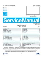
• Dimensions of the copier ... See the figure below. (W698x D778 x H1207 mm)
1207 mm
778 mm
698 mm
e-STUDIO550/650/810 SPECIFICATIONS
1-4
JUNE 2002 © TOSHIBA TEC
1. 2. Accessories
Unpacking/setup instruction
1 pc.
Operator’s Manual
1 pc. (not available for MJD)
PM sticker
1 pc. (for MJD)
Setup report
1 set. (for NAD and MJD)
Customer satisfaction card
1 pc. (for MJD)
Operator’s Manual pocket
1 pc.
Power cable
1 pc. (for ASD, AUD and MJD)
Warranty sheet
1 pc. (for NAD)
Drum
1 pc.
Drum cover
1 pc.
Original feeding tray
1 pc.
Tab paper end guide
1 pc.
* Machine version
NAD:
North America
MJD:
Europe
AUD:
Australia
ASD:
Asia
JUNE 2002 © TOSHIBA TEC
1-5
e-STUDIO550/650/810 SPECIFICATIONS
1. 3. Options
Finisher
MJ-1017, MJ-1018
Hole punch unit
MJ-6003N/E/F/S
Inserter
MJ-7001
Staple cartridge
STAPLE-600/STAPLE-700 (for saddle stitcher)
External large capacity feeder
MP-4003A/L
Key copy counter/Key copy counter socket
MU-8/MU-10
Damp heater kit
MF-6510U/E
Printer controller
GL-1020
Printer board
GA-1140
1. 4. Supplies
Drum
OD-6510
Developer material
D-6510
Toner
PS-ZT6510/PS-ZT6510/PS-ZT-6510D
Toner bag
PS-TB6510/PS-TB6510E
e-STUDIO550/650/810 SPECIFICATIONS
1-6
JUNE 2002 © TOSHIBA TEC
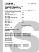
JUNE 2002 © TOSHIBA TEC
Staple cartridge
STAPLE-700
Staple cartridge
STAPLE-600
Finisher
MJ-1018
Finisher
MJ-1017
Hole punch unit
MJ-6003
1-7
Printer board
GA-1140
Printer controller
GL-1020
Inserter
MJ-7001
LCF
MP-4003
Key counter
MU-8
Key counter socke t
MU-10
1. 5. System List
e-STUDIO550/650/810 SPECIFICATIONS
2.
OUTLINE OF THE MACHINE
2. 1. Sectional View
2. 2. Electric Parts Layout
2. 3. Symbols and Functions of Various Components
2. 4. Symbols and Functions of RADF Various Components
2. 5. System Block Layout
2. 6. Disassembly and Replacement of Covers and PC Boards
2. 6. 1. Covers
2. 6. 2. PC boards
2. OUTLINE OF THE MACHINE
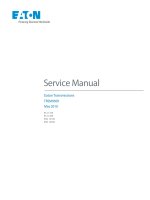
2. 1. Sectional View
[A] Front side view
16
5 4
15
7
6
1 2 3
13
14
12
10
8
11
9
32
23
33
22
40
34
35
41
24
20
17
36
21
25
52
18
43
54
55
19
53
44
37
29
26
27
30
31 28
56
51
38
57
42
39
45
58
47
48
49
46
50
60
59
61
62
63
64
65
69
66
67
70
68
71
JUNE 2002 © TOSHIBA TEC
2-1
e-STUDIO550/650/810 OUTLINE OF THE MACHINE
1
Exposure lamp
41
Thermostat
2
Reflector
42
Pressure roller thermistor
3
Mirror 1
43
Exit roller
4
Mirror 2
44
Reverse/exit switching gate
5
Mirror 3
45
Reverse path roller 1
6
Original glass
46
Reverse path roller 2
7
Lens
47
Transfer roller 1
8
CCD driving PC board
48
Transfer roller 2
9
Scanner control PC board
49
Transfer roller 3
10
Drum
50
Transfer roller 4
11
Drum thermistor
51
Registration roller
12
Charger wire cleaner
52
Bypass transfer roller
13
Main charger
53
Bypass separation roller
14
Discharge LED
54
Bypass feed roller
15
Drum cleaning blade
55
Bypass pickup roller
16
Drum cleaning brush
56
Intermiditate transfer roller
17
Drum recoverly blade
57
1st cassette transfer roller
18
Image quality sensor
58
1st cassette feed roller
19
Drum separation finger
59
1st cassette separation roller
21
Upper developer sleeve (Magnetic roller)
60
1st cassette pickup roller
22
Lower developer sleeve (Magnetic roller)
61
2nd cassette transfer roller
23
Doctor blade
62
2nd cassette feed roller
24
Scattered toner recovery roller
63
2nd cassette separation roller
25
Auto-toner sensor
64
2nd cassette pickup roller
26
Transfer belt driven roller
65
Tandem LCF transfer roller
27
Transfer belt power supply roller
66
Tandem LCF feed roller
28
Transfer belt
67
Tandem LCF separation roller
29
Transfer belt drive roller
68
Tandem LCF cassette pickup roller
30
Transfer belt cleaning blade
69
1st cassette
31
Transfer belt cleaning brush
70
2nd cassette
32
Cleaning web
71
Tandem LCF tray
33
Cleaning web pushing roller
34
Fuser roller
35
Separation finger
36
Fuser exit roller
37
Pressure roller
38
Cleaning roller (metal)
39
Cleaning roller (felt)
40
Fuser roller thermistor
e-STUDIO550/650/810 OUTLINE OF THE MACHINE
2-2
JUNE 2002 © TOSHIBA TEC
[B] Rear side view (Drive system)
4
3
2
1
6
5
9
7
8
10
11
12
13
JUNE 2002 © TOSHIBA TEC
2-3
e-STUDIO550/650/810 OUTLINE OF THE MACHINE
1
Scanner motor
2
Drive pulley
3
Drive belt
4
Driven pulley
5
Drum motor
6
Developer unit motor
7
Registration motor
8
Fuser motor
9
Web motor
10
Exit motor
11
Reverse motor
12
LCF tray-up motor
13
LCF end fence motor
e-STUDIO550/650/810 OUTLINE OF THE MACHINE
2-4
JUNE 2002 © TOSHIBA TEC
2. 2. Electric Parts Layout
[A] Unit construction
Reversing automatic document feeder unit
Scanner unit
Laser unit
Fuser unit
Transfer/Transport unit
Copier unit
Rear side
JUNE 2002 © TOSHIBA TEC
2-5
e-STUDIO550/650/810 OUTLINE OF THE MACHINE
[B] Scanner unit
(B-1) Motor/Exposure lamp
EXP
M31
M1
Rear side
(B-2) Sensor/Switch
S1-5
S1-5
S1-5
S1-5
S1-5
A4 series
S2
Rear side
S1-4
S1-4
S1-4
LT series
S1-4
S2
Rear side
e-STUDIO550/650/810 OUTLINE OF THE MACHINE
2-6
JUNE 2002 © TOSHIBA TEC
(B-3) PC board
INV
CCD
SLG
Rear side
(B-4) Other parts
DHL
DHR
THMO4
Rear side
JUNE 2002 © TOSHIBA TEC
2-7
e-STUDIO550/650/810 OUTLINE OF THE MACHINE
[C] Laser unit
GLV
LDR1
M2
LDR2
SNS
PLG
Rear side
[D] Transfer/Transport unit
THMO3
DHT
FUSE
S5
S4
S3
CLT3
CLT2
CLT1
Rear side
e-STUDIO550/650/810 OUTLINE OF THE MACHINE
2-8
JUNE 2002 © TOSHIBA TEC
[E] Fuser unit
M30
IH
M3
IHCOIL
S6
THM1
THMO2
S7
THM2
THMO1
THM5
THM3
Rear side
JUNE 2002 © TOSHIBA TEC
2-9
e-STUDIO550/650/810 OUTLINE OF THE MACHINE
[F] Copier unit
(F-1) Motor/Fan
M19
M18
M17
M25
M20
M24
M16
M15
M26
M21
M22
M27
M14
M28
M13
M23
M29
M12
M11
M10
M9
M8
M7
M4
M5
M6 M32
Rear side
e-STUDIO550/650/810 OUTLINE OF THE MACHINE
2 - 10
JUNE 2002 © TOSHIBA TEC
(F-2) Clutch/Solenoid
SOL2
SOL1
SOL3
CLT4
CLT5
CLT6
SOL5
CLT8
CLT7
CLT10
CLT9
CLT11
SOL4
Rear side
JUNE 2002 © TOSHIBA TEC
2 - 11
e-STUDIO550/650/810 OUTLINE OF THE MACHINE
(F-3) Sensor/Switch
S52
S14
S17 S16
S15
S19
S49
S50
S51
S21
S26
S27
S28
S29
S32
S33
S34
S35
S25
S38
S39
S40
S41
S18
S24
S20
S31
S30
S37
S36
S10
S23
S11
S22
S42
S13
S43
S44
S47 S45
S12
S46
Rear side
e-STUDIO550/650/810 OUTLINE OF THE MACHINE
2 - 12
JUNE 2002 © TOSHIBA TEC