Radio navigational aids chapter 1
Bạn đang xem bản rút gọn của tài liệu. Xem và tải ngay bản đầy đủ của tài liệu tại đây (1.8 MB, 25 trang )
CHAPTER 1
RADIO DIRECTION FINDER AND RADAR STATIONS
PART I RADIO DIRECTION FINDER STATIONS
100A.
General
Radio bearings may be employed for fixing a ship’s
position in the same manner as other lines of position if
due regard is given to the facts that they, like other lines of
position, may not be absolutely accurate, and that the
bearings are portions of great circles, not rhumb lines.
Radio bearings are obtained using radio direction finder
sets installed on either shore stations or ships, and also by
certain special radiobeacons.
Radio direction finder (RDF)stations are equipped with
apparatus for determining the direction of radio signals
transmitted by ships and other stations.
SECTOR OF CALIBRATION: The sector of calibration
of a direction finder station is the sector around the
receiving coil in which the deviation of radio bearings is
known. In this book, the sectors are measured clockwise
from 000˚ (true north) to 359˚ and are given from the
station to seaward. Bearings which do not fall within the
sector of calibration of the station should be considered
unreliable.
100B.
Accuracy of Bearings Furnished by
Direction Finding Stations
The bearings obtained by RDF stations and reported to
ships are corrected for all determinable errors except the
difference between a great circle and a rhumb line (See sec.
100F.) and are normally accurate within 2˚ for distances
under 150 miles. However, this error may be increased by
various circumstances, some of which are:
STRENGTH OF SIGNALS: The most accurate bearings
result from ships whose signals are steady, clear, and
strong. If the signals are too weak, accurate bearings
cannot be obtained.
TRANSMITTER ADJUSTMENT: The transmitter of
the ship requesting bearings should be tuned carefully to
the frequency of the station. If the tuning is off, it will be
difficult for the station to obtain bearings sufficiently
accurate for navigational purposes.
COASTAL REFRACTION (LAND EFFECT): Bearings
which cut an intervening coastline at an oblique angle, or
cross high intervening land, may produce errors of 4˚ to 5˚.
RDF stations normally know the sectors in which such
refraction may be expected. Such sectors may not be
included in the published sectors of calibration or may be
marked “sectors of uncertain calibration.”
SUNRISE, SUNSET, OR NIGHT EFFECTS: Bearings
obtained from about half an hour before sunset to about
half an hour after sunrise are occasionally unreliable
because of the polarization error introduced. Changes in
the intensity of the signals received occur at sunset and
sunrise.
CAUTION: When RDF stations use such words as
doubtful, approximate, second-class, or the equivalents in
foreign languages, the bearings reported must be treated
with suspicion as considerable error may exist.
DANGER FROM RECIPROCAL BEARINGS: When a
single station furnishes a bearing, there is a possibility of
an error of approximately 180˚, as the operator at the
station cannot always determine on which side of the
station the ship lies. Certain direction finder stations,
particularly those on islands or extended capes, are
equipped to furnish two corrected true bearings for any
observation. Such bearings may differ by approximately
180˚ and whichever bearing is suitable should be used.
CAUTION: Mariners receiving bearings which are
evidently the approximate reciprocal of the correct
bearings should never attempt to correct these bearings by
applying a correction of 180˚, as such a correction would
not include the proper correction for deviation at the
direction finder station. An error as large as 30˚ may be
introduced by an arbitrary correction of 180˚. Ships
receiving bearings requiring an approximate 180˚
correction should request both bearings from the direction
finder station.
100C.
Obligations of Administrations Operating
Direction Finding Stations
The obligations of RDF station operators are given in
Article 35 of the manual for use by the Maritime Mobile
Satellite Services of the International Telecommunications
Union (1992). They include the following:
– Effective and regular service should be maintained, but
no responsibility is accepted for these services.
– Serviced stations shall be advised of doubtful or
unreliable observations.
– RDF station operators shall make daily notification of
any temporary modifications or irregularities in service.
Permanent modifications shall be published as soon as
possible in the relevant notices to mariners.
– All RDF stations shall be able to take bearings on 410
kHz and 500 kHz.
– When RDF service is provided in authorized bands
between 1605 kHz and 2850 kHz, RDF stations
1-3
RADIO DIRECTION FINDER AND RADAR STATIONS
providing that service should be able to take bearings on
2182 kHz.
– When RDF service is provided in the bands between 156
MHz and 174 MHz, the RDF station should be able to
take bearings on VHF 156.8 MHz and VHF digital
selective calling frequency 156.525 MHz.
100D.
Procedure to Obtain Radio Direction
Finder Bearings and Positions
TO OBTAIN A BEARING: The vessel should call the
RDF station or the RDF control station on the designated
watch frequency. Depending on the type of information
wanted, the vessel should transmit the appropriate service
abbreviation(s):
– QTE: What is the true bearing from you (or designated
vessel)?
– QTH: Follows the above abbreviation when the request
is made to a mobile RDF station.
The vessel should also indicate the frequency it will use
to enable its bearing to be taken.
The RDF station called should request the vessel to
transmit for the bearing by means of the service
abbreviation QTG (Will you send two dashes of ten
seconds each (or carrier) followed by your call sign
(repeated __ times) on ___ kHz (or MHz)?).
After shifting, if necessary, to the new transmitting
frequency, the vessel should transmit as instructed by the
RDF station.
The RDF station should determine the direction, sense
(if possible), and classification of the bearing and transmit
to the vessel in the following order:
– QTE.
– Three digits indicating true bearing in degrees from the
RDF station.
– Class of bearing.
– Time of observation.
– If the RDF station is mobile, its own position preceded
by QTH.
When the vessel has received this information, it should
repeat it back, if considered necessary for confirmation.
The RDF station should confirm or correct the information.
When the RDF station is sure the information has been
correctly received, it will transmit AR (end of
transmission). The vessel will respond with AR.
Unless otherwise indicated, the vessel may assume that
the sense of the bearing was indicated. If not, the RDF
station should indicate this or report the bearing and its
reciprocal.
CLASSSIFICATION OF BEARINGS: To estimate the
accuracy and determine the corresponding class of a
bearing:
– An operator should generally, and particularly in the
maritime mobile RDF service on frequencies below 3000
kHz, give the observational characteristics of bearings
shown in the table below.
– The RDF station, when facilities and time permit, may
take into account the probability of error in the bearing.
A bearing is considered as belonging to a particular class
if there is a probability of less than 1 in 20 that the
bearing error would exceed the numerical values
specified for that class in the table below. This
probability should be determined from an analysis of the
five components that make up the total variance of the
bearing (instrumental, site, propagation, random
sampling and observational components).
TO OBTAIN A POSITION (DETERMINED BY TWO
OR MORE RDF STATIONS ORGANIZED AS A
GROUP): The vessel should call the RDF control station
and transmit QTF (Will you give me my position according
to the bearings taken by the RDF stations you control?).
The control station shall reply and, when the RDF
stations are ready, request that the vessel transmit using the
service abbreviation QTG.
Classification of Bearings
Class
Bearing Error
(Degrees)
A
±2˚
B
±5˚
Signal
Strength
very good
or good
fairly good
C
±10˚
weak
D
more than
±10˚
scarcely
perceptible
Bearing
Indication
definite
(sharp null)
blurred
severely
blurred
ill-defined
Observational Characteristics
Fading
Interference
Bearing Swing
(Degrees)
negligible
negligible
less than 3˚
slight
slight
severe
strong
very severe
very strong
1-4
more than 3˚
less than 5˚
more than 5˚
less than 10˚
more than 10˚
Duration of
Observation
adequate
short
very short
inadequate
RADIO DIRECTION FINDER AND RADAR STATIONS
When the position has been determined, the control
station should transmit to the vessel:
– QTF.
– The position in latitude and longitude, or in relation to a
known geographic point.
– Class of position.
– Time of observation.
According to its estimate of the accuracy of the
observations, the control station shall classify the position
in one of the four following classes:
– Class A - positions which the operator may reasonably
expect to be accurate to within 5 nautical miles.
– Class B - positions which the operator may reasonably
expect to be accurate to within 20 nautical miles.
– Class C - positions which the operator may reasonably
expect to be accurate to within 50 nautical miles.
– Class D - positions which the operator may not expect to
be accurate to within 50 nautical miles.
For frequencies above 3000 kHz, where the distance
limits specified in the preceding subparagraph may not be
appropriate, the control station may classify the position in
accordance with current International Telecommunications
Union-Radiocommunications
Sector
(ITU-R)
recommendations.
TO OBTAIN SIMULTANEOUS BEARINGS FROM
TWO OR MORE RDF STATIONS ORGANIZED AS A
GROUP: On a request for bearings, the control station of a
group of RDF stations shall proceed as indicated above. It
then should transmit the bearings observed by each station
of the group, each bearing being preceded by the call sign
of the station which observed it.
100E.
Plotting Radio Bearings
A fix by radio bearings is defined as follows:
Three or more bearings taken simultaneously.
Two bearings and a sounding.
Two bearings and an LOP from a celestial body.
Two bearings and a synchronized air or submarine
signal.
– Two bearings on the same station and the measure of
distance run (solve as if doubling the angle on the bow)
between bearings.
Radio bearings are great circle azimuths (the bearing is
the angle between the meridian of the ship or station taking
the bearing and the great circle, not the rhumb line). They
can be plotted directly upon gnomonic charts, but they
cannot be plotted on a Mercator chart without first being
corrected as described in sec. 100F.
WEIGHT TO BE GIVEN TO RADIO BEARINGS:
Before using a radio bearing for navigational purposes, the
mariner should consider the conditions under which it was
taken and should compare the conditions with those given
in sec. 100B on accuracy.
Land-based marine radiobeacon signals received by
ships may only provide a bearing accuracy relative to
vessel heading of ±3˚ - 10˚. This is not satisfactory for
navigation in restricted channels or harbors.
TRANSMITTERS AND RECEIVERS: Bearings
reported by a direction finding station ashore must be
–
–
–
–
plotted from the geographical position of the receiving
antenna of the station. Bearings taken by a ship on a shore
station must be plotted from the geographical position of
the station’s transmitting antenna.
CAUTION: These two positions are not the same for all
stations.
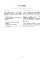
SHIP’S PROBABLE POSITION: As radio bearings are
not absolutely accurate, lines should be drawn on both
sides of each radio bearing at an angular distance from the
bearing equal to the estimated probable error. In the case of
intersecting radio bearings, the ship’s most probable
position is the area enclosed by these outer lines.
In figure 1 the broken lines are radio bearings obtained
on a ship by three radio stations. The solid lines are drawn
at angles of 2˚ from the bearings (it is assumed that all the
bearings are probably accurate within 2˚). The black
triangle in the illustration lies within the 2˚ error of all
three bearings and is the most probable position of the
ship. However, with the possibility that one of the bearings
may be off by more than 2˚, the areas shaded with parallel
lines give other possible positions. If one of the bearings is
suspected to be less accurate, the outer lines should be
offset from this bearing the same number of degrees as the
estimated error, and the area or areas partially enclosed by
these lines should be given less weight than the other areas.
In figure 2, a ship on course 000˚ obtains bearings of
031˚ and 065˚ on a radio station. The lines drawn as long
dashes show the bearings and the continuous lines are their
limits of accuracy. It is assumed that the bearings are both
accurate within 2˚. The lines AB drawn with dashes and
dots are equal to the distance run between bearings. The
distance run is fitted to the lines showing the limits of
accuracy of the bearings. This can be done easily by means
of parallel rulers and dividers. The shaded quadrilateral
shows the ship’s probable position at the time of the second
bearings, if both bearings are accurate within 2˚.
Information on various kinds of land-based
radiobeacons, their accuracy, and use may be found in the
NIMA Lists of Lights (LLPUB110 - 116), Coast Guard
Light Lists (COMDTM165021 - 165027), and “The
American Practical Navigator” (Bowditch) (NVPUB9).
100F.
Radio Bearing Conversion
The table on pg. 1-7 may be used to convert radio or
great circle bearings into Mercator bearings for plotting on
a Mercator chart. The table should be used when the
distance between the ship and station is over 50 miles. The
arguments used to find the correction are the middle
latitude (Lm) and the difference of longitude (DLo)
between the position of the radio station and the dead
reckoning (DR) position of the vessel.
EXAMPLE: A vessel in DR position 56˚04'N, 142˚43'W
takes a bearing on the radiobeacon at Cape Spencer Light
Station at 58˚12.0'N, 136˚38.3'W. The bearing observed is
057.5˚. Find the Mercator bearing.
Lm (to nearest whole degree) = 57˚
DLo (to nearest half degree) = 6˚
With Lm 57˚ and the DLo 6˚ enter the conversion table
and extract the correction 2.5˚. The receiver (ship) is in N
1-5
RADIO DIRECTION FINDER AND RADAR STATIONS
latitude; the transmitter (radiobeacon) is eastward.
Following the rule given at the bottom of the table, the
correction is to be added:
Great circle bearing . . . . . . . . . . . . . . . . . . . . . . . 057.5˚
Correction . . . . . . . . . . . . . . . . . . . . . . . . . . . . . . . +2.5˚
Mercator bearing . . . . . . . . . . . . . . . . . . . . . . . . . 060.0˚
To plot the bearing, add 180˚ to Mercator bearing, giving
240˚, the rhumb line bearing of the ship from the
radiobeacon.
EXAMPLE: A vessel in DR position 42˚20'N, 66˚14'W
requests a bearing from a direction finder station at
42˚08'N, 70˚42'W. The bearing given is 081˚. Find the
Mercator bearing.
Lm (to nearest whole degree) = 42˚
DLo (to nearest half degree) = 4.5˚
With Lm 42˚ and DLo 4.5˚, enter the conversion table
and extract the correction 1.5˚. The receiver (RDF station)
is in N latitude; the transmitter (ship) is eastward.
Following the rule given at the bottom of the table, the
correction is to be added:
Great circle bearing . . . . . . . . . . . . . . . . . . . . . . .081.0˚
Correction. . . . . . . . . . . . . . . . . . . . . . . . . . . . . . . .+1.5˚
Mercator bearing . . . . . . . . . . . . . . . . . . . . . . . . .082.5˚
100G.
Direction Finding Station List
The station list starting on pg. 1-8 shows the names,
positions, and characteristics of radio direction finding
stations.The frequencies used are broken down as follows:
A–Frequency on which station (or control station) keeps
watch.
B–Frequency for transmission of signals on which
bearings are observed.
C– Frequency on which results are transmitted.
Figure 1.
Figure 2.
1-6
RADIO DIRECTION FINDER AND RADAR STATIONS
Mid
Lat.
˚
4
5
6
7
8
9
10
11
12
13
14
15
16
17
18
19
20
21
22
23
24
25
26
27
28
29
30
31
32
33
34
35
36
37
38
39
40
41
42
43
44
45
46
47
48
49
50
51
52
53
54
55
56
57
58
59
60
0.5˚
˚
0.1
.1
.1
.1
.1
.1
.1
.1
.1
.1
.1
.1
.1
.1
.1
.1
.1
.1
.1
.1
.1
.1
.1
.1
.1
.2
.2
.2
.2
.2
.2
.2
.2
.2
.2
.2
.2
.2
.2
.2
.2
.2
.2
.2
.2
.2
.2
.2
.2
0.5˚
Receiver
(latitude)
North
North
Radio Bearing Conversion Table
Correction to be applied to radio bearing to convert to Mercator bearing
Difference of Longitude
1˚
1.5˚
2˚
2.5˚
3˚
3.5˚
4˚
4.5˚
5˚
5.5˚
6˚
6.5˚
˚
˚
˚
˚
˚
˚
˚
˚
˚
˚
˚
˚
0.1
0.1
0.1
0.1
0.2
0.2
0.2
0.2
0.2
0.1
0.1
0.1
.1
.1
.2
.2
.2
.2
.2
.3
.3
.1
.1
.1
.1
.2
.2
.2
.2
.3
.3
.3
.3
.1
.1
.1
.2
.2
.2
.3
.3
.3
.3
.4
.4
.1
.1
.1
.2
.2
.2
.3
.3
.4
.4
.4
.5
.1
.1
.1
.2
.2
.2
.3
.3
.4
.4
.5
.5
.1
.1
.1
.2
.2
.3
.4
.4
.4
.5
.5
.6
.1
.1
.2
.2
.3
.3
.4
.4
.5
.5
.6
.6
.1
.1
.2
.3
.3
.4
.4
.5
.5
.6
.6
.7
.1
.2
.2
.3
.3
.4
.4
.5
.6
.6
.7
.7
.1
.2
.2
.3
.4
.4
.5
.6
.6
.7
.7
.8
.1
.2
.3
.3
.4
.4
.5
.6
.6
.7
.8
.8
.1
.2
.3
.4
.4
.5
.6
.6
.7
.8
.8
.9
.2
.2
.3
.4
.4
.5
.6
.6
.7
.8
.9
1.0
.2
.2
.3
.4
.5
.5
.6
.7
.8
.8
.9
1.0
.2
.2
.3
.4
.5
.6
.6
.7
.8
.9
1.0
1.1
.2
.2
.3
.4
.5
.6
.7
.8
.8
.9
1.0
1.1
.2
.3
.4
.5
.5
.6
.7
.8
.9
1.0
1.1
1.2
.2
.3
.4
.5
.6
.6
.8
.8
.9
1.0
1.1
1.2
.2
.3
.4
.5
.6
.7
.8
.9
1.0
1.1
1.2
1.3
.2
.3
.4
.5
.6
.7
.8
.9
1.0
1.1
1.2
1.3
.2
.3
.4
.5
.6
.7
.8
1.0
1.1
1.2
1.3
1.4
.2
.3
.4
.6
.6
.8
.9
1.0
1.1
1.2
1.3
1.4
.2
.3
.4
.6
.7
.8
.9
1.0
1.1
1.2
1.4
1.5
.2
.4
.5
.6
.7
.8
.9
1.1
1.2
1.3
1.4
1.5
.2
.4
.5
.6
.7
.8
1.0
1.1
1.2
1.3
1.4
1.6
.2
.4
.5
.6
.8
.9
1.0
1.1
1.2
1.4
1.5
1.6
.2
.4
.5
.6
.8
.9
1.0
1.2
1.3
1.4
1.6
1.7
.3
.4
.5
.7
.8
.9
1.1
1.2
1.3
1.4
1.6
1.7
.3
.4
.6
.7
.8
1.0
1.1
1.2
1.4
1.5
1.6
1.8
.3
.4
.6
.7
.8
1.0
1.1
1.2
1.4
1.5
1.7
1.8
.3
.4
.6
.7
.9
1.0
1.2
1.3
1.4
1.6
1.7
1.9
.3
.4
.6
.7
.9
1.0
1.2
1.3
1.5
1.6
1.8
1.9
.3
.4
.6
.8
.9
1.1
1.2
1.4
1.5
1.6
1.8
2.0
.3
.5
.6
.8
.9
1.1
1.2
1.4
1.5
1.7
1.8
2.0
.3
.5
.6
.8
1.0
1.1
1.2
1.4
1.6
1.7
1.9
2.1
.3
.5
.6
.8
1.0
1.1
1.3
1.4
1.6
1.8
1.9
2.1
.3
.5
.6
.8
1.0
1.2
1.3
1.5
1.6
1.8
2.0
2.1
.3
.5
.7
.8
1.0
1.2
1.3
1.5
1.7
1.8
2.0
2.2
.3
.5
.7
.8
1.0
1.2
1.4
1.5
1.7
1.9
2.1
2.2
.4
.5
.7
.9
1.1
1.2
1.4
1.6
1.7
1.9
2.1
2.2
.4
.5
.7
.9
1.1
1.2
1.4
1.6
1.8
2.0
2.1
2.3
.4
.5
.7
.9
1.1
1.3
1.4
1.6
1.8
2.0
2.2
2.3
.4
.6
.7
.9
1.1
1.3
1.5
1.7
1.8
2.0
2.2
2.4
.4
.6
.8
.9
1.1
1.3
1.5
1.7
1.8
2.1
2.2
2.4
.4
.6
.8
1.0
1.1
1.3
1.5
1.7
1.9
2.1
2.3
2.5
.4
.6
.8
1.0
1.1
1.3
1.5
1.7
1.9
2.1
2.3
2.5
.4
.6
.8
1.0
1.2
1.4
1.6
1.8
2.0
2.1
2.3
2.5
.4
.6
.8
1.0
1.2
1.4
1.6
1.8
2.0
2.2
2.4
2.6
.4
.6
.8
1.0
1.2
1.4
1.6
1.8
2.0
2.2
2.4
2.6
.4
.6
.8
1.0
1.2
1.4
1.6
1.8
2.0
2.2
2.4
2.6
.4
.6
.8
1.0
1.2
1.4
1.6
1.8
2.1
2.2
2.4
2.7
.4
.6
.8
1.0
1.2
1.4
1.7
1.9
2.1
2.3
2.5
2.7
.4
.6
.8
1.1
1.2
1.5
1.7
1.9
2.1
2.3
2.5
2.7
.4
.6
.8
1.1
1.3
1.5
1.7
1.9
2.1
2.3
2.6
2.8
.4
.6
.8
1.1
1.3
1.5
1.7
1.9
2.2
2.4
2.6
2.8
.4
.6
.9
1.1
1.3
1.5
1.7
2.0
2.2
2.4
2.6
2.8
1˚
1.5˚
2˚
2.5˚
3˚
3.5˚
4˚
4.5˚
5˚
5.5˚
6˚
6.5˚
Transmitter (direction
Correction
Receiver (latitude)
Transmitter (direction
from receiver)
Sign
from receiver)
Eastward
+
South
Eastward
Westward
—
South
Westward
1-7
Mid
Lat.
7˚
˚
0.2
.3
.4
.4
.5
.6
.6
.7
.7
.8
.8
.9
1.0
1.0
1.1
1.1
1.2
1.2
1.3
1.4
1.4
1.5
1.5
1.6
1.6
1.7
1.8
1.8
1.8
1.9
2.0
2.0
2.1
2.1
2.2
2.2
2.2
2.3
2.3
2.4
2.4
2.5
2.5
2.6
2.6
2.6
2.7
2.7
2.8
2.8
2.8
2.9
2.9
2.9
3.0
3.0
3.0
7˚
7.5˚
˚
0.3
.3
.4
.5
.5
.6
.6
.7
.8
.8
.9
1.0
1.0
1.1
1.2
1.2
1.3
1.4
1.4
1.5
1.5
1.6
1.6
1.7
1.8
1.8
1.9
1.9
2.0
2.0
2.1
2.2
2.2
2.2
2.3
2.4
2.4
2.5
2.5
2.6
2.6
2.6
2.7
2.8
2.8
2.8
2.9
2.9
3.0
3.0
3.0
3.1
3.1
3.2
3.2
3.2
3.2
7.5˚
Correction
Sign
—
+
˚
4
5
6
7
8
9
10
11
12
13
14
15
16
17
18
19
20
21
22
23
24
25
26
27
28
29
30
31
32
33
34
35
36
37
38
39
40
41
42
43
44
45
46
47
48
49
50
51
52
53
54
55
56
57
58
59
60
RADIO DIRECTION FINDER AND RADAR STATIONS
(1)
No.
(2)
Name
(3)
Type
(4)
Position
Rx
(5)
Frequency
(6)
Range
(7)
Procedure
(8)
Remarks
Tx
CANADA
The VHF direction finding stations of Canada are for emergency use only. All stations are remotely controlled by a Marine
Communications and Traffic Services Center (MCTS). The following details of operation are common to all of these stations:
A. Ch.16.
B. Ch.16 (distress only).
C. Ch.16 (distress only).
1001 Cap-aux-Meules.
RDF
47 23 14 N
61 51 40 W
MCTS Riviere-au-Renard (VCG).
1001.1 Cap des Rosiers.
2-4326
RDF
48 51 40 N
64 12 53 W
MCTS Riviere-au-Renard (VCG).
RDF
48 22 55 N
70 41 25 W
MCTS Quebec (VCC).
RDF
48 08 00 N
66 07 20 W
MCTS Riviere-au-Renard (VCG).
RDF
48 50 02 N
64 15 30 W
MCTS Riviere-au-Renard (VCG).
RDF
47 03 54 N
55 51 04 W
MCTS Placentia (VCP).
RDF
48 54 51 N
67 06 38 W
MCTS Les Escoumins (VCF).
RDF
50 30 00 N
59 29 17 W
MCTS Riviere-au-Renard (VCG).
RDF
50 16 15 N
63 40 44 W
MCTS Riviere-au-Renard (VCG).
RDF
50 12 57 N
60 41 13 W
MCTS Riviere-au-Renard (VCG).
RDF
47 21 26 N
61 55 36 W
MCTS Riviere-au-Renard (VCG).
RDF
50 17 21 N
66 18 43 W
MCTS Les Escoumins (VCF).
RDF
46 48 45 N
71 09 33 W
MCTS Quebec (VCC).
RDF
48 19 03 N
69 25 13 W
MCTS Les Escoumins (VCF).
1001.75 Mont Belair.
2-4326
RDF
46 49 22 N
71 29 45 W
MCTS Quebec (VCC).
1001.8 Mont Joli.
2-4326
RDF
48 36 30 N
68 13 45 W
MCTS Les Escoumins (VCF).
1001.85 Mont-Louis.
2-4326
RDF
49 12 48 N
65 46 27 W
MCTS Les Escoumins (VCF).
1001.9 Montmagny.
2-4326
RDF
46 55 42 N
70 30 45 W
MCTS Quebec (VCC).
1001.95 Natashquan.
2-4326
RDF
50 08 40 N
61 48 00 W
MCTS Riviere-au-Renard (VCG).
1002 Newport.
2-4326
RDF
48 13 37 N
64 47 33 W
MCTS Riviere-au-Renard (VCG).
1002.1 Pointe Heath.
2-4326
RDF
49 05 05 N
61 42 09 W
MCTS Riviere-au-Renard (VCG).
RDF
49 00 29 N
64 24 00 W
MCTS Riviere-au-Renard (VCG).
1001.15 Cap Est.
2-4326
1001.2 Carleton.
2-4326
1001.25 Forillon.
2-4326
1001.3 Fortune Head.
2-4326
1001.35 Grosses-Roches.
2-4326
1001.4 Harrington Harbor.
2-4326
Seasonal operation: April 1-December 31.
1001.45 Havre St.-Pierre.
2-4326
1001.5 La Romaine.
2-4326
Seasonal operation: April 1-December 31.
1001.55 La Verniere.
1001.6 Lac D'aigle (Sept
2-4326 Iles).
1001.65 Lauzon.
2-4326
1001.7 Les Escoumins.
1002.15 Riviere-au-Renard.
2-4326
1-8
RADIO DIRECTION FINDER AND RADAR STATIONS
(1)
No.
(2)
Name
(3)
Type
(4)
Position
Rx
1002.2 Riviere du Loup.
2-4326
(5)
Frequency
(6)
Range
(7)
Procedure
(8)
Remarks
Tx
RDF
47 45 26 N
69 36 14 W
MCTS Quebec (VCC).
RDF
48 12 45 N
69 52 15 W
MCTS Quebec (VCC).
RDF
46 23 50 N
72 27 17 W
MCTS Quebec (VCC).
1002.35 Twillingate.
2-4326
RDF
49 41 16 N
54 48 03 W
MCTS St. Anthony (VCM).
1002.36 Banks.
RDF
44 28 30 N
80 20 56 W
MCTS Thunder Bay (VBA).
1002.37 Brougham.
RDF
43 55 13 N
79 06 51 W
MCTS Prescott (VBR).
1002.38 Cape Croker.
RDF
44 57 30 N
80 57 53 W
MCTS Thunder Bay (VBA).
RDF
44 04 02 N
78 12 38 W
MCTS Prescott (VBR).
RDF
45 33 50 N
80 19 18 W
MCTS Thunder Bay (VBA).
RDF
45 09 42 N
81 29 22 W
MCTS Thunder Bay (VBA).
RDF
43 29 41 N
79 43 47 W
MCTS Prescott (VBR).
1002.25 Sacre Coeur.
2-4326
1002.3 Trois-Rivieres.
2-4326
1002.4 Cobourg.
1002.45 Pointe au Baril.
1002.5 Tobermory.
1002.55 Trafalgar.
Seasonal operation: April 1-December 31.
1002.6 Barry Inlet.
2-3510
RDF
52 34 30 N
131 45 13 W
MCTS Prince Rupert (VAJ).
RDF
51 35 21 N
128 00 43 W
MCTS Prince Rupert (VAJ).
RDF
53 09 33 N
131 59 47 W
MCTS Prince Rupert (VAJ).
RDF
54 31 16 N
130 54 55 W
MCTS Prince Rupert (VAJ).
RDF
52 34 45 N
128 33 45 W
MCTS Prince Rupert (VAJ).
RDF
53 15 46 N
129 11 42 W
MCTS Prince Rupert (VAJ).
1002.9 Mount Hays.
2-3510
RDF
54 17 12 N
130 18 49 W
MCTS Prince Rupert (VAJ).
1002.95 Naden Harbor.
2-3510
RDF
53 57 18 N
132 56 30 W
MCTS Prince Rupert (VAJ).
RDF
53 15 08 N
132 32 31 W
MCTS Prince Rupert (VAJ).
1002.65 Calvert Island.
2-3510
1002.7 Cumshewa.
2-3510
1002.75 Dundas Island.
2-3510
1002.8 Klemtu.
2-3510
1002.85 Mount Gil.
2-3510
1003 Van Inlet.
2-3510
NORWAY
1005 Rogaland (LGQ).
2-0727
RDF
58 48 44 N 58 56 48 N
5 40 16 E
5 42 16 E
A. 500 kHz, A1A, A2A;
2182kHz, A3E.
B. 255-535 kHz band,
A1A, A2A.
1600-3200 kHz band,
A3E.
C. 516 kHz, A1A, A2A,
1.0kW; 1729 kHz, A3E,
0.5kW.
1006 Lista Lt. (LGZ).
2-0722
RDF
58 07 03 N
6 34 14 E
Call Farsund Radio (LGZ).
1007 Hillersoy (LGL).
2-0752
RDF
61 16 45 N
4 37 26 E
Call Floro Radio (LGL).
1-9
CALIBRATED SECTOR: 100-009°.
RADIO DIRECTION FINDER AND RADAR STATIONS
(1)
No.
(2)
Name
(3)
Type
(4)
Position
Rx
(5)
Frequency
(6)
Range
(7)
Procedure
(8)
Remarks
Tx
SWEDEN
1015 Goteborg (SAG).
2-0665
RDF
57 24 55 N 57 27 55 N
11 56 15 E 11 56 05 E
A. 500 kHz, A2A; 2037,
2182 kHz, A3E.
B. 410, 500 kHz, A2A;
1605-3800 kHz band,
A3E. Pref. freq.: 2182
kHz.
C. 450, 500 kHz, A2A, 2.0
kW; 1785, 2182 kHz,
A3E, 2.0 kW.
Ship's call sign is transmitted
for 50 sec., followed by 10 sec.
dash.
CALIBRATED SECTOR: 159-345°.
CHARGES: 3.5 gold francs.
DENMARK
1020 Blavand (OXB).
2-0311
RDF
55 33 36 N 55 33 14 N
8 05 55 E
8 06 58 E
A. 500 kHz, A2A; 2076,
2182 kHz, J3E, H3E.
B. 410, 500* kHz, A2A;
2076, 2182* kHz, H3E.
C. 429, 500* kHz, A1A,
A2A, 0.9 kW; 1813,
2182* kHz, J3E, H3E,
0.5 kW.
CHARGES: 1 Special Drawing Right
(SDR) per bearing.
57 44 12 N 57 44 04 N
10 36 52 E 10 34 23 E
A. 500 kHz, A2A; 1988,
2182 kHz, J3E, H3E.
B. 410, 500* kHz, A1A,
A2A; 1988, 2182* kHz,
H3E.
C. 464, 500* kHz, A1A,
A2A, 0.25 kW; 1701,
2182* kHz, J3E, H3E,
0.25 kW.
CHARGES: 1 SDR per bearing.
55 30 57 N 55 50 20 N
11 04 55 E 11 25 26 E
A. 500 kHz, A2A; 2069,
2182 kHz, J3E, H3E.
B. 410, 500* kHz, A1A,
A2A; 2069, 2182* kHz,
H3E.
C. 487, 500* kHz, A1A,
A2A, 0.75 kW; 1687,
2182* kHz, J3E, H3E,
1.5 kW.
CHARGES: 1 SDR per bearing.
55 06 07 N 55 02 33 N
14 42 21 E 15 06 57 E
A. 1995, 2182 kHz, J3E,
H3E.
B. 1995, 2182 kHz, J3E,
H3E.
C. 2182*, 2586 kHz, J3E,
H3E, 0.07 kW.
CHARGES: 1 SDR per bearing.
*NOTE: In case of distress only.
1021 Skagen (OXP).
2-0327
RDF
*NOTE: In case of distress only.
1022 Lyngby, Reerso
2-0357 (OXZ).
RDF
*NOTE: In case of distress only.
1023 Ronne (OYE).
2-0391
RDF
*NOTE: In case of distress only.
UNITED KINGDOM
The VHF direction finding stations of the United Kingdom are for emergency use only. Except for Guernsey and Jersey, all are
remotely controlled by a HM Coast Guard Maritime Rescue Coordination Center or Sub-Center (MRCC/MRSC). The following
details of operation are common to all of these stations:
A. Ch.16.
B. Ch.16 (distress only).
Ch.67. Ch.82 (Jersey
only).
C. Ch.16 (distress only).
Ch.67. Ch.82 (Jersey
only).
1055 Barra.
2-0001
RDF
57 00 48 N
7 30 25 W
MRSC Stornoway.
1060 Bawdsey.
2-0001
RDF
51 59 36 N
1 25 00 E
MRSC Thames.
1 - 10
RADIO DIRECTION FINDER AND RADAR STATIONS
(1)
No.
(2)
Name
(3)
Type
(4)
Position
Rx
(5)
Frequency
(6)
Range
(7)
Procedure
(8)
Remarks
Tx
1065 Berry Head.
2-0001
RDF
50 23 58 N
3 29 03 W
MRSC Brixham.
1066 Boniface.
2-0001
RDF
50 36 13 N
1 12 02 W
MRSC Solent.
1070 Compass Head.
2-0001
RDF
59 52 03 N
1 16 18 W
MRSC Shetland.
1072 Crosslaw.
2-0001
RDF
55 54 30 N
2 12 12 W
MRSC Forth.
1073 Cullercoats.
2-0001
RDF
55 04 00 N
1 28 00 W
MRSC Humber.
1075 Dunnet Head.
2-0001
RDF
58 40 18 N
3 22 31 W
MRCC Aberdeen.
1080 Easington.
2-0001
RDF
53 39 08 N
0 05 57 E
MRSC Humber.
1082 East Prawle.
2-0001
RDF
50 13 06 N
3 42 30 W
MRSC Brixham.
1086 Fairlight.
2-0001
RDF
50 52 11 N
0 38 44 E
MRCC Dover.
1087 Fife Ness.
2-0001
RDF
56 16 47 N
2 35 15 W
MRSC Forth.
1088 Flamborough.
2-0001
RDF
54 07 05 N
0 05 07 W
MRSC Humber.
1089 Great Ormes Head.
2-0001
RDF
53 19 59 N
3 51 07 W
MRSC Holyhead.
1090 Grove Point.
2-0001
RDF
50 32 56 N
2 25 12 W
MRSC Portland.
1090.5 Guernsey.
2-0155
RDF
49 26 16 N
2 35 46 W
1091 Hartland.
2-0001
RDF
51 01 12 N
4 31 19 W
MRCC Swansea.
1091.2 Hartlepool.
2-0001
RDF
54 41 47 N
1 10 28 W
MRSC Humber.
1092 Hengistbury Head.
2-0001
RDF
50 42 57 N
1 45 38 W
MRSC Portland.
1093 Inverbervie.
2-0001
RDF
56 51 06 N
2 15 39 W
MRSC Forth.
1093.5 Jersey.
2-0155
RDF
49 10 51 N
2 14 18 W
1094 Kilchiaran.
2-0001
RDF
55 45 54 N
6 27 11 W
MRCC Clyde.
1094.1 Lands End.
2-0001
RDF
50 08 08 N
5 38 11 W
MRCC Falmouth.
1094.2 Langdon Battery.
2-0001
RDF
51 07 56 N
1 20 41 E
MRCC Dover.
1 - 11
RADIO DIRECTION FINDER AND RADAR STATIONS
(1)
No.
(2)
Name
(3)
Type
(4)
Position
Rx
(5)
Frequency
(6)
Range
(7)
Procedure
(8)
Remarks
Tx
1094.5 Law Hill.
2-0001
RDF
55 41 46 N
4 50 28 W
MRCC Clyde.
1095 Lizard.
2-0001
RDF
49 57 36 N
5 12 04 W
MRCC Falmouth.
1095.5 Lowestoft.
2-0001
RDF
52 28 36 N
1 42 12 E
MRCC Yarmouth.
1096 Newhaven.
2-0001
RDF
50 46 54 N
0 03 08 E
MRSC Solent.
1097 Newton.
2-0001
RDF
55 31 01 N
1 37 06 W
MRSC Humber.
1098 North Foreland.
2-0001
RDF
51 22 30 N
1 26 49 E
MRCC Dover.
1098.2 Noss Head.
2-0001
RDF
58 28 48 N
3 03 00 W
MRCC Aberdeen.
1098.5 Orlock Head.
2-0175
RDF
54 40 25 N
5 34 58 W
MRSC Belfast.
1105 Rame Head.
2-0001
RDF
50 18 59 N
4 13 06 W
MRSC Brixham.
1105.2 Rhiw.
2-0001
RDF
52 49 59 N
4 37 41 W
MRSC Holyhead.
1106 Rodel.
2-0001
RDF
57 44 54 N
6 57 24 W
MRSC Stornoway.
1108 St. Ann's Head.
2-0001
RDF
51 40 58 N
5 10 31 W
MRSC Milford Haven.
1109 St. Mary's, Isles of
2-0001 Scilly.
RDF
49 55 42 N
6 18 10 W
MRCC Falmouth.
1110 Sandwick.
2-0001
RDF
58 12 39 N
6 21 16 W
MRSC Stornoway.
1115 Selsey.
2-0001
RDF
50 43 49 N
0 48 12 W
MRSC Solent.
1116 Shoeburyness.
2-0001
RDF
51 31 20 N
0 46 41 E
MRSC Thames.
1117 Skegness.
2-0001
RDF
53 09 00 N
0 21 00 E
MRCC Yarmouth.
1120 Snaefell.
2-0001
RDF
54 15 50 N
4 27 40 W
MRSC Liverpool.
1150 Tiree.
2-0001
RDF
56 30 37 N
6 57 41 W
MRCC Clyde.
1155 Trevose Head.
2-0001
RDF
50 32 54 N
5 01 53 W
MRCC Falmouth.
1160 Trimingham.
2-0001
RDF
52 54 34 N
1 20 36 E
MRCC Yarmouth.
1165 Tynemouth.
2-0001
RDF
50 01 05 N
1 24 54 W
MRSC Humber.
1 - 12
RADIO DIRECTION FINDER AND RADAR STATIONS
(1)
No.
(2)
Name
(3)
Type
(4)
Position
Rx
(5)
Frequency
(6)
Range
(7)
Procedure
(8)
Remarks
Tx
1170 Walney Island.
2-0001
RDF
54 06 37 N
3 16 00 W
MRSC Liverpool.
1171 West Torr.
2-0175
RDF
55 11 54 N
6 05 36 W
MRSC Belfast.
1172 Whitby.
2-0001
RDF
54 29 24 N
0 36 15 W
MRSC Humber.
1175 Wideford Hill.
2-0001
RDF
58 59 17 N
3 01 24 W
MRSC Shetland.
1180 Windyhead.
2-0001
RDF
57 38 54 N
2 14 30 W
MRCC Aberdeen.
FRANCE
The VHF direction finding stations of France are for emergency use only. The following details of operation are common to all of
these stations:
CROSS Stations:
A. Ch.11, 16 (67 when 11
is in use for distress
traffic).
B. Ch.11, 16 (67).
C. Ch.11, 16 (67).
Signal and lookout
stations:
A. Ch.16 and 7 additional
frequencies (swept by
scanner) from Ch.1-29,
36, 39, 48, 50, 52, 55,
56, 60-88.
B. Ch.11, 16.
C. Ch.11, 16.
1182 Gris-Nez.
2-0815
RDF
50 52 12 N
1 35 00 E
Controlled by CROSS.
1182.1 Jobourg.
2-0815
RDF
49 41 06 N
1 54 36 W
Controlled by CROSS.
1182.2 Roches-Douvres.
2-0815
RDF
49 06 30 N
2 48 48 W
Controlled by CROSS-Jobourg.
1182.3 Dunkerque.
2-0815
RDF
51 03 24 N
2 20 24 E
Controlled by signal station.
RDF
50 57 11 N
1 46 23 E
Controlled by signal station.
1182.4 Boulogne.
2-0815
RDF
50 44 00 N
1 36 00 E
Controlled by Signal Station. Day
service only.
1182.5 Ault.
2-0815
RDF
50 06 30 N
1 27 30 E
Controlled by Signal Station. Day
service only.
1182.6 Dieppe.
2-0815
RDF
49 56 00 N
1 05 12 E
Controlled by signal station. Day
service only.
1182.7 Fecamp.
2-0815
RDF
49 46 06 N
0 22 12 E
Controlled by signal station.
1182.8 La Heve.
2-0815
RDF
49 30 36 N
0 04 12 E
Controlled by signal station.
1182.35 Sangatte.
2-0815
1 - 13
RADIO DIRECTION FINDER AND RADAR STATIONS
(1)
No.
(2)
Name
(3)
Type
(4)
Position
Rx
(5)
Frequency
(6)
Range
(7)
Procedure
(8)
Remarks
Tx
1182.9 Villerville.
2-0815
RDF
49 23 12 N
0 06 30 E
Controlled by signal station. Day
service only.
1183 Port-en-Bessin.
2-0815
RDF
49 21 06 N
0 46 18 W
Controlled by signal station.
RDF
49 34 30 N
1 16 30 W
Controlled by signal station. Day
service only.
RDF
49 41 54 N
1 15 54 W
Controlled by signal station.
RDF
49 41 42 N
1 28 12 W
Controlled by signal station. Day
service only.
RDF
49 39 30 N
1 37 54 W
Controlled by lookout station.
1183.25 La Hague.
2-0815
RDF
49 43 36 N
1 56 18 W
Controlled by signal station. Day
service only.
1183.3 Carteret.
2-0815
RDF
49 22 24 N
1 48 18 W
Controlled by signal station. Day
service only.
RDF
48 50 06 N
1 36 54 W
Controlled by signal station. Day
service.
RDF
48 27 36 N
5 07 48 W
Controlled by CROSS-Corsen.
RDF
48 42 36 N
1 50 36 W
Controlled by signal station. Day
service only.
RDF
48 38 36 N
2 14 42 W
Controlled by signal station. Day
service only.
RDF
48 39 18 N
2 49 30 W
Controlled by signal station.
RDF
48 51 18 N
3 00 06 W
Controlled by signal station. Day
service only.
RDF
48 49 30 N
3 28 12 W
Controlled by signal station.
RDF
48 44 48 N
4 00 36 W
Controlled by signal station. Day
service only.
RDF
48 40 36 N
4 19 42 W
Controlled by signal station.
RDF
48 27 36 N
5 07 42 W
Controlled by signal station. Day
service only (24 hr. service provided
by nearby CROSS station).
1183.05 Saint-Vaast.
2-0815
1183.1 Barfleur.
2-0815
1183.15 Levy.
2-0815
1183.2 Homet.
2-0815
1183.35 Le Roc.
2-0815
1183.4 Creac'h (Ile
2-0815 d'Ouessant).
1183.45 Grouin (Cancale).
2-0815
1183.5 Saint-Cast.
2-0815
1183.55 S. Quay Portrieux.
2-0815
1183.6 Brehat.
2-0815
1183.65 Ploumanach.
2-0815
1183.7 Batz.
2-0815
1183.75 Brignogan.
2-0815
1183.8 Creac'h (Ile
2-0815 d'Ouessant).
1 - 14
RADIO DIRECTION FINDER AND RADAR STATIONS
(1)
No.
(2)
Name
(3)
Type
(4)
Position
Rx
1183.85 Saint-Mathieu.
2-0815
(5)
Frequency
(6)
Range
(7)
Procedure
(8)
Remarks
Tx
RDF
48 19 48 N
4 46 12 W
Controlled by lookout station.
RDF
48 16 48 N
4 37 30 W
Controlled by signal station. Day
service only.
RDF
48 10 12 N
4 33 00 W
Controlled by signal station. Day
service only.
RDF
48 02 18 N
4 43 48 W
Controlled by signal station.
1184.05 Penmarc'h.
2-0815
RDF
47 47 54 N
4 22 24 W
Controlled by signal station.
1184.1 Beg-Meil.
2-0815
RDF
47 51 18 N
3 58 24 W
Controlled by signal station. Day
service only.
RDF
47 39 48 N
3 12 00 W
Controlled by CROSS.
1184.2 Beg Melen.
2-0815
RDF
47 39 12 N
3 30 06 W
Controlled by signal station. Day
service only.
1184.25 Port-Louis.
2-0815
RDF
47 42 36 N
3 21 48 W
Controlled by lookout station.
RDF
47 29 42 N
3 07 30 W
Controlled by signal station. Day
service only.
1184.35 Taillefer.
2-0815
RDF
47 21 48 N
3 09 00 W
Controlled by signal station. Day
service only.
1184.4 Le Talut.
2-0815
RDF
47 17 42 N
3 13 00 W
Controlled by signal station. Day
service only.
RDF
47 22 30 N
2 33 24 W
Controlled by signal station. Day
service only.
RDF
47 14 06 N
2 17 48 W
Controlled by signal station.
1184.55 Saint-Sauveur.
2-0815
RDF
46 41 42 N
2 18 48 W
Controlled by signal station. Day
service only.
1184.6 Les Baleines.
2-0815
RDF
46 14 36 N
1 33 42 W
Controlled by signal station. Day
service only.
1184.65 Chassiron.
2-0815
RDF
46 02 48 N
1 24 30 W
Controlled by signal station. Day
service only.
1184.7 La Coubre.
2-0815
RDF
45 41 54 N
1 13 24 W
Controlled by signal station.
1183.9 Toulinguet
2-0815 (Camaret).
1183.95 Cap de la Chevre.
2-0815
1184 Pointe du Raz.
2-0815
1184.15 Etel.
2-0815
1184.3 Saint-Julien.
2-0815
1184.45 Piriac.
2-0815
1184.5 Chemoulin.
2-0815
1 - 15
RADIO DIRECTION FINDER AND RADAR STATIONS
(1)
No.
(2)
Name
(3)
Type
(4)
Position
Rx
1184.75 Pointe de Grave.
2-0815
(5)
Frequency
(6)
Range
(7)
Procedure
(8)
Remarks
Tx
RDF
45 34 18 N
1 03 54 W
Controlled by signal station. Day
service only.
1184.8 Cap Ferret.
2-0815
RDF
44 37 30 N
1 15 00 W
Controlled by signal station. Day
service only.
1184.82 Messanges.
2-0815
RDF
43 48 48 N
1 23 54 W
Controlled by signal station. Day
service only.
1184.85 Socoa.
2-0815
RDF
43 23 18 N
1 41 06 W
Controlled by signal station.
1185.5 La Garde.
2-1040
RDF
43 06 18 N
5 59 30 E
Controlled by CROSS.
1185.6 Cap Bear.
2-1040
RDF
42 30 48 N
3 08 00 E
Controlled by signal station.
1185.7 Cap Leucate.
2-1040
RDF
42 55 06 N
3 03 42 E
Controlled by signal station. Day
service only.
1185.8 Sete.
2-1040
RDF
43 23 48 N
3 41 30 E
Controlled by signal station.
1185.9 L'Espiguette.
2-1040
RDF
43 29 18 N
4 08 30 E
Controlled by signal station. Day
service only.
1186 Cap Couronne.
2-1040
RDF
43 20 06 N
5 03 18 E
Controlled by signal station.
1186.1 Pomegues.
2-1040
RDF
43 16 00 N
5 17 42 E
Controlled by signal station. Day
service only.
1186.2 Bec de L'Aigle.
2-1040
RDF
43 10 30 N
5 34 36 E
Controlled by signal station. Day
service only.
1186.3 Cap Cepet.
2-1040
RDF
43 04 48 N
5 56 30 E
Controlled by lookout station.
1186.4 Porquerolles.
2-1040
RDF
43 00 00 N
6 13 42 E
Controlled by signal station. Day
service only.
1186.5 Cap Camarat.
2-1040
RDF
43 12 06 N
6 40 30 E
Controlled by signal station. Day
service only.
1186.6 Cap du Dramont.
2-1040
RDF
43 24 48 N
6 51 12 E
Controlled by signal station. Day
service only.
1186.7 La Garoupe.
2-1040
RDF
43 34 00 N
7 08 12 E
Controlled by signal station. Day
service only.
1186.8 Cap Ferrat.
2-1040
RDF
43 41 12 N
7 19 30 E
Controlled by signal station. Day
service only.
1 - 16
RADIO DIRECTION FINDER AND RADAR STATIONS
(1)
No.
(2)
Name
(3)
Type
(4)
Position
Rx
(5)
Frequency
(6)
Range
(7)
Procedure
(8)
Remarks
Tx
1186.9 Cap Corse.
2-1040
RDF
43 00 18 N
9 21 36 E
Controlled by signal station. Day
service only.
1187 Ile Rousse.
2-1040
RDF
42 37 54 N
8 55 24 E
Controlled by signal station. Day
service only.
1187.1 La Parata.
2-1040
RDF
41 54 06 N
8 36 48 E
Controlled by signal station. Day
service only.
1187.2 Pertusato.
2-1040
RDF
41 22 24 N
9 10 42 E
Controlled by signal station.
1187.3 La Chiappa.
2-1040
RDF
41 35 36 N
9 21 54 E
Controlled by signal station. Day
service only.
1187.4 Alistro.
2-1040
RDF
42 15 36 N
9 32 30 E
Controlled by signal station. Day
service only.
1187.5 Sagro.
2-1040
RDF
42 47 48 N
9 29 24 E
Controlled by signal station. Day
service only.
BULGARIA
1187.6 Maslen Nos Lt.
2-1279
1187.61 Nos Galata Lt.
2-1282
RDF
42 18 30 N
27 47 42 E
297.5 kHz, A2A.
10
On request to Hydrographic
Service, Varna.
Transmits MN.
RDF
43 10 17 N
27 56 49 E
297.5 kHz, A2A.
5
On request to Hydrographic
Service, Varna.
Transmits DG.
PAKISTAN
1188 Karachi (ASK).
2-2147
RDF
24 52 44 N 24 51 05 N
67 09 50 E 67 02 32 E
A. 410, 500 kHz, A1A.
B. 410, 500 kHz, A1A.
C. 410, 500 kHz, A1A,
A2A, 1.5 kW.
INDIA
1188.1 Calcutta (VWC).
2-2200
RDF
22 28 56 N 22 38 37 N
88 21 26 E 88 23 07 E
A. 500 kHz, A1A, A2A.
B. 500, 410 kHz, A1A.
C. 500 kHz, A1A, 1.5 kW.
1 - 17
CALIBRATED SECTOR: 360°.
RADIO DIRECTION FINDER AND RADAR STATIONS
PART II RADAR STATIONS
110A.
Coast and Port Radar Station List
Details concerning shore-based radar stations rendering
navigational assistance to ships on request are given in the
listings which follow. These stations are indicated on
charts by the abridged description: Ra.
These stations provide information of interest to the
mariner. They have a limited range of transmission and
usually broadcast traffic, navigational, weather and other
information concerning only their port limits and
approaches. The provision of such information does not
relieve the Master of his responsibility for the safe
navigation of his ship.
Mariners are warned that port radar stations may
suspend operation without notice for varying periods
because of minor defects, maintenance work, etc.
Many of these stations provide radar information in
conjunction with Vessel Traffic Service (VTS) operations.
In many ports participation in VTS may be compulsory for
certain classes of vessels. For further information on VTS
in specific ports, refer to National Ocean Service Coast
Pilots (NOSPBCP1 - 9), NIMA Sailing Directions
(SDPUB121 - 200), and other applicable guides.
1 - 18
RADIO DIRECTION FINDER AND RADAR STATIONS
(1)
No.
(2)
Name
(3)
Type
(4)
Position
Rx
(5)
Frequency
(6)
Range
(7)
Procedure
(8)
Remarks
Tx
RUSSIA
1190 Sankt-Peterburg.
RA
Ch.12.
Call Sankt-Peterburg Radio-12.
Vessels can obtain assistance
between sea buoy and heads of
Severnaya and Yuzhnaya Dambas.
1192 Novorossiysk.
RA
Ch.09,95.
Call Novorossiysk 17.
Continuous radar guidance is
compulsory for vessels over 200 GRT.
Covers area N of 44-37.7N, between
37-48.0E 37-52.9E.
1194 Nakhodka.
RA
Ch.12,16.
Call Traffic Control Center
(Kamenskiy 17).
Mandatory radar control of vessels N
of line joining 42-44.0N 132-51.6E and
42-42.9N 132-59.9E.
1196 Murmansk.
RA
Ch.12,18,67.
Call Coast Radar Station
(Murmansk Radio 9).
When visibility is less than 0.5M,
navigation will only be conducted
under radar control. Covers area S of
60-02.7N and should be requested 2
hrs. in advance.
Call Radio 9.
Compulsory when visibility is less than
2M or vessel is over 150m in length or
12000 DWT.
Call Radio 17.
Compulsory when visibility is less than
0.5M or for ferries, tankers, vessels
with dangerous cargos and vessels
constrained by their draft.
Covers area of port and roads.
LATVIA
1198 Ventspils.
RA
Ch.14,16.
LITHUANIA
1199 Klaipeda.
RA
Ch.09.
POLAND
1200 Leba.
RA
Ch.12,16.
Call Leba Port Radar.
1201 Darlowo.
RA
Ch.12,16; or Witowo
Radio (SPS) 2182kHz.
Call Darlowo Port Radar
Station.
1202 Kolobrzeg.
RA
Ch.12,16.
Call Kolobrzeg Port Radar
Station.
Covers area of port and roads.
Call Goteborg Trafik.
Available on request for large tankers
and other vessels with defective radar
in poor visibility. Covers the area
seaward of Alvsborgsbron (57-41.5N
11-54.2E).
SWEDEN
1203 Goteborg.
RA
Ch.09,13,16.
NORWAY
1204 Fedje.
RA
Ch.16,80.
Compulsory for all vessels over 200
GRT or 24m. in length (including tows)
or carrying dangerous cargos.
Permission to navigate within the VTS
area should be obtained at least 1 hr.
before entering the area. Covers the
approaches of the Sture and
Mongstad oil terminals.
1 - 19
RADIO DIRECTION FINDER AND RADAR STATIONS
(1)
No.
(2)
Name
(3)
Type
(4)
Position
Rx
(5)
Frequency
(6)
Range
(7)
Procedure
(8)
Remarks
Tx
GERMANY
1205 Die Elbe.
RA
Cuxhaven Control:
Elbe Approach West
Ch.65.
Elbe Approach East
Ch.19.
Scharhorn Ch.18.
Neuwerk Ch.05.
Cuxhaven Ch.21.
Belum Ch.03.
Brunsbuttel Control:
Brunsbuttel I Ch.04. II
Ch.67.
S. Margarethen Ch.18.
Freiburg Ch.22
Rhinplatte Ch.05
Pagensand Ch.66
Hetlingen Ch.21
Wedel Ch.60.
Call Cuxhaven Elbe Traffic on
Ch.71,16; Brunsbuttel Elbe
Traffic on Ch.68,16; or the
appropriate Control Area.
Radar information provided on
request. Vessels exempt from
compulsory pilotage should use this
service when visibility is less than
2000m (on the Lower Elbe, W of
Seemannshoft, less than 3000m).
1210 Hamburg.
RA
Light buoy No.123 to 129
Ch.19.
Light buoy No.129 to
Seemannshoft Ch.03.
Seemannshoft to
Vorhafen Ch.63.
Parkhafen to Kuhwerder
Vorhafen Ch.07.
Kuhwerder Vorhafen to
Norderelbbrucke Ch.05.
Kohlbrand to Harburger
harbors Ch.80.
Call Cuxhaven Elbe Traffic on
Ch.71; Brunsbuttel Elbe Traffic
on Ch.68; or Hamburg Radar.
Radar service provided on request.
Vessels exempt from compulsory
pilotage should use this service when
visibility is less than 2000m (W of
Seemannshoft, less than 3000m).
1215 Die Weser.
RA
Alte Weser Ch.22.
Hohe Weg I,II Ch.02.
Robbenplate I,II Ch.04.
Blexen Ch.07.
Luneplate I Ch.05. II
Ch.82.
Dedesdorf Ch.82.
Sandstedt Ch.21.
Harriersand I Ch.21. II
Ch.19.
Elsflether Ch.19.
Ronnebeck,
Ritzenbutteler,
Schonebecker Ch.78.
Ochtumer, Seehausen,
Lankenau Ch.81.
All stations Ch.16.
Call Bremerhaven Weser
Radar or Bremen Weser
Radar on Ch.16.
Radar information is provided on
request or if instructed by the VTS
Center (in German and English).
Radar service is provided when
visibility is less than 3000m
(Bremerhaven Weser) or 2000m
(Bremen Weser); when pilot vessel is
in a sheltered position; when light
buoys are withdrawn due to ice; when
required by traffic situation or when
requested by a vessel. VTS
compulsory for all vessels over 50m in
length and all vessels carrying
dangerous cargo.
1216 Die Jade.
RA
Jade I,II: Light buoy
1b/Jade 1 to 33 Ch.63.
Light buoy 33 to 60 Ch.20.
Call Jade Radar Ch.16.
Radar information provided when
visibility is less than 3000m; when pilot
vessel is in a sheltered position; when
light buoys are withdrawn due to ice;
when required by traffic situation or
when requested by a vessel. VTS
compulsory for vessels (including
tows) over 50m in length and all
vessels carrying dangerous cargo.
1217 Die Ems.
RA
Borkum: Light buoy No.1
to 35 Ch.18.
Knock: Light buoy No.35
to 57 Ch.20.
Wybelsum: Light buoy
No.57 to Emden harbor
entrance Ch.21.
Call Ems Traffic.
Radar information is provided on
request or if instructed by the VTS
Center (in German and English).
Radar service is provided when
visibility is less than 2000m; when pilot
vessel is in a sheltered position; when
light buoys are withdrawn due to ice;
when required by traffic situation or
when requested by a vessel. VTS
compulsory for all vessels over 40m in
length and all vessels carrying
dangerous cargo.
1 - 20
RADIO DIRECTION FINDER AND RADAR STATIONS
(1)
No.
(2)
Name
(3)
Type
(4)
Position
Rx
(5)
Frequency
(6)
Range
(7)
Procedure
(8)
Remarks
Tx
NETHERLANDS
1218 Eemshaven.
RA
Ch.19.
Available on request of the
pilot 1 hr. in advance to
Verkeersdienst Eemsmonding
on Ch.14 or Delfzijl Pilot
Vessel on Ch.06,16. Call
Eemshaven Radar.
Covers Lt buoy 31 or 35 to
Eemshaven.
RA
Ch.66.
Requests should be made by
the master of any sea going or
inland vessel through the VHF
Channel appropriate for the
port. Call Delfzijl Radar.
When visibility falls below 2000m
within the jurisdiction of the Delfzijl
VTS area. Under special
circumstances assistance can be
given when visibility is good, for
example if navigational aids are not
working correctly.
1219 Den Helder.
RA
Ch.12.
Call Yerkeerscentrale, Den
Helder.
Vessels equipped with VHF are
requested to participate. Vessels
should make notification when
navigating in area or passing
Moormanbrug.
1220 Ijmuiden.
RA
West of Ijmuiden light
buoy Ch.12.
Ijmuiden light buoy to
North Sea Locks Ch.09.
Call Traffic Center Ijmuiden
west of Ijmuiden light buoy;
call Ijmuiden Port Control from
Ijmuiden light buoy to North
Sea Locks.
Radar information provided to vessels
within 13M of Ijmuiden light buoy
(52-28.7N 04-23.9E) which do not
have a pilot aboard.
1225 Scheveningen.
RA
Ch.21.
Call Radar Scheveningen.
In reduced visibility vessels may
request information on their position
and traffic.
1226 Dordrecht.
RA
Ch.19.
1218.5 Delfzijl.
9.5
Call Post Dordrecht.
Nieuwe (Rotterdamsche) Waterweg is covered by the following five Radar Stations. The Traffic Management and Information
Service is compulsory for all vessels navigating in the area. Inbound vessels with draft 20.7m and over should make notification to
HCC Rotterdam through Scheveningen (PCH) 24 hrs. in advance. Vessels with draft 17.4m and over navigat- ing Nieuwe
Waterweg should make notification to Traffic Center Hook through Scheveningen 6 hrs. in advance; vessels 250m and over 4 hrs.
in advance. Inbound vessels with dangerous cargo should report to Central Traffic Control (HCC) 24 hrs. in advance (1 hr. in
advance of unberthing). All other vessels should make notification to Hoek van Holland 3 hrs. in advance of arrival and notify their
area Radar Station 1 hr. in advance of unberthing.
1230 Hoek van Holland
(VCH).
RA
Ch.01,02,03,13,65, 66;
2182kHz.
Call Traffic Center Hoek van
Holland.
Covers Maas Traffic Separation
Schemes, Europoort and Nieuwe
Waterweg to Kilometer Post 1023.
1231 Botlek (VCB).
RA
Ch.13,61,80.
Call Traffic Center Botlek.
Covers Nieuwe Waterweg to Kilometer
Post 1011 Nieuwe Maas, 1005 Oude
Maas.
1232 Hartel (VPH).
RA
Ch.62.
Call Traffic Center Hartel.
Covers Oude Maas to Buoy O12 and
Hartelkanal.
1233 Stad (VCS).
RA
Ch.13,60,63.
Call Traffic Center Stad.
Covers Nieuwe Maas to Kilometer
Post 998.
1234 Maasboulevard
(VPM).
RA
Ch.21,81.
Call Traffic Center
Maasboulevard.
Covers Nieuwe Maas to Kilometer
Post 993.
1 - 21
RADIO DIRECTION FINDER AND RADAR STATIONS
(1)
No.
(2)
Name
(3)
Type
(4)
Position
Rx
(5)
Frequency
(6)
Range
(7)
Procedure
(8)
Remarks
Tx
UNITED KINGDOM
1237 Lerwick.
RA
Ch.12.
Call Lerwick Harbour Radio.
Vessels should report at N and S
Entrances. Covers N Entrance, S
Entrance and Inner Harbour.
1240 Sullom Voe
Harbour.
RA
Ch.14,16.
Call Sullom Voe Harbour
Radio.
Vessels arriving should make
notification 24 hrs. in advance. Covers
Yell Sound and Sullom Voe. VHF
reception is poor W and N of Yell
Sound.
1245 Tees.
RA
Ch.14,22.
Call Tees Harbour Radio.
All vessels navigating when "Channel
Closed" signals are displayed or when
visibility is less than 1000m must
obtain prior permission from Harbour
Master; all vessels with dangerous
cargo must make 24 hr. advance
notification; all vessels over 20m must
make 6 hrs. advance notification.
Covers Tees Bay, Tees River to tidal
limits and Hartlepool.
1250 Medway.
RA
Ch.22.
Call Medway Radio.
All inbound vessels should contact
Medway Navigation Service 24 hrs. in
advance; outbound vessels should
make 1 hr. advance notification.
1254 Gravesend Radio.
RA
Thames seaward
approaches to Sea
Reach No.4 light buoy
Ch.13.
Sea Reach No.4 light
buoy to Crayford Ness
Ch.12.
Secondary Ch.09,16,
18,20.
Call Port Control London or
Gravesend Radio.
Inbound and outbound vessels should
make notification 24 hrs. in advance.
Covers Thames R. from Erith to
seaward limits of the Port of London.
1255 Woolwich Radio.
RA
Ch.14,16,22.
Inbound and outbound vessels should
make notification 24 hrs. in advance.
Covers Thames R. from Crayford
Ness to Greenwich.
1262 Harwich.
RA
Ch.14,20.
Inbound and outbound vessels should
make notification 24 hrs. in advance.
1265 Southampton
Vessel Traffic
Services Centre.
RA
Ch.16(calling).
Ch.18,20,22 (working).
Call Southampton VTS.
Compulsory for vessels 20m or over.
Inbound vessels should contact VTS
on Ch.12 when approaching the Nab
or the Needles. Covers the Solent and
Southampton waters.
1270 Liverpool.
RA
Ch.18,22.
Ch.19(tankers to or from
Tranmere).
Call Mersey Radio.
Vessels over 50 GRT carrying
dangerous cargo should make
notification 48 hrs. in advance of
arrival/departure. All other vessels
over 50 GRT should make notification
24 hrs. in advance of arrival and 4 hrs.
in advance of departure. Covers River
Mersey including Liverpool,
Birkenhead, Eastham and Garston.
10
1 - 22
RADIO DIRECTION FINDER AND RADAR STATIONS
(1)
No.
(2)
Name
(3)
Type
(4)
Position
Rx
(5)
Frequency
(6)
Range
(7)
Procedure
(8)
Remarks
Tx
FRANCE
1273 Dunkerque.
RA
Dunkerque Pilots:
Ch.16 (calling).
Ch.72 (working).
Dunkerque Port:
Ch.73.
Call Dunkerque Pilots or
Dunkerque Port.
Radar coverage of the pilot
embarkation zone at the entrance to
the Passe de l'Ouest is provided by
the Pilot Station (50-59.2N 01-58.0E).
Radar coverage of the access
channels is provided by the port.
1274 Gris-Nez (CROSS).
RA
Ch.13,79.
Call Gris-Nez Traffic.
Radar assistance provided on request.
Two radar stations at Gris-Nez
(50-52.2N 01-35.1E) and Saint-Frieux
(50-36.6N 01-36.6E) provide coverage
extending approximately SW up to
00-30E and NE up to 30 miles from
Gris-Nez.
1275 Le Havre.
RA
Ch.12.
Call Havre Port.
Radar assistance provided on request
in poor visibility for Le Havre or Antifer.
The area of radar coverage is a
circular zone 12.5 miles radius
centered on 49-39.0N 00-08.0W
(approx.). Inbound vessels should
make notification 48 hrs. in advance.
Outbound vessels should make
notification 24 hrs. in advance.
1280 La Seine.
RA
Ch.13,73.
Call Honfleur Radar.
Radar assistance provided in poor
visibility and on request. The area of
radar coverage extends to 20 miles W
of Radar Honfleur (49-25.7N
00-14.1E) up to 00-36.2E.
1285 Rouen.
RA
Ch.13,73.
Call Radar Honfleur.
Radar assistance provided in poor
visibility and on request. Coverage
area extends to 20 miles W of Radar
Honfleur (49-25.7N 00-14.1E) up to
00-36.2E.
1287 Corsen (CROSS).
RA
Ch.13,79.
Call Ouessant Traffic.
Coverage area is a circular zone up to
35 miles from Le Stiff Radar Tower
(48-28.6N 05-03.1W).
1288 La Loire.
RA
Ch.12.
Call Saint-Nazaire Port.
Radar assistance provided on request.
Coverage area from the pilot boarding
point (47-07.5N 02-21.5W) to
Saint-Nazaire Roads.
1290 La Gironde.
RA
Ch.16 (calling).
Ch.12,14 (working).
Call Radar Verdon 3 hrs. in
advance of ETA on Ch. 12.
Covers La Gironde and approaches (a
circular zone 34 miles radius centered
on (45-39.8N 01-07.2W). Radar
information is supplied on Ch. 12 or 14
for the area between BXA lightbuoy
and Le Verdon's roads. Notification of
arrival should be made 48 hrs. in
advance to Bordeaux Traffic through
agent, 24 hrs. and 12 hrs. in advance
direct to Bordeaux Traffic.
Call Pilotosaveiro.
In bad weather pilot vessel assists
vessel's approach to harbor entrance.
Arrival notification should be made 6
hrs. in advance.
PORTUGAL
1295 Aveiro.
RA
Ch.14,16.
1 - 23
RADIO DIRECTION FINDER AND RADAR STATIONS
(1)
No.
(2)
Name
(3)
Type
(4)
Position
Rx
(5)
Frequency
(6)
Range
(7)
Procedure
(8)
Remarks
Tx
SPAIN
1300 Strait of Gibraltar.
RA
Ch.10,16.
19
Call Tarifa Traffic.
Tarifa Vessel Traffic Service is
compulsory for VHF-equipped vessels
which are Spanish flag, intend to enter
Spanish territorial seas, have
dangerous cargo or limitations to
maneuverability or navigation. Vessels
should call when within 21M of Tarifa
(36-01.1N 05-34.8W) or on leaving a
port within that area.
UKRAINE
1305 Odessa.
RA
Ch.14,16.
Call Odessa Port Control.
1310 Yuzhnyy.
RA
Ch.16,74.
Call Yuzhnyy Radio 5.
1315 Mariupol
(Zhdanov).
RA
Ch.14,16.
Call Zhdanov Radio 1.
Provides radar assistance in restricted
visibility and in the absence of
navigational aids. Covers from
approach channel buoys 15 and 16 to
berths in Port Zhdanov.
Call CNP2.
Vessels should send notification of
arrival to the Port Captain through
Casablanca (CNP) 24 hrs. in advance.
MOROCCO
1320 Casablanca.
RA
Ch.12.
THAILAND
1480 Laem Chabang.
RA
500kHz,A1A,A2A;2182
kHz,A3E,H3E;Ch.13,
14,16.
Pilotage is compulsory. ETA should be
sent 24 hrs. in advance.
Radar-equipped VTS station is located
at Laem Krabang Hill.
REPUBLIC OF KOREA
1520 Busan.
RA
Ch.12,14,16,20,22.
Call Busan Port Control.
Radar assistance is available during
limited visibility.
Call Osaka Harbor Radar.
Information on position, traffic and
weather provided for area within 4M of
Osaka Central Pier (within 8M for
vessels over 1000 GRT).
JAPAN
1530 Osaka.
RA
2182,2130,2150,
2394.5kHz,H3E,J3E;
Ch.14,16,22.
1540 Kanmon Kaikyo.
RA
1651kHz,H3E;Ch.13,
14,16,22.
Call Kanmon MARTIS.
All vessels should report on entering
the Radar Service Area. Covers
Kanmon Kaikyo, including W and E
approaches and area N and E of
Mutsure Shima.
1550 Bisan Seto.
RA
1651kHz,H3E;Ch.13,
14,16,22.
Call Bisan MARTIS.
All vessels should report on entering
the Radar Service Area. Covers all
traffic routes between 133-37.5E and
133-55E except Bisan Seto N traffic
route W of Takami Shima.
1555 Nagoya.
RA
1665kHz,H3E;Ch.14,
16,22.
Call Nagoya Harbor Radar.
All vessels should report on entering
the Radar Service Area. Covers
Nagoya port, including its approaches.
1 - 24
8
11
RADIO DIRECTION FINDER AND RADAR STATIONS
(1)
No.
(2)
Name
(3)
Type
(4)
Position
Rx
(5)
Frequency
(6)
Range
(7)
Procedure
(8)
Remarks
Tx
1560 Tokyo Wan.
RA
1665kHz,H3E;Ch.13,
14,16,22.
Call Tokyo MARTIS.
All vessels over 100 GRT or carrying
more than 30 people should report
when entering the Radar Service
Area. Covers Tokyo Wan N of 35-10N.
1570 Kushiro.
RA
2182,2150,2245,
10
2394.5,2785.9kHz,
H3E,J3E;Ch.14,16, 22.
Call Kushiro Harbor-Radar.
Radar assistance provided within 2M
of 42-58.0N 144-22.6E (within 10M for
vessels over 1000 GRT).
NEW ZEALAND
1625 Auckland.
RA
2182,2012kHz,H3E, J3E;
Ch.12,16.
45
1630 Otago Harbour.
RA
2182,2012,2045,2129,
2162,4125,4417,
6215,6224kHz,H3E,
J3E;Ch.12,14,16.
20
1635 Wanganui.
RA
2012,2045,2162,2182,
20
4125,4417,6215,
6224kHz,H3E,J3E;
Ch.09,12,14,16,67, 69.
1640 Westport.
RA
2012,2045,2162,2182,
4125,4417kHz,H3E,
J3E;Ch.12,16.
Provides vessel's range and bearing
from Signal Station (36-51S 174-49E)
in restricted visibility. Vessels over 100
NRT should make notification 24 hrs.
in advance of arrival.
Call ZMH32 (Taiaroa Head).
Provides range and bearing from
Taiaroa Head Signal Station (0.1M S
of lighthouse) in restricted visibility.
Vessels over 100 NRT should make
notification 72 hrs. in advance of
arrival, through Wellington (ZLW) or
Awarua (ZLB).
Call Wanganui Harbour Radio
(ZMH211).
Provides range and bearing from Pilot
Station (39-56.9S 174-59.5E).
15
Provides range and bearing from
Signal Station (41-44.9S 171-35.7E) in
restricted visibility. Vessels should
make notification 12 hrs. in advance of
arrival.
AUSTRALIA
1665 Port Hedland.
RA
Ch.06,08,09,12,13, 16,67. 64
1675 Port Dampier.
RA
Ch.11,13,16,68,78, 79.
Ch.67(emergency).
1 - 25
Provides range and bearing from
Control Tower (20-19.0S 118-34.5E).
All foreign vessels and Australian
vessels over 6500 GRT should make
notification 48 hrs. in advance of
arrival.
Call Dampier Port Control.
Provides range and bearing from Port
Control (20-37.2S 116-45.0E). All
vessels over 150 GRT should make
notification of arrival 72 hrs. in
advance (7 days for vessels arriving
from overseas.
RADIO DIRECTION FINDER AND RADAR STATIONS
(1)
No.
(2)
Name
(3)
Type
(4)
Position
Rx
(5)
Frequency
(6)
Range
(7)
Procedure
(8)
Remarks
Tx
UNITED STATES
United States VTS Vessel Movement Reporting System (VMRS) rules, VTS frequency monitoring requirements and General VTS
operating rules are mandatory for power-driven vessels 40 meters or more in length, vessels certificated to carry 50 or more
passengers for hire, and towing vessels 8 meters or more in length engaged in towing. VTS frequency monitoring requirements
and General VTS operating rules are mandatory for vessels covered by the Vessel Bridge-to-Bridge Radiotele- phone Act.
1720 New York, NY.
RA
Ch.11,12,13,14,16.
Call New York Traffic.
Vessels should make notification 15
mins. before navigating within the VTS
area and upon entering or getting
underway within the VTS area. Covers
the Upper New York Bay E to the
Brooklyn Bridge in the East River and
N to 40-43.7N and 74-01.6W in the
Hudson River, and includes the Kill
Van Kull S to the AK Railroad Bridge,
Newark Bay N to the Lehigh Valley
Draw Bridge, and portions of the
Lower New York Bay S to the entrance
buoys at Ambrose, Sandy Hook, and
Swash Channels.
1730 Berwick Bay, LA.
RA
Ch.11,13,16.
1735 LOOP Deepwater
Port (Louisiana
Offshore Oil Port).
RA
Ch.10,16,74.
Call LOOP Radar.
Compulsory for all vessels; tankers
must report to COTP and Vessel
Traffic Supervisor 24 hrs. before
arrival. Covers vicinity of port
(28-53.2N 90-01.5W), anchorage and
safety fairway to SE and S.
Vessels should make notification 15
mins. before navigating within the VTS
area and upon entering or getting
underway within the VTS area. Covers
various Intracoastal Waterway Routes
converging at Berwick and Morgan
City.
NOTE: LOOP Deepwater Port is not a VTS.
1740 Houston-Galveston
, TX.
RA
Ch.11,12,13,16.
Call Houston Traffic.
Vessels should make notification 15
mins. before navigating within the VTS
area and upon entering or getting
underway within the VTS area. Covers
the Galveston Bay Channels and
Houston Ship Channel to the Houston
Turning Basin.
1750 San Francisco, CA.
RA
Ch.12,13,14,16.
Call San Francisco Traffic.
Vessels should make notification 15
mins. before navigating within the VTS
area and upon entering or getting
underway within the VTS area. Covers
the waters of San Francisco Bay and
its approaches S of 38N, E of
123-07W and N of 37-27N, and its
tributaries as far as Stockton and
Sacramento.
1760 Puget Sound, WA.
RA
Ch.05A,13,14,16.
Call Seattle Traffic.
Vessels should make notification 15
mins. before navigating within the VTS
area and upon entering or getting
underway within the VTS area. Covers
the Strait of Juan de Fuca E of
124-40W, Rosario Strait, the San Juan
Islands, Admiralty Inlet, and Puget
Sound.
NOTE: Puget Sound Vessel Traffic Service is one sector of a Cooperative Vessel Traffic Management System (CVTMS), which is a
joint U.S. and Canadian vessel traffic management effort. Canada administers the two remaining sectors of CVTMS.
1 - 26
RADIO DIRECTION FINDER AND RADAR STATIONS
(1)
No.
(2)
Name
(3)
Type
(4)
Position
Rx
1770 Prince William
Sound, AK.
RA
(5)
Frequency
(6)
Range
(7)
Procedure
(8)
Remarks
Tx
Ch.13,16.
Call Valdez Traffic.
Vessels should make notification 15
mins. before navigating within the VTS
area and upon entering or getting
underway within the VTS area. Covers
Prince William Sound North of Cape
Hinchinbrook, including Valdez Arm,
Valdez Narrows and Port Valdez.
Call FSU Covenas.
Compulsory for all vessels. Vessels
should contact FSU 30M from terminal.
COLOMBIA
1850 Puerto Covenas,
Floating Storage
Unit.
RA
Ch.10,13,16.
CHILE
1895 Valparaiso.
RA
2182,2738kHz,H3E, J3E;
4143.6kHz,J3E;
Ch.09,14,16.
Call CBV 20 (Port Captain).
Radar assistance provided on request
in fog.
1900 Primera
Angostura.
RA
Ch.11,13,16,68.
Eastbound vessels requiring
radar assistance should call
Magallanes Zonal Radio
(CBM), Ch.16, when abeam
Punta Arenas, or call CBM5
(Punta Delgada), Ch.68,11,13,
when 20M from Punta Baxa.
Westbound vessels should call
Magallanes 24 hrs. before
arrival at 52-35.0S 68-10.5W,
or call CBM71 (Punta
Dungeness), Ch.16, or CBM72
(Cabo Espiritu Santo), Ch.16,
when 20M from that point.
Covers area between Banco Triton
and E approaches to the Strait of
Magellan.
1 - 27