STUDY ON SUPERVISION AND CONTROL OF ROBOT OVER COMPUTER NETWORK
Bạn đang xem bản rút gọn của tài liệu. Xem và tải ngay bản đầy đủ của tài liệu tại đây (388.4 KB, 14 trang )
VIET NAM NATIONAL UNIVERSITY, HANOI
---------------------------------------VNU UNIVERSITY OF ENGINEERING AND
TECHNOLOGY
Phung Manh Duong
STUDY ON SUPERVISION AND CONTROL OF
ROBOT OVER COMPUTER NETWORK
Major: Electronic Engineering
Code: 62 52 70 01
SUMMARY OF DOCTORAL THESIS IN ELECTRONICS
AND TELECOMMUNICATIONS TECHNOLOGY
Hanoi - 2013
Thesis was completed at:
VNU University of Engineering and Technology
Supervisor: Assoc. Prof. Dr. Tran Quang Vinh
Approved by:
1...................................................
2...................................................
3...................................................
Thesis will be defended in . . . . . . . . . . . . . . . . . . . . . . . . . . . . . . .
Thesis can be refered at:
- National Library of Vietnam
- Library and Information Center, VNUH
Chapter 1: Introduction
1.1 Introduction to networked robot systems
A networked robot, defined by the IEEE Society of Robotics and
Automation, is a robotic device connected to a communications
network such as the Internet or LAN. The network could be wired or
wireless, and based on any of a variety of protocols such as TCP,
UDP, or 802.11. There are two subclasses of networked robot
systems (NRSs) including autonomous and teleoperated systems.
NRSs call for the integration of several fields: robotics, perception
(sensor systems), ubiquitous computing, artificial intelligence, and
network communications. The topics of NRSs transcend
‘‘conventional’’ robotic problems such as localization and motion
control to the type of distributed systems over heterogeneous
communication networks. The challenging issues include the
guarantee of system reliability and performance under the influence
of time-varying transmission delay, message loss, message out-oforder, and non-guaranteed transmission bandwidth. Many new
applications are now being developed ranging from automation to
exploration.
1.2 Applications of networked robot systems
Appeared in 1994, the first NRS which permitted Internet users to
operate a manipulator to excavate artifacts buried in a nuclear
contaminated region to look for evidence of ancient water flows had
received over 2.5 million accesses for seven months. In the next
seven years, over forty such systems had been developed allowing
users to remotely visit museums, tend gardens, navigate undersea,
float in blimps, and handle protein crystals. Today, networked robots
have proved their applicability in industry (e.g. coal mining), health
(e.g. telesurgery), education (e.g. virtual laboratory), service (e.g.
cooperating guidance), and many other applications. In Vietnam,
NRS has gained the research interest and is expecting to yield new
way of interaction to deal with urgent problems such as
transportation and surveillance.
1.3 Related work
Adapting to this emerge field of robotics, there have been a number
of projects dealing with problems involved in development of
networked robots. It is able to group those works into three topics:
localization, stabilization control, and navigation. In localization, the
proposed approaches include advance interface techniques (e.g.
virtual map, telepresence, 3D reconstruction…) and optimal filters
(Kalman filter and its improvements). In stabilization control, the
concepts of predictive filter, time buffer, and event-based control
were introduced. In navigation, the methods are either direct or
behavior-based approach. Beside the strengths and weaknesses of
each method, studies on NRS in general mainly deal with the time
delay, hardly address the message loss and out-of-order delivery.
1.4 The goal of the research
Motivated from the wide applicability and active research, this work
addresses the problem of supervision and control of NRSs. The goal
is to realize new and effective algorithms for the localization,
stabilization control, and navigation of NRSs.
As networks are in general very complex and can greatly differ in
their architecture and implementation depending on the medium
used, and on the applications they are meant to serve, this work
employs the Internet as the communication network and limits its
influence factors to the time delay, message loss, and out-of-order
delivery. The robot is the type with two wheels, differential drive.
1.5 The organization of this thesis
1
2
The thesis consists of 6 chapters. Chapter 1 gives a brief overview of
NRSs. Chapter 2 describes the model of the NRS. The localization
algorithm is introduced in chapter 3. Chapter 4 presents the design of
the stable controller. Chapter 5 deals with the navigation problem.
The thesis ends with chapter 6 which lists summary of the research,
declaration of main contributions, and recommendation for future
work.
Chapter 2: System Model
the sensor to the controller. The model of the NRS in state space is
then written as:
x k f (x k 1 , kca n 1u k n 1 , w k 1 )
z k ksc m z k m ksc m h( x k m , v k m )
(2.4)
where k is the time index, x k n is the state vector, u k q is
the input vector, z k m is the measured output, f and h are the
system functions, and wk and vk are respectively the process and
measurement noises.
2.1 State-space representation of the NRS
2.2 The communications network
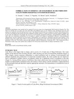
The model of the NRS used in this study is presented in figure 2.2 in
which the process and controller are communicated through a
communications network. The network causes the delay, out-oforder, and loss to the data exchanged in the system.
The networks used in NRSs vary in communications protocols and
topologies. For industrial and transport applications, it is convenient
to use fieldbuses (e.g. FIP and PROFIBUS) and automotive buses
(e.g. CAN). For service, education, and some others, it is more
appropriate to employ general purpose networks (e.g. IEEE LAN’s
and ATM-LAN) and the Internet. Nevertheless, those networks
introduce several common characteristics when being used for NRSs.
k+n
λkcau
Actuator
Process
k+n+1
Sensors
x
k+n+1 z
Network
(Delay, Loss, Out of Order)
k+n+m+1 λsck+n+1 z
k
u
Controller
Figure 2.2: Model of the networked robot system.
Let n be the network delay (in number of sampling periods) between
the controller and the actuator, m be the network delay between the
sensor and the controller, kca be the binary random variable described
the arrival of inputs from the controller to the actuator, ksc be the
binary random variable described the arrival of measurements from
ti tk ( j i )Ts
3
Network delay: Network delay is inevitable and is in general
time-varying. Its value can be measured by reading the
timestamp added to the sending message and then comparing it
with the receiving time. This method requires the internal clocks
of sender and receiver to be synchronized.
Out-of-order delivery: Messages delivered through different
routes may arrive in wrong order. An out-of-order message with
sequence number i arrived at time k (i k ) equivalents to a
delayed message with the time delay:
4
(2.10)
where tk is the transfer time at time k, j is the sequence number
of the last received chronologic message, and Ts is the sampling
period.
Message loss: Message loss is inevitable and can be defined as a
binary random variable k :
1, if a message arrives during time k 1to k
0, otherwise
k
(2.11)
Figure 2.5: The robot’s pose and parameters.
The kinematic model of the robot in the continuous and discrete time
domain is given by:
2.3 The robot
We have developed a real NRS to serve as a platform for study and
experiment. Figure 2. shows an overview of the system.
x vc cos
y vc sin
xk 1 xk Ts vc (k ) cos k
yk 1 yk Ts vc (k )sin k
(2.13)
(2.16)
k 1 k Tsc (k )
c
where vc is the tangent velocity, ωc is the angular velocity, and Ts is
the sampling period.
2.3.2 Hardware configuration
Figure 2.4: Overview of the developed NRS.
2.3.1 Kinematic model
The robot used in this study is the two wheeled, differential-drive
mobile robot. Its pose includes the position of the wheels axis center
(x, y) and the chassis orientation with respect to the X axis. Figure
2.5 shows the coordinate systems and notations for the robot where
(XG, YG) is the global coordinate, (XR, YR) is the local coordinate
related to the robot chassis, R denotes the radius of driven wheels,
and L denotes the distance between the wheels.
The hardware configuration contains two parts: actuators and sensors,
and user-interaction devices (figure 2.4). The actuators and sensors
include drive motors for motion control, sonar ranging sensors for
obstacle avoidance, compass and GPS sensors for heading and global
positioning, and laser range finder (LRF) and vision system for
mapping and navigation. The user-interaction devices include a
control computer and a joystick.
2.3.3 Data communications
The data communications is handled by a multi-protocol model. The
model utilizes different protocols for each type of the exchanged data
so that the overall performance is enhanced. The choice of protocols
5
6
is based on analysis of protocols in conjunction with the data
exchanged in a NRS.
Three main transport protocols including the TCP, UDP, and RTP are
analyzed. TCP is a sophisticated protocol which was originally
designed for the reliable transmission of static data such as e-mails
and files over low-bandwidth, high-error-rate networks. UDP is
based on the idea of sending a datagram from a device to another as
fast as possible without due consideration of the network state. RTP
is designed for the delivery of real-time multimedia data. Simulations
by ns-2 show that each protocol has its strengths and weaknesses so
that there is no single protocol can simultaneously adequate for
transmitting all types of data of the NRS.
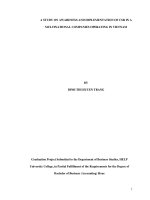
Figure 2.16 shows the implementation of the multi-protocol model.
Experimental results show that the multi-protocol model is adequate
for data communications between components of the NRS.
Data of the NRS can be classified into three groups: administrative
data, control signals, and vision data.
The administrative data contains the access control, user
validation, and configuration information. This type of data has
small packet size with the bandwidth lower than 10Kbps. In the
implementation, the TCP is adopted for the communications of
the administrative data.
The control signals include the control commands, synchronous
messages, and sensory measurements. This data consumes the
bandwidth from 1Kbps to 100Kbps and requires real-time
delivery. With those features, the UDP is utilized to deliver the
control signals.
The vision data is transmitted periodically with large packet size.
It consumes a lot of bandwidth and requires real-time delivery. In
our model, the RTP is employed for the transmission of the
vision data.
Figure 2.16: Data communications in the NRS using multi-protocol
model.
Chapter 3: Localization Using Optimal Filter
3.1 Robot localization
Localization, the estimation of robot’s location relative to the
environment, is the most fundamental problem to provide robots truly
autonomous capabilities. In order to complete a given task, the robot
needs to know where it is. Localization methods include the dead
reckoning, absolute positioning, and sensor fusion.
3.2 Localization of NRSs
In NRSs, the localization faces new challenges related to the
communications network. In this study, a new localization algorithm
based on the Kalman filter’s theory is proposed. This algorithm is
8
7
K k FPi H iT [ H i Pi H iT Ri ]1
able to deal with mixed uncertainties of random delay, message loss,
and out-of-order delivery.
3.3 Localization of NRSs using past-observation based extended
Kalman filter
The localization algorithm is derived through two steps. First, it is
developed for the linear system. It is then expanded to the nonlinear
system.
Pk Pk K k H i Pi F T
The time update equations at the prediction phase:
xˆ k f (xˆ k 1 , u k n 1 , 0)
Pk Ak 1 Pk1 AkT1 Wk 1Qk 1WkT1
(3.7)
m
F Ak j ( I K k j H k j )
ksc m H k m x k m ksc m v k m
H x v
i
j 1
(3.8)
T ) 1
K k FPi H iT ( H i Pi H iT Vi RV
i i
i
xˆ xˆ K [z h (xˆ , 0)]
i
k
(3.10)
The priori error covariance:
Pk Ak 1 Pk1 AkT1 Qk 1
(3.14)
The posteriori state estimate (correction phase):
xˆ k xˆ k K k (z ik H i xˆ i )
k
k
i
k
3.4 Simulation
The priori state estimate (prediction phase):
xˆ k Ak 1xˆ k 1 Bk 1u k n 1
k
(3.46)
P P K k H i Pi F T
k
Using the Kalman filter’s theory, a new optimal filter can be derived
as follows:
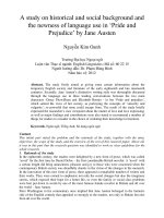
Figure 3.13 compares the localization result of three methods:
extended Kalman filter (EKF), improved extended Kalman filter
(LEKF) [28], and our filter (PO-EKF). Table 3.2 shows the amount
of floating point operations and the execution time of different filters,
scaled with respect to the EKF. It is concluded that the PO-EKF is
better accurate than the EKF, as accurate as the LEKF, and less
computational demanding than the LEKF.
(3.15)
The Kalman gain and posteriori error covariance:
10
9
(3.45)
The data update equations at the correction phase:
z ik ksc m z k m
i
(3.29)
Expanding the filter to the nonlinear system by linearizing it around
the previous estimates and then applying the above equations gives a
new filter called the PO-EKF as follows:
If the functions f and h in equation (2.4) are linear, the NRS can be
rewritten as:
x k Ak 1x k 1 kca n 1 Bk 1u k n 1 w k 1
Ak 1x k 1 Bk 1u k n 1 w k 1
(3.30)
0.1
0.2
EKF
PO-EKF
LEKF
0
Error in X (m)
RMSE in X (m)
0.15
0.1
0.05
-0.1
-0.2
-0.3
EKF
PO-EKF
LEKF
0
-0.4
0
200
400
600
Time (100ms)
800
1000
Parameter
Floating point
operations
Execution time
EKF
LEKF
PO-EKF
1.0
36.5
4.7
1.0
33.7
2.4
3.5 Experiment
Figure 3.24 presents the experimental result with the network
parameters measured as follows: the time delay is between 300ms
and 500ms; the out-of-order rate is 2.4%; and the loss rate is 1.3%.
The PO-EKF is more accurate than the EKF, as accurate as the
LEKF, and less computationally demanding than the LEKF. This
result is consistent with the theory and simulation results.
150
Chapter 4: Stable Control using Lyapunov Stability Theory
and Predictive Filter
4.1 Introduction
In non-networked robot system, a number of researches have been
proposed and the problem of stabilization control has been solved in
both theoretic and experimental aspects. In NRSs, several works have
been introduced to deal with the stabilization problem, but they
mainly focus on the time delay. In this study, we present our
approach with the use of the Lyapunov theory and predictive filter to
deal with mixed uncertainties of random delay, message loss, and
out-of-order data delivery.
4.2 Problem formulation
Consider the robot with kinematic model described in equation
(2.13). Let the difference between the present pose ( x, y, ) and the
11
50
100
Time (100ms)
Figure 3.24: Comparison between the EKF, LEKF, and PO-EKF.
Figure 3.15: Root mean square error of the EKF, LEKF, and POEKF in X direction.
Table 3.2: Normalized computational burden of the filters
0
12
v cos
goal pose ( x2 , y2 , 2 ) given in the robot reference frame { X R , YR , R }
be the error vector e ( x2 x, y2 y, 2 )T . The task of the
controller layout is to find a control constraint, if it exists, of the
tangent and angular velocities such that the error e is driven toward
zero: lim e(t ) 0 .
v
v
(4.2)
sin
t
According to the work of Brockett [78], Cartesian state-space
representations of the robot cannot be asymptotically stabilized via
smooth and time invariant feedback laws. A new coordinate system
is defined with three parameters (,,) called navigation variables
as shown in figure 4.2 and equation (4.1).
sin
The goal now is to establish smooth control laws that drive the
navigation variables (,,) toward zero. Our approach consists of
two steps. First, control laws that stabilize the non-networked robot
system are derived. A predictive filter is then introduced to extend
those control laws to the NRS.
4.3 Stabilization of Non-networked Robot System
Control laws to stabilize non-networked robot system are derived
based on [74]. Defining the Lyapunov function in the positive
definite quadratic form as follows:
V V1 V2
2
2
2
h 2
2
;
,h 0
(4.3)
We can prove that the derivation of the Lyapunov function V is
always negative if the control laws are chosen as follows:
Figure 4.2: The robot poses and navigation variables.
x2 x y2 y
atan 2 y2 y, x2 x 2
atan 2 y2 y, y2 x
2
v ( cos ) ; 0
2
(4.1)
Without lost of generality, we assume that the final desired pose of
the robot is ( x2 , y2 , 2 ) (0,0,0) which can also be expressed by
( 2 , 2 , 2 ) (0,0,0) . The kinematic equation (2.13) is then written in
the navigation variables domain (,,) as:
( h )
(4.8)
Discretizing above equations gives the stable control laws in discrete
time domain:
vk ( cos k ) k
wk k
13
cos sin
(4.5)
cos k sin k
k
14
( k hk )
(4.12)
4.4 Stabilization of NRS
4.5 Simulations and experiments
Consider the NRS described in equation (2.4). Due to the network,
the system is time-varying in which the control input at time k would
not reach the actuator until time k+n whereas the measurement at
time k actually reflects the system state at time k-m. Thus, in order to
ensure the stabilization of control laws (4.12), we need to predict the
system state at time k+n based on the measurements taken at time km, xˆ ( k n | k m) (figure 2.2).
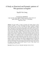
Figure 4.11 presents the trajectories and orientations of the robot in
three experiments in which the robot respectively starts from points
(-4,-4,00), (-4,-4,450), and (-4,-4,900) to reach the destination (0,0,00).
Figure 4.12 describe the tangent and angular velocities of the robot
during the operation. The robot goes toward the goal position while
the velocities go to zero. The system therefore is stable.
Orientation (degree)
Y (m)
-1
-2
The time update equations at prediction phase:
-3
xˆ k f k 1 (xˆ k 1 , u k 1 , 0)
-4
Pk Ak 1 Pk1 AkT1 Wk 1Qk 1WkT1
100
0
In chapter 3, the PO-EKF allows to estimate the present state from
past observations. If we add an extrapolated phase based on the time
update equation, the PO-EKF can be augmented to estimate
xˆ ( k n | k m) as follows:
(4.15)
0 degree
45 degree
90 degree
-4
-3
-2
X (m)
-1
60
40
20
0
0
(a)
0 degree
45 degree
90 degree
80
0
20
40
Time (s)
60
80
(b)
The data update equations at correction phase:
Figure 4.11: Stable control of the NRS with the use of the predictive filter:
(a) Trajectory of the robot in the motion plane; (b) Variation of the direction
of the robot.
m
F Ak j ( I K k j H k j )
j 1
T ) 1
K k FPi H iT ( H i Pi H iT Vi RV
i i
i
xˆ xˆ K [z h (xˆ , 0)]
k
k
k
k
(4.16)
i
P P K k H i Pi F T
k
k
The predictive equation at extrapolated phase:
xˆ k n f k n 1 (xˆ k n 1 , u k n 1 , 0)
(4.17)
15
16
0.4
behaviors that together result in the desired robot motion. The key
advantage of the behavior-based navigation is that it can adapts very
quickly to the change of the network and operating environments
without requiring the operator’s effort.
0.2
5.2 Behavior-based navigation for NRSs
0 degree
45 degree
90 degree
0.3
0.2
0.1
0
0
20
40
Time (s)
Angular velocity (rad/s)
Tangent velocity (m/s)
0.8
0
-0.2
60
0 degree
45 degree
90 degree
0.6
0
20
40
Time (s)
60
Figure 5.3 shows the architecture of the behavior-based navigation
for NRSs. It has three behaviors including the user following,
obstacle avoidance, and goal reaching, and one supervisory module.
(b)
(a)
Figure 4.12: Velocities of the robot during the stable control with the use of
the predictive filter: (a) Tangent velocity; (b) Angular velocity.
Chapter 5: Navigation Using Behavior-based Model
5.1 Introduction
The final goal of most mobile robot systems is the ability to
determine its own position in the environment and then drive towards
some goal locations to complete given tasks. This process is
navigation and typically contains 4 steps: perception, the robot
interprets its sensors to extract meaningful data; localization, the
robot determines its position in the environment; cognition, the robot
decides how to act to achieve its goals; and motion control, the robot
modulates its motor outputs to achieve the desired trajectory. There
are two main approaches in navigation including direct and behaviorbased navigations. In direct navigation, operators set the primitive
force or velocity commands to perform remote control.
Environmental information and robot states are transmitted in real
time for displaying on the operator’s monitor. Behavior-based
navigation, on the other hand, uses the concept of designing sets of
Figure 5.3: The architecture of our behavior-based navigation system.
The user following behavior translates high level commands of the
teleoperator to low level control signals so that the robot moves
accordantly with the teleoperator’s desire. This behavior also updates
the network state during the operation to tune control signals so that
the system is more adaptive. This behavior is implemented using
fuzzy logic with four steps characterized for fuzzy systems: defining
the problem, defining the linguistic variables and membership
functions, building the fuzzy rules, and defuzzification.
18
17
The obstacle avoidance behavior tends to avoid collisions with
obstacles that are in the vicinity of the robot. When appearing
obstacles, this behavior uses the ultrasonic data to avoid them. The
fuzzy logic is employed to implement this behavior including four
steps similarly to the user following behavior.
20
F
Obstacle 2
18
G
Goal
wall 4
16
E
Obstacle 4
14
The goal reaching behavior uses the control algorithm described in
chapter 4.
wall 3
12
Y(m)
D
Finally, the supervisory module determines the priority of behaviors
and decides the control signals the actuators shall receive. Inputs of
the supervision module include the network states (delay, loss, outof-order) and values of the three sonar sensors (front, left, right). Its
outputs are the rotational speeds of the left and right driven motors.
The operation of the supervision layer program is based on fuzzy
rules such as “If context Then behavior”.
wall 2
10
C
8
B
6
Obstacle 6
wall 1
2
0
Obstacle 5
Obstacle 1
4
Start
A
0
Obstacle 3
5
10
X(m)
15
20
Figure 5.14: Result of the behavior-based navigation.
5.3 Simulations and experiments
Simulations and experiments have been carried out to evaluate the
navigation model. Figure 5.14 present the navigation result in
unknown environment with many obstacles. The robot succeeded in
following user commands, avoiding obstacles and reaching the goal
position. The matching between control signal and network state
confirmed the functioning operation of the proposed navigation
model (figure 5.15-5.16).
2500
2000
B
Time delay (ms)
Delay
Loss
Out-of-order
E
C
D
G
A
F
1500
1000
500
0
0
200
400
600
800
1000 1200
Time (100ms)
1400
1600
1800
Figure 5.15: Network state during navigation.
20
19
2000
Angular velocity (rad/s)
25
L
B
20
R
E
10
A
F
D
5
0
C
15
0
200
400
600
800
1000 1200
Time (100ms)
G
1400
1600
1800
2000
Figure 5.16: Angular velocities of the left and right wheels during
navigation.
Chapter 6: Conclusion
This study proposed algorithms for fundamental problems of NRS
including the localization, stabilization control, and navigation. The
development of algorithms was carried out through steps of
analyzing the applicability, evaluating the related research,
formulating the system model, proposing the algorithms, and finally
evaluating the performance through simulations and experiments.
The main contributions of this study are as follows:
Development of a unified state-space representation of the
NRS under the influence of network delay, message loss, and
out-of-order delivery. This representation has been adopted to
solve fundamental problems of NRSs. A real NRS was
developed as the platform for experiments and evaluations. A
multi-protocol model was proposed for the data communications
between components of the NRS. The model utilizes advantages
of individual transport protocols in delivering certain types of the
22
21
communications data to enhance the communications
performance. These results were published in [1][2][3][4][5][10].
A new optimal filter namely the PO-EKF was proposed for
the problem of state estimation and localization of NRSs. The
filter can deal with the mixed uncertainties of network delay,
message loss, and out-of-order delivery. The optimality of the
filter in term of minimizing the mean square error was
theoretically proven. The expansion of the filter to non-linear
NRSs was derived. A number of simulations, comparisons, and
experiments were conducted. The results confirmed the accuracy,
computational efficiency, and implemental capability of the
filter. These results were published in [12][13].
A control algorithm to stabilize the NRS was proposed. It
basically based on the approach in [31], but a new predictive
filter was introduced to improve the accuracy and extend the
functionality of the controller to deal with not only the network
induced delay but also the message loss and out-of-order. These
results were published in [8][9].
Development of a behavior-based navigation model to
navigate the networked robot in unknown environments. Fuzzy
logic was employed to increase the adaptation of system to the
network. Simulations and experiments in various environments
proved the efficiency of the proposed model. These results were
published in [6][7][11].
List of Publications
1.
Trần Quang Vinh, Phùng Mạnh Dương, Trần Hiếu (2005), “Giám sát và
điều khiển robot di động qua mạng LAN vô tuyến và Internet”, Tạp chí
khoa học Tự nhiên và Công nghệ, Đại học Quốc gia Hà Nội, Tập 21, số
2, tr.85-91.
2. Trần Quang Vinh, Vũ Tuấn Anh, Phùng Mạnh Dương, Trần Hiếu
(2006), “Xây dựng robot di động được dẫn đường bằng các cảm biến
siêu âm và cảm biến ảnh toàn phương”, Hội nghị Cơ điện tử toàn quốc
lần thứ 3 (VCM), tr.153-160.
3. Manh Duong Phung, Quang Vinh Tran, Kok Kiong Tan (2010),
“Transport Protocols for Internet-based Real-time Systems: A
Comparative Analysis,” The Third International Conference on
Communication and Electronics (ICCE).
4. Phùng Mạnh Dương, Quách Công Hoàng, Vũ Xuân Quang, Trần
Quang Vinh (2010), “Điều khiển robot di động qua mạng Internet sử
dụng kiến trúc truyền thông CORBA”, The International Conference on
Engineering Mechanics and Automation (ICEMA), pp.232-237.
5. Trần Quang Vinh, Phạm Mạnh Thắng, Phùng Mạnh Dương (2010),
“Mạng thông tin điều khiển trong hệ thống tự động hóa tòa nhà”, Tạp
chí Khoa học Tự nhiên và Công nghệ, Đại học Quốc gia Hà Nội, Tập
26, số 2, tr.129-140.
6. Manh Duong Phung, Thanh Van Thi Nguyen, Cong Hoang Quach,
Quang Vinh Tran (2010), “Development of a Tele-guidance System
with Fuzzy-based Secondary Controller”, The 11th IEEE International
Conference on Control, Automation, Robotics and Vision (ICARCV),
pp.1826-1830.
7. Manh Duong Phung, Thanh Van Thi Nguyen, Tran Quang Vinh (2011),
“Control of an Internet-based Robot System Using Fuzzy Logic”, The
2011 IEICE International Conference on Integrated Circuits and
Devices in Vietnam (ICDV), pp.98-101.
8. Phùng Mạnh Dương, Nguyễn Thị Thanh Vân, Trần Thuận Hoàng, Trần
Quang Vinh (2012), “Điểu khiển ổn định robot di động phân tán qua
mạng máy tính sự dụng bộ lọc dự đoán với quan sát quá khứ”, Hội nghị
Cơ điện tử Toàn quốc lần thứ 6 (VCM), tr.778-786.
9. T. H. Hoang, P. M. Duong, N. V. Tinh, T. Q. Vinh (2012), “A Path
Following Algorithm for Wheeled Mobile Robot Using Extended
Kalman Filter”, The 3rd IEICE International Conference on Integrated
Circuits and Devices in Vietnam (ICDV), pp.179-183.
10. Manh Duong Phung, Thuan Hoang Tran, Thanh Van Thi Nguyen and
Quang Vinh Tran (2012), “Control of Internet-based Robot Systems
Using Multi Transport Protocols”, 2012 IEEE International Conference
on Control, Automation and Information Sciences (ICCAIS), pp.294299.
11. P. M. Duong, T. T. Hoang, N. T. T. Van, D. A. Viet and T. Q. Vinh
(2012), “A Novel Platform for Internet-based Mobile Robot Systems”,
The 7th IEEE Conference on Industrial Electronics and Applications
(ICIEA), pp.1969-1974.
12. Manh Duong Phung, Thi Thanh Van Nguyen, Thuan Hoang Tran, and
Quang Vinh Tran (2013), “Localization of Networked Robot Systems
Subject to Random Delay and Packet Loss”, The 2013 IEEE/ASME
International Conference on Advanced Intelligent Mechatronics (AIM),
pp.1442-1447.
13. Manh Duong Phung, Thi Thanh Van Nguyen, Thuan Hoang Tran,
Quang Vinh Tran (2013), “Localization of Internet-based Mobile
Robot”, Tạp chí Khoa học Tự nhiên và Công nghệ, Đại học Quốc gia
Hà Nội, Tập 29, số 1, tr. 1-13.
23
24