giáo trình nền móng của đại học xây dựng bản tiếng anh
Bạn đang xem bản rút gọn của tài liệu. Xem và tải ngay bản đầy đủ của tài liệu tại đây (4.21 MB, 90 trang )
NATIONAL UNIVERSITY OF CIVIL ENGINEERING
DIVISION OF SOIL MECHANICS AND FOUNDATION ENGINEERING
FOUNDATION ENGINEERING
(FOR THE ENGLISH COURSE)
NGUYEN BAO VIET
LE THIET TRUNG
HA NOI - 2013
National University of Civil Engineering
i
CONTENTS
CONTENTS .....................................................................................................................i
LIST OF FIGURES ....................................................................................................... iii
PREFACE ........................................................................................................................v
CHAPTER 1:
INTRODUCTION ................................................................................1
CHAPTER 2:
SHALLOW FOUNDATIONS ............................................................. 3
2.1
Introduction ..................................................................................................3
2.2
Main Components of Shallow Foundations ................................................5
2.3
Contact Pressure Distribution beneath Base of Footing .............................. 7
2.3.1 Contact Pressure Distribution of Spread Footing ........................................9
2.3.2 Contact Pressure Distribution of Wall Footing .........................................10
2.3.3 Net Load Applied on Footing Base ........................................................... 10
2.3.4 Vertical Stress Increase ..............................................................................10
2.4
Ultimate Bearing Capacity of Shallow Foundation ...................................12
2.4.1 General .......................................................................................................12
2.4.2 Terzaghi‘s Bearing Capacity Theory .........................................................13
2.4.3 The General Bearing Capacity Equation ...................................................17
2.4.4 General Bearing Capacity Equation in Practice ........................................19
2.4.5 Safety Factor and Allowable Load-Bearing Capacity ............................... 20
2.4.6 Bearing Capacity of Layered Soils: Stronger Soil underlain by Weaker
Soil .............................................................................................................20
2.5
Shallow Foundation Design .......................................................................21
2.5.1 Introduction ................................................................................................ 21
2.5.2 Design Procedure for Shallow Foundation. ...............................................21
2.5.3 Geotechnical Analyses and Design............................................................ 22
2.5.4 Structural Footing Design ..........................................................................25
CHAPTER 3:
SOIL IMPROVEMENT .....................................................................30
3.1
Sand Replacement ......................................................................................31
3.2
Sand Compaction Piles ..............................................................................32
3.2.1 Characteristics of Sand Compaction Piles .................................................34
3.2.2 Sand Compaction Pile Working Procedure ...............................................35
3.2.3 Applied Assumptions in Calculation of Sand Compaction Piles ..............36
Foundation Engineering
CONTENTS
National University of Civil Engineering
ii
3.2.4 Principle of Sand Compaction Pile Analyses ............................................36
3.2.5 Plan layout and Distance of Sand Compaction Pile ..................................37
3.2.6 Estimation of Improved Soil Properties ....................................................41
3.3
Vibroflotation ............................................................................................. 42
3.4
Blasting ......................................................................................................44
3.5
Precompression .......................................................................................... 44
3.6
Stone Columns ........................................................................................... 45
3.7
Dynamic Compaction ................................................................................46
3.8
Jet Grouting ................................................................................................ 48
3.9
Recommendation of Improvement Methods for Soils............................... 49
CHAPTER 4:
4.1
PILE FOUNDATIONS ......................................................................50
Definitions and classifications ...................................................................50
4.1.1 Definitions..................................................................................................50
4.1.2 Classifications of piles ...............................................................................52
4.1.3 Advantages and disadvantages of different pile material .......................... 58
4.2
Constitution of a Prefabricated Reinforced Concrete Pile .........................62
4.3
Bearing Capacity of a Single Pile .............................................................. 66
4.3.1 Definitions..................................................................................................66
4.3.2 Pile axial bearing capacity. ........................................................................66
4.4
Design of Low Pile Cap Foundation .........................................................74
4.4.1 Design hypotheses .....................................................................................74
4.4.2 Material selection for pile and pile cap ......................................................74
4.4.3 Pile dimension selection and pile load capacity calculation ......................75
4.4.4 Pile quantity and pile arrangement ............................................................ 75
4.4.5 Verification of load applied to pile ............................................................ 76
4.4.6 Verification of the resistance of bearing stratum .......................................77
4.4.7 Calculation of pile foundation settlement ..................................................78
4.4.8 Pile cap height ............................................................................................ 78
4.4.9 Verification of pile when transportation and positioning .......................... 81
4.4.10 Selection of hammer for driven piles .........................................................82
REFERENCES ..............................................................................................................83
Foundation Engineering
CONTENTS
National University of Civil Engineering
iii
LIST OF FIGURES
Figure 2-1 (a) Strip foundation under a wall (b) Strip foundation under columns
(c) Spread foundation (d) Mat foundation. (1) Footing (2) Wall (3)
Column ...................................................................................................... 3
Figure 2-2 Examples of spread foundations .................................................................... 3
Figure 2-3 Examples of shallow foundations (a) Combined footing; (b) combined
trapezoidal footing; (c) cantilever or strap footing; (d) octagonal
footing; (e) eccentric loaded footing with resultant coincident with
area so soil pressure is uniform. ................................................................ 4
Figure 2-4 Examples of mat foundations (a) Flat plate; (b) plate thickened under
columns; (c) beam-and-slab; (d) plate with pedestals; (e) basement
walls as part of mat. ................................................................................... 4
Figure 2-5 A typical cross section of spread footing....................................................... 5
Figure 2-6 Reinforcement of a spread footing ................................................................ 6
Figure 2-7 Behavior of foundations with connecting beams .......................................... 6
Figure 2-8 Ground beam and footing reinforcements ..................................................... 7
Figure 2-9 Settlement profile and contact pressure in sand: (a) flexible
foundation; (b) rigid foundation ............................................................. 8
Figure 2-10: Settlement profile and contact pressure in clay: (a) flexible
foundation; (b) rigid foundation ................................................................ 8
Figure 2-11: Linear distribution of contact pressure ....................................................... 9
Figure 2-12 2:1 method of finding stress increase under a foundation ......................... 11
Figure 2-13 Nature of bearing capacity failure in soil: (a) general shear failure:
(b) local shear failure; (c) punching shear failure. .................................. 12
Figure 2-14 Bearing capacity failure in soil under a rough rigid continuous (strip)
foundation ................................................................................................ 14
Figure 2-15 Bearing capacity of a strip foundation on layered soil ............................. 20
Figure 2-16 Two-way shear calculation ........................................................................ 26
Figure 2-17 Wide-beam shear calculation ..................................................................... 27
Figure 2-18 Flexure reinforcement calculation ............................................................. 28
Figure 3-1 (a) Completed sand replacement (b) Partial sand replacement ................... 31
Figure 3-2 Sand compaction pile test of Basore and Boitano (1969): (a) Layout of
the compaction piles; (b) Standard penetration resistance variation
with depth and S’ ..................................................................................... 33
Figure 3-3 Sand compaction pile mandrel tip ............................................................... 34
Figure 3-4 Characteristic of sand compaction piles for a spread footing ...................... 35
Figure 3-5 Sand compaction pile working procedure ................................................... 36
Figure 3-6 Principle of sand compaction pile analyses ................................................. 37
Figure 3-7 Compaction area for (a) strip footing and (b) spread footing ...................... 38
Figure 3-8 Plan layout of sand compaction piles (a) equiangular triangle (b)
Square ...................................................................................................... 40
Foundation Engineering
LIST OF FIGURES
National University of Civil Engineering
iv
Figure 3-9 Vibroflotation unit ....................................................................................... 42
Figure 3-10 Compaction by the vibroflotation process ................................................. 43
Figure 3-11 Principles of precompression ..................................................................... 44
Figure 3-12 Sand drain .................................................................................................. 45
Figure 3-13 Prefabricated vertical drain (PVD) ............................................................ 45
Figure 3-14 (a) Stone columns in a triangular pattern; (b) stress concentration due
to change in stiffness ............................................................................... 46
Figure 3-15 Rig of Dynamic compaction ...................................................................... 47
Figure 3-16 Dynamic compaction, working procedure ................................................. 47
Figure 3-17 Effects of soil Improvement by Dynamic compaction &
Vibroflotation .......................................................................................... 48
Figure 3-18 Jet grouting ................................................................................................ 49
Figure 3-19 Site improvement methods as a function of soil grain size ....................... 49
Figure 4-1: Low pile cap foundation – High pile cap foundation ................................. 52
Figure 4-2: Steel pile cross section ................................................................................ 53
Figure 4-3: End bearing pile .......................................................................................... 54
Figure 4-4: Friction or Cohesion pile ............................................................................ 54
Figure 4-5: under-reamed base enlargement to a bore-and-cast-in-situ pile ................. 55
Figure 4-6: Concrete driven piles system ...................................................................... 56
Figure 4-7: Drilling auger types: short section – single flight – double flight .............. 57
Figure 4-8: Bored pile phasing: Site preparation – Positioning – Excavation –
Rebar installation – Conrete pouring – Pile completion. ........................ 58
Figure 4-9: Different cross section of piles ................................................................... 63
Figure 4-10: Detailed design of prefabricated reinforced concrete pile ........................ 63
Figure 4-11: Cross section of a square pile ................................................................... 64
Figure 4-12: Stirrup bar: separate bar and spriral bar ................................................... 64
Figure 4-13: Details of pile toe ...................................................................................... 64
Figure 4-14: Steel grid at pile top – Hook rebar............................................................ 64
Figure 4-15: Steel plate at the pile top........................................................................... 65
Figure 4-16: Details of pile connection ......................................................................... 65
Figure 4-17: s c kháng bên qci và s c kháng m i qcn trong thí nghi m CPT ............... 68
Figure 4-18 Typical static load test arrangement showing instrumentation ................. 70
Figure 4-19: Two P-S curves types (a, b) and T-S curve (c)......................................... 71
Figure 4-20: Piles arrangement in side view. ................................................................ 75
Figure 4-21: Piles arrangement in plan view ................................................................. 76
Figure 4-22: Equivalent raft .......................................................................................... 77
Figure 4-23: damage pile cap by column ...................................................................... 79
Figure 4-24: damage of pile cap by pile reaction .......................................................... 80
Figure 4-25: Rebar area calculation schemas ................................................................ 81
Figure 4-26: Pile transportation verification ................................................................. 81
Figure 4-27: Pile positioning verification...................................................................... 82
Foundation Engineering
LIST OF FIGURES
National University of Civil Engineering
v
PREFACE
Soil mechanics and foundation engineering have developed rapidly during the last
fifty years. Intensive research and observation in the field and the laboratory have
refined and improved the science of foundation design.
This text book of ―Foundation Engineering‖ is edited for undergraduate civil
engineering students, who have passed the soil mechanics course, which is a
prerequisite for the foundation engineering course. The text is composed of four
chapters with examples and problems, and an answer section for selected problems.
The chapters are mostly devoted to the geotechnical aspects of foundation design and
briefly described as follows
Chapter 1 of introduction gives an overview of foundation engineering
Chapter 2 presents on the concept of shallow foundation and focus analyses and
design of spread footing and wall trip footing on several types of sub-soils. The
structural design of footing according to the Vietnamese codes also mentioned in detail
in this chapter.
Chapter 3 introduces various types of soil improvement in that sand cushion and
sand compaction piles are concentrated in analyses and design also.
Chapter 4 is dedicated for deep foundation of prefabricated piles. The estimation
of geotechnical and in structural bearing capacity of piles is mentioned based on both
theories and practices. Structural pile-cap design is an important content in this
chapter.
After this course, the students can get the basic knowledge in foundation
engineering. They could calculate and design foundation in some simple cases. This is
the first step for an engineer in geotechnical and foundation engineering.
Thanks are due to all members of Geotechnical and Foundation Engineering
Division of National University of Civil Engineering for their help and
encouragements during the preparation of this text.
I am also grateful for several helpful suggestions of Prof. Vu Cong Ngu and
Assoc. Prof. Pham Quang Hung.
The Authors
Dr. Nguyen Bao Viet
Dr. Le Thiet Trung
Foundation Engineering
PREFACE
National University of Civil Engineering
CHAPTER 1:
1
INTRODUCTION
All structures resting on the earth must be carried by an interface element called
foundation. A foundation is the lowest part of a structure that transmits to, and into, the
underlying soil or rock all loads of the super-structure and also its self-weight.
The term super-structure is commonly used to describe the engineered part of the
system bringing loads to the foundation, or substructure especially for buildings and
bridges. However, foundations also may carry only machinery, support industrial
equipment (pipes, towers, and tanks) act as sign base, and the like. Therefore it is
better to describe a foundation as a part of the engineered system that interfaces the
load-carrying component to the ground.
It is evident that a foundation is the most important part of the structures or
engineering system.
The design of foundations of structures such as buildings, bridges, and dams
generally requires knowledge of such factors as:
(a) The load that will be transmitted by the superstructure to the foundation
system,
(b) The requirements of the local building code,
(c) The behavior and stress-related deformability of soils that will support the
foundation system, and
(d) The geological conditions of the soil under consideration.
To a foundation engineer, the last two factors are extremely important because
they concern soil mechanics.
The geotechnical properties of a soil such as its grain-size distribution, plasticity,
compressibility, and shear strength can be assessed by proper laboratory testing. In
addition, recently emphasis has been placed on the in situ determination of strength
and deformation properties of soil, because this process avoids disturbing samples
during field exploration.
However, under certain circumstances, not all of the needed parameters can be or
are determined, because of economic or other reasons. In such cases, the engineer must
make certain assumptions regarding the properties of the soil. To assess the accuracy
of soil parameters whether they were determined in the laboratory and the field or
whether they were assumed the engineer must have a good grasp of the basic
principles of soil mechanics. At the same time, he or she must realize that the natural
soil deposits on which foundations are constructed are not homogeneous in most cases.
Thus, the engineer must have a thorough understanding of the geology of the area that
is, the origin and nature of soil stratification and also the groundwater conditions.
Foundation engineering is a clever combination of soil mechanics, engineering
geology, and proper judgment derived from past experience. To a certain extent, it
may be called an art. When determining which foundation is the most economical, the
engineer must consider the superstructure load, the subsoil conditions, and the desired
tolerable settlement.
Foundation Engineering
INTRODUCTION
National University of Civil Engineering
2
In general, foundations of the structures may be divided into two major categories:
(1) Shallow foundations.
(2) Deep foundations.
Spread footings, wall footings, and mat foundations are all shallow foundations. In
most shallow foundations, the depth of embedment can be equal to or less than three to
four times the width of the foundation. Pile and drilled shaft foundations are deep
foundations. They are used when top layers have poor load-bearing capacity and when
the use of shallow foundations will cause considerable structural damage or instability.
The separation is not strict but in the point of view of a foundation engineer, in
analysis and design of a shallow foundation, vertical friction between the foundation
and soils is neglected.
Foundation Engineering
INTRODUCTION
National University of Civil Engineering
CHAPTER 2:
3
SHALLOW FOUNDATIONS
2.1 Introduction
Shallow foundations, often called footings, are usually embedded about a meter or
so into soil. One common type is the spread footing which consists of strips or pads of
structural materials which transfer the loads from walls and columns to the soil or
bedrock.
Another common type of shallow foundation is the slab-on-grade foundation
where the weight of the building is transferred to the soil through a concrete slab
placed at the surface. Slab-on-grade foundations can be reinforced mat slabs, which
range from 25 cm to several meters thick, depending on the size of the building.
Concrete is almost universally used for footings because of its durability in a
potential hostile environment and for economy.
Figure 2-1 shows some shallow foundations including strip footings (a) and (b);
spread footing (c); and mat foundation (d). Furthermore, in Figure 2-2 there are several
common types of spread footing consist of constant footing (a); stepped footing (b);
and sloped footing (c).
Figure 2-1 (a) Strip foundation under a wall (b) Strip foundation under columns (c)
Spread foundation (d) Mat foundation. (1) Footing (2) Wall (3) Column
Figure 2-2 Examples of spread foundations
Various types of shallow foundation which could be used in practice such as combined
or connected footings and mat foundations are illustrated in Figure 2-3 and Figure 2-4.
Foundation Engineering
SHALLOW FOUNDATIONS
National University of Civil Engineering
4
Figure 2-3 Examples of shallow foundations (a) Combined footing; (b) combined
trapezoidal footing; (c) cantilever or strap footing; (d) octagonal footing; (e) eccentric
loaded footing with resultant coincident with area so soil pressure is uniform.
Figure 2-4 Examples of mat foundations (a) Flat plate; (b) plate thickened under
columns; (c) beam-and-slab; (d) plate with pedestals; (e) basement walls as part of
mat.
Foundation Engineering
SHALLOW FOUNDATIONS
National University of Civil Engineering
5
2.2 Main Components of Shallow Foundations
A shallow foundation basically consists of the following components:
- Leveling concrete
- Footings (single, strip, and mat)
- Ground beams
- Vertical supported structures such as columns, walls.
Figure 2-5 show a typical reinforced concrete footing. The concrete used for
foundation should not be less than B20 and reinforcement should not be less than 10.
Just based on soil, leveling concrete is the lowest layer with at least 100mm thick.
Leveling concrete creates a clean flat platform so that concrete work for the
foundations could be carried out fluently. The concrete used for leveling normally is
B7.5 with course aggregate of 4x6 rock.
Footings would be flat, step or slope as shown in Figure 2-2 with the minimum
thickness would be required as 150mm but 200mm is preferred in practice. Footing
reinforcements shown in Figure 2-5 to resist tensile stress induced in the footing. For
spread and wall strip footing, basically upper (top) reinforcement, hairpin and chair bar
are not necessary.
A rebar spacer is a device that secures the reinforcing steel is assembled in place
prior to the final concrete pour so that cover depth normally of 50mm is assured. The
spacers are left in place for the pour to keep the reinforcing in place, and become a
permanent part of the structure. Rebar spacer would be made of concrete or plastic.
Figure 2-5 A typical cross section of spread footing
Figure 2-6 illustrates rebar placement for a spread footing and supported column.
It should be noted that in case of stepped or sloped footing, footing‘s neck would be
required. The neck should be normally enlarged about 50mm for every directions of
the column. Sometimes column rebars need a hook so that they could stand on the
lower (bottom) reinforcements layer.
Foundation Engineering
SHALLOW FOUNDATIONS
National University of Civil Engineering
6
Figure 2-6 Reinforcement of a spread footing
Figure 2-7 Behavior of foundations with connecting beams
Foundation Engineering
SHALLOW FOUNDATIONS
National University of Civil Engineering
7
Figure 2-8 Ground beam and footing reinforcements
Generally, it is useful to place connecting beams at the foundation because they
carry the horizontal shear forces and prevent damage from differential settlements.
Connecting beam is also called ground beam because of the location the beams placed.
Figure 2-7 shows the behavior of spread footings tied together with ground beams.
Reinforcement for ground beam and footings are shown in Figure 2-8.
2.3 Contact Pressure Distribution beneath Base of Footing
The stress distribution under even symmetrically loaded footing is not uniform
following researches of Schultze (1961), Barden (1962) and Borowicka (1963). The
actual stress distribution depends on both footing rigidity and subsoil. For footing on
loose sand the grains near to edge tend to displace laterally, whereas interior soil is
relatively confined. Figure 2-9 shows the general diagram of the stress distribution for
both flexible and rigid shallow foundation on granular soil.
The theoretical pressure distribution for the general case of rigid footing on
cohesive soils is shown on Figure 2-10(b). The high edge pressure may be explained
by considering that edge shear must occur before any settlement can take place. Since
soil has low rupture strength, and most of footings are of intermediate rigidity, it is
very not likely that high edge shear stresses are developed.
The pressure distribution beneath most footings will be rather indeterminate
because of the interaction of the footing rigidity with the soil type, state, and time
response to stress. For this reason it is common practice to use linear pressure
distribution of Figure 2-11 beneath foundations whose rigidity are large enough such
as spread footings and strip footings under wall. Some of field measurements reported
indicated this assumption is adequate.
Foundation Engineering
SHALLOW FOUNDATIONS
National University of Civil Engineering
8
Figure 2-9 Settlement profile and contact pressure in sand: (a) flexible foundation;
(b) rigid foundation
Figure 2-10: Settlement profile and contact pressure in clay: (a) flexible foundation;
(b) rigid foundation
Foundation Engineering
SHALLOW FOUNDATIONS
National University of Civil Engineering
9
N
N
hm
Y
pmin
X
pmax
pmax
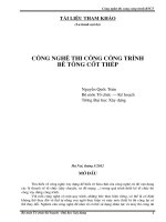
Figure 2-11: Linear distribution of contact pressure
2.3.1 Contact Pressure Distribution of Spread Footing
A footing carrying a single column is called spread footing, since its function is to
―spread‖ the column load laterally to the soil so that the stress intensity is reduced to a
value that soil can safely carry. These members sometimes called single or isolated
footings. Since the footings are subjected to moments in addition to vertical load, as
shown in Figure 2-11, distribution of the contact pressure by the foundation on soil is
not uniform. The nominal distribution of the pressure is:
Eq. 2-1
Eq. 2-2
Eq. 2-3
Where:
N is vertical axial force at footing level;
N0 is vertical axial force at the ground level;
, weight of footing and soil above footing
Foundation Engineering
SHALLOW FOUNDATIONS
National University of Civil Engineering
10
=20kN/m3 (approximate), average unit weight of footing material
(concrete) and soil above footing.
Mx, My are moments at footing level;
l, b are dimensions of spread footing.
2.3.2 Contact Pressure Distribution of Wall Footing
Wall footings serve a similar purpose of spreading the wall load to the soil.
Because of their long shape (ratio of length (l) to width (b) greater than 7), the footings
theoretically are considered as one-way structure. In reality, when the wall is high
enough so its internal resistance moment of the long axis is large then the bending of
the wall and also the footing could be ignored.
The distribution of the contact pressure is:
Eq. 2-4
Eq. 2-5
Eq. 2-6
Where:
N is vertical axial force distributed for 1m long at footing level;
N0 is vertical axial force distributed for 1m long at the ground level;
, weight of footing and soil above footing for 1m long;
M is moments distributed for 1m at footing level;
b is width of footing wall.
2.3.3 Net Load Applied on Footing Base
The net load applied on footing base is determined as the total stress at the footing
base level extract the geostatic (over-burden) stress at the base level.
Eq. 2-7
Where
’tb = effective unit weight of soils above footing base level.
2.3.4 Vertical Stress Increase
2.3.4.1 Method based on Boussineq Equation.
One of the most common methods to estimate stress increase at a depth under a
foundation from the net applied load ( p) is Boussineq Equation based on Theory of
Elasticity which have been mentioned at chapter 4 of the Soil mechanics text book. To
obtain the result, the load is assumed act on a homogenous, isotropic, weightless, and
elastic half-space of soil.
Foundation Engineering
SHALLOW FOUNDATIONS
National University of Civil Engineering
11
Certainty the increase stress, , is varies from point to point in the soil space but
in the engineering point of view, in conservative side, at each level should be
considered at the center of the foundation where it gets maximum value. To deal this
problem, an equivalent uniform distribution of load of p should be used as net
applied load. General equation based on chapter 4 of soil mechanics text book to get
the increase stress is
Eq. 2-8
Where k = loading factor depending on the shape of foundation base and the
depth of considered point.
2.3.4.2 Simple Equivalent Method (2:1Method).
p
Figure 2-12 2:1 method of finding stress increase under a foundation
Foundation engineers often use an approximate method to determine the increase
in stress with depth caused by the construction of a foundation. The method is referred
to as the 2:1 method (See Figure 2-12). According to this method, the increase in stress
at depth z is
for spread footing
Eq. 2-9
for strip footing
Eq. 2-10
Eq. 2-9 and Eq. 2-10 are based on the assumption that the stress from the
foundation spreads out along lines with a vertical-to-horizontal slope of 2:1.
Some authors have proposed the slope angle be anywhere from 30o to 45o. In
Vietnam, 30o is default for that angle. It should be noted that 2:1 method is widely
used over the world because of simplicity and conservative result.
Foundation Engineering
SHALLOW FOUNDATIONS
National University of Civil Engineering
12
2.4 Ultimate Bearing Capacity of Shallow Foundation
2.4.1 General
To perform satisfactorily, shallow foundations must have two main characteristics:
1. They have to be safe against overall shear failure in the soil that supports
them.
2. They cannot undergo excessive displacement, or settlement. (The term
excessive is relative, because the degree of settlement allowed for a
structure depends on several considerations.)
The load per unit area of the foundation at which shear failure in soil occurs is
called the ultimate bearing capacity, which is the subject of this part.
p
pgh
p
pgh(1)
pgh
p
pgh(1)
pgh pgh
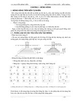
Figure 2-13 Nature of bearing capacity failure in soil: (a) general shear failure: (b)
local shear failure; (c) punching shear failure.
Foundation Engineering
SHALLOW FOUNDATIONS
National University of Civil Engineering
13
Consider a strip foundation with a width of b resting on the surface of a dense sand
or stiff cohesive soil, as shown in Figure 2-13(a). Now, if a load is gradually applied to
the foundation, settlement will increase. The variation of the load per unit area on the
foundation p with the foundation settlement is also Figure 2-13 failure in the soil
supporting the foundation will take place, and the failure surface in the soil will extend
to the ground surface. This load per unit area is usually referred to as the ultimate
bearing capacity of the foundation. When such sudden failure in soil takes place, it is
called general shear failure.
If the foundation under consideration rests on sand or clayey soil of medium
compaction Figure 2-13 (b), an increase in the load on the foundation will also be
accompanied by an increase in settlement. However, in this case the failure surface in
the soil will gradually extend outward from the foundation, as shown by the solid lines
in Figure 2-13 (b). When the load per unit area on the foundation equals movement of
the foundation will be accompanied by sudden jerks. A considerable movement of the
foundation is then required for the failure surface in soil to extend to the ground
surface (as shown by the broken lines in the figure). The load per unit area at which
this happens is the ultimate bearing capacity, pgh. Beyond that point, an increase in
load will be accompanied by a large increase in foundation settlement. The load per
unit area of the foundation, pgh(1), is referred to as the first failure load (Vesic, 1963).
Note that a peak value of p is not realized in this type of failure, which is called the
local shear failure in soil.
If the foundation is supported by a fairly loose soil, the load–settlement plot will
be like the one in Figure 2-13 (c). In this case, the failure surface in soil will not extend
to the ground surface. Beyond the ultimate failure load, pgh, the load–settlement plot
will be steep and practically linear. This type of failure in soil is called the punching
shear failure.
2.4.2 Terzaghi’s Bearing Capacity Theory
Terzaghi (1943) was the first to present a comprehensive theory for the evaluation
of the ultimate bearing capacity of rough shallow foundations. According to this
theory, a foundation is shallow if its depth, (Figure 2-14), is less than or equal to its
width. Later investigators, however, have suggested that foundations with equal to 3 to
4 times their width may be defined as shallow foundations.
Terzaghi suggested that for a continuous or strip foundation (i.e., one whose width
to length ratio approaches zero), the failure surface in soil at ultimate load may be
assumed to be similar to that shown in Figure 2-14. (Note that this is the case of
general shear failure, as defined in Figure 2-14a.) The effect of soil above the bottom
of the foundation may also be assumed to be replaced by an equivalent surcharge,
(where is a unit weight of soil). The failure zone under the foundation can be separated
into three parts (see Figure 2-14):
Foundation Engineering
SHALLOW FOUNDATIONS
National University of Civil Engineering
14
1. The triangular zone ACD immediately under the foundation
2. The radial shear zones ADF and CDE, with the curves DE and DF being arcs
of a logarithmic spiral
3. Two triangular Rankine passive zones AFH and CEG
hm
q = .hm
Figure 2-14 Bearing capacity failure in soil under a rough rigid continuous (strip)
foundation
The angles CAD and ACD are assumed to be equal to the soil friction angle ’.
Note that, with the replacement of the soil above the bottom of the foundation by an
equivalent surcharge q, the shear resistance of the soil along the failure surfaces GI
and HJ was neglected.
Using equilibrium analysis, Terzaghi expressed the ultimate bearing capacity in
the form
Eq. 2-11
c’ = cohesion of soil
= unit weight of soil
q = hm
N , Nq, Nc = bearing capacity factors that are non-dimensional and
are functions only of the soil friction angle, ’.
The bearing capacity factors N , Nq, Nc are defined by
Where:
Eq. 2-12
Eq. 2-13
Foundation Engineering
SHALLOW FOUNDATIONS
National University of Civil Engineering
15
Eq. 2-14
Where
Kp = passive pressure coefficient.
The variations of the bearing capacity factors defined by Eq. 2-12, Eq. 2-13, and
Eq. 2-14 are given in Table 2-1
Table 2-1 Terzaghi‘s Bearing Capacity Factors
To estimate the ultimate bearing capacity of square and circular foundations, Eq.
2-11 may be respectively modified to
for square foundation
Eq. 2-15
for circular foundation
Eq. 2-16
In Eq. 2-15, b equals the dimension of each side of the foundation; in Eq. 2-16, b
equals the diameter of the foundation.
For foundations that exhibit the local shear failure mode in soils, Terzaghi
suggested the following modifications to Eq. 2-11, Eq. 2-15, and Eq. 2-16:
Foundation Engineering
SHALLOW FOUNDATIONS
National University of Civil Engineering
16
for strip foundation
Eq. 2-17
for square foundation
Eq. 2-18
for circular foundation
Eq. 2-19
N’ , N’q, and N’c, the modified bearing capacity factors, can be calculated by
using the bearing capacity factor equations (for N , Nq, and Nc, respectively) by
replacing ’ by ’’ = tan-1(2/3tan’). The variation of and with the soil friction angle
is given in Table 2-2.
Table 2-2 Terzaghi‘s Modified Bearing Capacity Factors
Terzaghi‘s bearing capacity equations have now been modified to take into
account the effects of the foundation shape depth of embedment and the load
inclination. This is given in the next section. Many design engineers, however, still use
Terzaghi‘s equation, which provides fairly good results considering the uncertainty of
the soil conditions at various sites.
Foundation Engineering
SHALLOW FOUNDATIONS
National University of Civil Engineering
17
2.4.3 The General Bearing Capacity Equation
The ultimate bearing capacity Eq. 2-11, Eq. 2-15, and Eq. 2-16 are for continuous,
square, and circular foundations only; they do not address the case of rectangular
foundations. Also, the equations do not take into account the shearing resistance along
the failure surface in soil above the bottom of the foundation (the portion of the failure
surface marked as GI and HJ in Figure 2-14). In addition, the load on the foundation
may be inclined. To account for all these shortcomings, Vesic (1973) suggested the
following form of the general bearing capacity equation:
Eq. 2-20
In this equation:
c’ = cohesion;
q = effective stress at the level of the bottom of the foundation;
= unit weight of soil;
b = width of foundation (= diameter for a circular foundation);
s(.) = shape factors;
d(.) = depth factors;
i(.) = load inclination factors;
b(.) = tilted base inclination factors;
g(.) = ground inclination factors;
N , Nq, and Nc = bearing capacity factors.
The equations for determining the various factors given in Eq. 2-20 are described
briefly in the sections that follow. Note that the original equation for ultimate bearing
capacity is derived only for the plane-strain case (i.e., for continuous foundations). The
shape, depth, load inclination, tilted base inclination, and ground inclination factors are
empirical factors based on experimental data.
The basic nature of the failure surface in soil suggested by Terzaghi now appears
to have been borne out by laboratory and field studies of bearing capacity (Vesic,
1973). It can be shown that
Eq. 2-21
Eq. 2-22
Eq. 2-23
It should be noted that Nc was originally derived by Prandtl (1921); Nq was
presented by Reissner (1924). Caquot and Kerisel (1953) and Vesic (1973) gave the
relation for N.
Shape, Depth, load Inclination, tilted Base inclination, and Ground inclination
Factors
Foundation Engineering
SHALLOW FOUNDATIONS
National University of Civil Engineering
18
Where
Q0 = shear force at column base level
N0 = axial force at column base level
F = foundation base area
cg = cohesion between footing base and the soil under.
cg (0.6 ~ 1.0)c’
Where:
is angle between foundation base to horizontal (positive
since the angle opposite to combination of axial
force N0 and shear force Q0).
Where:
is angle between the grounds surface to horizontal.
Foundation Engineering
SHALLOW FOUNDATIONS
National University of Civil Engineering
19
Table 2-3 Bearing capacity factors for the general equations
2.4.4 General Bearing Capacity Equation in Practice
In practice, most of shallow foundations based on flat ground with base inclination
equal zero, for simplicity Eq. 2-20 can be reformed into the following equation in that
factors of depth, load inclination might be neglected.
Eq. 2-24
Where sc, sq, q are shape factors as mentioned above but for simplicity,
some engineers have used following alternative relations
Foundation Engineering
SHALLOW FOUNDATIONS