Fundamentals of materials science and engineering 5th callister (2005)
Bạn đang xem bản rút gọn của tài liệu. Xem và tải ngay bản đầy đủ của tài liệu tại đây (31.19 MB, 1,619 trang )
Fundamentals of Materials Science and Engineering
An Interactive
e
•
Tex t
F IFTH E DITION
Fundamentals of Materials
Science and Engineering
An Interactive
e
•
Te x t
William D. Callister, Jr.
Department of Metallurgical Engineering
The University of Utah
John Wiley & Sons, Inc.
New York
Chichester
Weinheim
Brisbane
Singapore
Toronto
Front Cover: The object that appears on the front
cover depicts a monomer unit for polycarbonate (or
PC, the plastic that is used in many eyeglass lenses
and safety helmets). Red, blue, and yellow spheres
represent carbon, hydrogen, and oxygen atoms,
respectively.
Back Cover: Depiction of a monomer unit for
polyethylene terephthalate (or PET, the plastic used
for beverage containers). Red, blue, and yellow
spheres represent carbon, hydrogen, and oxygen
atoms, respectively.
Editor Wayne Anderson
Marketing Manager Katherine Hepburn
Associate Production Director Lucille Buonocore
Senior Production Editor Monique Calello
Cover and Text Designer Karin Gerdes Kincheloe
Cover Illustration Roy Wiemann
Illustration Studio Wellington Studio
This book was set in 10/12 Times Roman by
Bi-Comp, Inc., and printed and bound by
Von Hoffmann Press. The cover was printed by
Phoenix Color Corporation.
ȍ
This book is printed on acid-free paper. ᭺
The paper in this book was manufactured by a
mill whose forest management programs include
sustained yield harvesting of its timberlands.
Sustained yield harvesting principles ensure that
the number of trees cut each year does not exceed
the amount of new growth.
Copyright 2001, John Wiley & Sons, Inc. All
rights reserved.
No part of this publication may be reproduced,
stored in a retrieval system or transmitted in any
form or by any means, electronic, mechanical,
photocopying, recording, scanning or otherwise,
except as permitted under Sections 107 or 108 of
the 1976 United States Copyright Act, without
either the prior written permission of the Publisher,
or authorization through payment of
the appropriate per-copy fee to the Copyright
Clearance Center, 222 Rosewood Drive, Danvers,
MA 01923, (508) 750-8400, fax (508) 750-4470.
Requests to the Publisher for permission should
be addressed to the Permissions Department,
John Wiley & Sons, Inc., 605 Third Avenue,
New York, NY 10158-0012, (212) 850-6011,
fax (212) 850-6008,
e-mail:
To order books or for customer service call
1-800-CALL-WILEY (225-5945).
ISBN 0-471-39551-X
Printed in the United States of America
10 9 8 7 6 5 4 3 2 1
DEDICATED TO THE MEMORY OF
DAVID A. STEVENSON
MY ADVISOR, A COLLEAGUE,
AND FRIEND AT
STANFORD UNIVERSITY
Preface
F
undamentals of Materials Science and Engineering is an alternate version of
my text, Materials Science and Engineering: An Introduction, Fifth Edition. The
contents of both are the same, but the order of presentation differs and Fundamentals utilizes newer technologies to enhance teaching and learning.
With regard to the order of presentation, there are two common approaches
to teaching materials science and engineering—one that I call the ‘‘traditional’’
approach, the other which most refer to as the ‘‘integrated’’ approach. With the
traditional approach, structures/characteristics/properties of metals are presented
first, followed by an analogous discussion of ceramic materials and polymers. Introduction, Fifth Edition is organized in this manner, which is preferred by many
materials science and engineering instructors. With the integrated approach, one
particular structure, characteristic, or property for all three material types is presented before moving on to the discussion of another structure/characteristic/property. This is the order of presentation in Fundamentals.
Probably the most common criticism of college textbooks is that they are too
long. With most popular texts, the number of pages often increases with each new
edition. This leads instructors and students to complain that it is impossible to cover
all the topics in the text in a single term. After struggling with this concern (trying
to decide what to delete without limiting the value of the text), we decided to divide
the text into two components. The first is a set of ‘‘core’’ topics—sections of the
text that are most commonly covered in an introductory materials course, and
second, ‘‘supplementary’’ topics—sections of the text covered less frequently. Furthermore, we chose to provide only the core topics in print, but the entire text
(both core and supplementary topics) is available on the CD-ROM that is included
with the print component of Fundamentals. Decisions as to which topics to include
in print and which to include only on the CD-ROM were based on the results of
a recent survey of instructors and confirmed in developmental reviews. The result
is a printed text of approximately 525 pages and an Interactive eText on the CDROM, which consists of, in addition to the complete text, a wealth of additional
resources including interactive software modules, as discussed below.
The text on the CD-ROM with all its various links is navigated using Adobe
Acrobat. These links within the Interactive eText include the following: (1) from
the Table of Contents to selected eText sections; (2) from the index to selected
topics within the eText; (3) from reference to a figure, table, or equation in one
section to the actual figure/table/equation in another section (all figures can be
enlarged and printed); (4) from end-of-chapter Important Terms and Concepts
to their definitions within the chapter; (5) from in-text boldfaced terms to their
corresponding glossary definitions/explanations; (6) from in-text references to the
corresponding appendices; (7) from some end-of-chapter problems to their answers;
(8) from some answers to their solutions; (9) from software icons to the corresponding interactive modules; and (10) from the opening splash screen to the supporting
web site.
vii
viii
●
Preface
The interactive software included on the CD-ROM and noted above is the same
that accompanies Introduction, Fifth Edition. This software, Interactive Materials
Science and Engineering, Third Edition consists of interactive simulations and animations that enhance the learning of key concepts in materials science and engineering, a materials selection database, and E-Z Solve: The Engineer’s Equation
Solving and Analysis Tool. Software components are executed when the user clicks
on the icons in the margins of the Interactive eText; icons for these several components are as follows:
Crystallography and Unit Cells
Tensile Tests
Ceramic Structures
Diffusion and Design Problem
Polymer Structures
Solid Solution Strengthening
Dislocations
Phase Diagrams
E-Z Solve
Database
My primary objective in Fundamentals as in Introduction, Fifth Edition is to
present the basic fundamentals of materials science and engineering on a level
appropriate for university/college students who are well grounded in the fundamentals of calculus, chemistry, and physics. In order to achieve this goal, I have endeavored to use terminology that is familiar to the student who is encountering the
discipline of materials science and engineering for the first time, and also to define
and explain all unfamiliar terms.
The second objective is to present the subject matter in a logical order, from
the simple to the more complex. Each chapter builds on the content of previous ones.
The third objective, or philosophy, that I strive to maintain throughout the text
is that if a topic or concept is worth treating, then it is worth treating in sufficient
detail and to the extent that students have the opportunity to fully understand it
without having to consult other sources. In most cases, some practical relevance is
provided. Discussions are intended to be clear and concise and to begin at appropriate levels of understanding.
The fourth objective is to include features in the book that will expedite the
learning process. These learning aids include numerous illustrations and photographs to help visualize what is being presented, learning objectives, ‘‘Why
Study . . .’’ items that provide relevance to topic discussions, end-of-chapter questions and problems, answers to selected problems, and some problem solutions to
help in self-assessment, a glossary, list of symbols, and references to facilitate
understanding the subject matter.
The fifth objective, specific to Fundamentals, is to enhance the teaching and
learning process using the newer technologies that are available to most instructors
and students of engineering today.
Most of the problems in Fundamentals require computations leading to numerical solutions; in some cases, the student is required to render a judgment on the
basis of the solution. Furthermore, many of the concepts within the discipline of
Preface
●
ix
materials science and engineering are descriptive in nature. Thus, questions have
also been included that require written, descriptive answers; having to provide a
written answer helps the student to better comprehend the associated concept. The
questions are of two types: with one type, the student needs only to restate in his/
her own words an explanation provided in the text material; other questions require
the student to reason through and/or synthesize before coming to a conclusion
or solution.
The same engineering design instructional components found in Introduction,
Fifth Edition are incorporated in Fundamentals. Many of these are in Chapter 20,
‘‘Materials Selection and Design Considerations,’’ that is on the CD-ROM. This
chapter includes five different case studies (a cantilever beam, an automobile valve
spring, the artificial hip, the thermal protection system for the Space Shuttle, and
packaging for integrated circuits) relative to the materials employed and the rationale behind their use. In addition, a number of design-type (i.e., open-ended)
questions/problems are found at the end of this chapter.
Other important materials selection/design features are Appendix B, ‘‘Properties of Selected Engineering Materials,’’ and Appendix C, ‘‘Costs and Relative
Costs for Selected Engineering Materials.’’ The former contains values of eleven
properties (e.g., density, strength, electrical resistivity, etc.) for a set of approximately one hundred materials. Appendix C contains prices for this same set of
materials. The materials selection database on the CD-ROM is comprised of
these data.
SUPPORTING WEB SITE
The web site that supports Fundamentals can be found at www.wiley.com/
college/callister. It contains student and instructor’s resources which consist of a
more extensive set of learning objectives for all chapters, an index of learning styles
(an electronic questionnaire that accesses preferences on ways to learn), a glossary
(identical to the one in the text), and links to other web resources. Also included
with the Instructor’s Resources are suggested classroom demonstrations and lab
experiments. Visit the web site often for new resources that we will make available
to help teachers teach and students learn materials science and engineering.
INSTRUCTORS’ RESOURCES
Resources are available on another CD-ROM specifically for instructors who
have adopted Fundamentals. These include the following: 1) detailed solutions of
all end-of-chapter questions and problems; 2) a list (with brief descriptions) of
possible classroom demonstrations and laboratory experiments that portray phenomena and/or illustrate principles that are discussed in the book (also found on
the web site); references are also provided that give more detailed accounts of these
demonstrations; and 3) suggested course syllabi for several engineering disciplines.
Also available for instructors who have adopted Fundamentals as well as Introduction, Fifth Edition is an online assessment program entitled eGrade. It is a
browser-based program that contains a large bank of materials science/engineering
problems/questions and their solutions. Each instructor has the ability to construct
homework assignments, quizzes, and tests that will be automatically scored, recorded in a gradebook, and calculated into the class statistics. These self-scoring
problems/questions can also be made available to students for independent study or
pre-class review. Students work online and receive immediate grading and feedback.
x
●
Preface
Tutorial and Mastery modes provide the student with hints integrated within each
problem/question or a tailored study session that recognizes the student’s demonstrated learning needs. For more information, visit www.wiley.com/college/egrade.
ACKNOWLEDGMENTS
Appreciation is expressed to those who have reviewed and/or made contributions to this alternate version of my text. I am especially indebted to the following
individuals: Carl Wood of Utah State University, Rishikesh K. Bharadwaj of Systran
Federal Corporation, Martin Searcy of the Agilent Technologies, John H. Weaver
of The University of Minnesota, John B. Hudson of Rensselaer Polytechnic Institute,
Alan Wolfenden of Texas A & M University, and T. W. Coyle of the University
of Toronto.
I am also indebted to Wayne Anderson, Sponsoring Editor, to Monique Calello,
Senior Production Editor, Justin Nisbet, Electronic Publishing Analyst at Wiley,
and Lilian N. Brady, my proofreader, for their assistance and guidance in developing
and producing this work. In addition, I thank Professor Saskia Duyvesteyn, Department of Metallurgical Engineering, University of Utah, for generating the e-Grade
bank of questions/problems/solutions.
Since I undertook the task of writing my first text on this subject in the early
1980’s, instructors and students, too numerous to mention, have shared their input
and contributions on how to make this work more effective as a teaching and
learning tool. To all those who have helped, I express my sincere thanks!
Last, but certainly not least, the continual encouragement and support of my
family and friends is deeply and sincerely appreciated.
WILLIAM D. CALLISTER, JR.
Salt Lake City, Utah
August 2000
Contents
Chapters 1 through 13 discuss core topics (found in both print and on
the CD-ROM) and supplementary topics (in the eText only)
LIST
OF
SYMBOLS xix
1. Introduction 1
1.1
1.2
1.3
1.4
1.5
1.6
Learning Objectives 2
Historical Perspective 2
Materials Science and Engineering 2
Why Study Materials Science and Engineering? 4
Classification of Materials 5
Advanced Materials 6
Modern Materials’ Needs 6
References 7
2. Atomic Structure and Interatomic Bonding 9
2.1
Learning Objectives 10
Introduction 10
ATOMIC STRUCTURE 10
2.2
2.3
2.4
Fundamental Concepts 10
Electrons in Atoms 11
The Periodic Table 17
2.5
2.6
2.7
2.8
Bonding Forces and Energies 18
Primary Interatomic Bonds 20
Secondary Bonding or Van der Waals Bonding 24
Molecules 26
ATOMIC BONDING
IN
SOLIDS 18
Summary 27
Important Terms and Concepts 27
References 28
Questions and Problems 28
3. Structures of Metals and Ceramics 30
3.1
Learning Objectives 31
Introduction 31
3.2
3.3
3.4
Fundamental Concepts 31
Unit Cells 32
Metallic Crystal Structures 33
CRYSTAL STRUCTURES 31
xi
xii
●
3.5
3.6
3.7
3.8
•
3.9
•
3.10
3.11
Contents
Density Computations—Metals 37
Ceramic Crystal Structures 38
Density Computations—Ceramics 45
Silicate Ceramics 46
The Silicates (CD-ROM) S-1
Carbon 47
Fullerenes (CD-ROM) S-3
Polymorphism and Allotropy 49
Crystal Systems 49
CRYSTALLOGRAPHIC DIRECTIONS
PLANES 51
3.12
3.13
• 3.14
3.15
AND
Crystallographic Directions 51
Crystallographic Planes 54
Linear and Planar Atomic Densities
(CD-ROM) S-4
Close-Packed Crystal Structures 58
CRYSTALLINE AND NONCRYSTALLINE
MATERIALS 62
3.16
3.17
3.18
• 3.19
3.20
Single Crystals 62
Polycrystalline Materials 62
Anisotropy 63
X-Ray Diffraction: Determination of
Crystal Structures (CD-ROM) S-6
Noncrystalline Solids 64
Summary 66
Important Terms and Concepts 67
References 67
Questions and Problems 68
4. Polymer Structures 76
4.1
4.2
4.3
4.4
4.5
4.6
4.7
• 4.8
4.9
4.10
4.11
4.12
Learning Objectives 77
Introduction 77
Hydrocarbon Molecules 77
Polymer Molecules 79
The Chemistry of Polymer Molecules 80
Molecular Weight 82
Molecular Shape 87
Molecular Structure 88
Molecular Configurations
(CD-ROM) S-11
Thermoplastic and Thermosetting
Polymers 90
Copolymers 91
Polymer Crystallinity 92
Polymer Crystals 95
Summary 97
Important Terms and Concepts 98
References 98
Questions and Problems 99
5. Imperfections in Solids 102
5.1
Learning Objectives 103
Introduction 103
POINT DEFECTS 103
5.2
5.3
5.4
5.5
5.6
•
Point Defects in Metals 103
Point Defects in Ceramics 105
Impurities in Solids 107
Point Defects in Polymers 110
Specification of Composition 110
Composition Conversions
(CD-ROM) S-14
MISCELLANEOUS IMPERFECTIONS 111
5.7
5.8
5.9
5.10
Dislocations—Linear Defects 111
Interfacial Defects 115
Bulk or Volume Defects 118
Atomic Vibrations 118
MICROSCOPIC EXAMINATION 118
5.11
• 5.12
5.13
General 118
Microscopic Techniques
(CD-ROM) S-17
Grain Size Determination 119
Summary 120
Important Terms and Concepts 121
References 121
Questions and Problems 122
6. Diffusion 126
6.1
6.2
6.3
6.4
6.5
6.6
6.7
Learning Objectives 127
Introduction 127
Diffusion Mechanisms 127
Steady-State Diffusion 130
Nonsteady-State Diffusion 132
Factors That Influence Diffusion 136
Other Diffusion Paths 141
Diffusion in Ionic and Polymeric
Materials 141
Summary 142
Important Terms and Concepts 142
References 142
Questions and Problems 143
7. Mechanical Properties 147
7.1
7.2
Learning Objectives 148
Introduction 148
Concepts of Stress and Strain 149
7.3
7.4
7.5
Stress–Strain Behavior 153
Anelasticity 157
Elastic Properties of Materials 157
ELASTIC DEFORMATION 153
●
Contents
MECHANICAL BEHAVIOR —METALS 160
7.6
7.7
7.8
7.9
Tensile Properties 160
True Stress and Strain 167
Elastic Recovery During Plastic
Deformation 170
Compressive, Shear, and Torsional
Deformation 170
MECHANISMS OF STRENGTHENING
METALS 206
8.9
8.10
8.11
7.10
7.11
• 7.12
Flexural Strength 171
Elastic Behavior 173
Influence of Porosity on the Mechanical
Properties of Ceramics (CD-ROM) S-22
8.12
8.13
8.14
Stress–Strain Behavior 173
Macroscopic Deformation 175
Viscoelasticity (CD-ROM) S-22
HARDNESS AND OTHER MECHANICAL PROPERTY
CONSIDERATIONS 176
7.16
7.17
7.18
Hardness 176
Hardness of Ceramic Materials 181
Tear Strength and Hardness of
Polymers 181
PROPERTY VARIABILITY
FACTORS 183
7.19
•
7.20
DESIGN /SAFETY
AND
Variability of Material Properties 183
Computation of Average and Standard
Deviation Values (CD-ROM) S-28
Design/Safety Factors 183
8.15
8.16
AND
GRAIN
Recovery 213
Recrystallization 213
Grain Growth 218
DEFORMATION MECHANISMS
MATERIALS 219
MECHANICAL BEHAVIOR —POLYMERS 173
7.13
7.14
• 7.15
IN
Strengthening by Grain Size
Reduction 206
Solid-Solution Strengthening 208
Strain Hardening 210
RECOVERY, RECRYSTALLIZATION,
GROWTH 213
MECHANICAL BEHAVIOR —CERAMICS 171
xiii
FOR
CERAMIC
Crystalline Ceramics 220
Noncrystalline Ceramics 220
MECHANISMS OF DEFORMATION AND
STRENGTHENING OF POLYMERS 221
FOR
8.17
Deformation of Semicrystalline
Polymers 221
• 8.18a Factors That Influence the Mechanical
Properties of Semicrystalline Polymers
[Detailed Version (CD-ROM)] S-35
8.18b Factors That Influence the Mechanical
Properties of Semicrystalline Polymers
(Concise Version) 223
8.19 Deformation of Elastomers 224
Summary 227
Important Terms and Concepts 228
References 228
Questions and Problems 228
Summary 185
Important Terms and Concepts 186
References 186
Questions and Problems 187
9. Failure 234
8. Deformation and Strengthening
Mechanisms 197
8.1
Learning Objectives 198
Introduction 198
DEFORMATION MECHANISMS
8.2
8.3
8.4
8.5
• 8.6
8.7
• 8.8
FOR
METALS 198
Historical 198
Basic Concepts of Dislocations 199
Characteristics of Dislocations 201
Slip Systems 203
Slip in Single Crystals (CD-ROM) S-31
Plastic Deformation of Polycrystalline
Metals 204
Deformation by Twinning
(CD-ROM) S-34
9.1
Learning Objectives 235
Introduction 235
FRACTURE 235
9.2
9.3
•
9.4
• 9.5a
9.5b
9.6
•
9.7
9.8
Fundamentals of Fracture 235
Ductile Fracture 236
Fractographic Studies (CD-ROM) S-38
Brittle Fracture 238
Principles of Fracture Mechanics
[Detailed Version (CD-ROM)] S-38
Principles of Fracture Mechanics
(Concise Version) 238
Brittle Fracture of Ceramics 248
Static Fatigue (CD-ROM) S-53
Fracture of Polymers 249
Impact Fracture Testing 250
xiv
●
Contents
• 10.15
FATIGUE 255
9.9
9.10
9.11
• 9.12a
Cyclic Stresses 255
The S–N Curve 257
Fatigue in Polymeric Materials 260
Crack Initiation and Propagation
[Detailed Version (CD-ROM)] S-54
9.12b Crack Initiation and Propagation
(Concise Version) 260
• 9.13 Crack Propagation Rate
(CD-ROM) S-57
9.14 Factors That Affect Fatigue Life 263
• 9.15 Environmental Effects (CD-ROM) S-62
10.16
• 10.17
THE IRON – CARBON SYSTEM 302
10.18
10.19
• 10.20
Summary 269
Important Terms and Concepts 272
References 272
Questions and Problems 273
10 Phase Diagrams 281
10.1
Learning Objectives 282
Introduction 282
DEFINITIONS
10.2
10.3
10.4
10.5
AND
BASIC CONCEPTS 282
Solubility Limit 283
Phases 283
Microstructure 284
Phase Equilibria 284
EQUILIBRIUM PHASE DIAGRAMS 285
10.6
10.7
• 10.8
10.9
10.10
• 10.11
10.12
10.13
10.14
Binary Isomorphous Systems 286
Interpretation of Phase Diagrams 288
Development of Microstructure in
Isomorphous Alloys (CD-ROM) S-67
Mechanical Properties of Isomorphous
Alloys 292
Binary Eutectic Systems 292
Development of Microstructure in
Eutectic Alloys (CD-ROM) S-70
Equilibrium Diagrams Having
Intermediate Phases or Compounds 297
Eutectoid and Peritectic Reactions 298
Congruent Phase Transformations 301
The Iron–Iron Carbide (Fe–Fe3C)
Phase Diagram 302
Development of Microstructures in
Iron–Carbon Alloys 305
The Influence of Other Alloying
Elements (CD-ROM) S-83
Summary 313
Important Terms and Concepts 314
References 314
Questions and Problems 315
CREEP 265
9.16 Generalized Creep Behavior 266
• 9.17a Stress and Temperature Effects
[Detailed Version (CD-ROM)] S-63
9.17b Stress and Temperature Effects (Concise
Version) 267
• 9.18 Data Extrapolation Methods
(CD-ROM) S-65
9.19 Alloys for High-Temperature Use 268
9.20 Creep in Ceramic and Polymeric
Materials 269
Ceramic Phase Diagrams (CD-ROM)
S-77
Ternary Phase Diagrams 301
The Gibbs Phase Rule (CD-ROM) S-81
11 Phase Transformations 323
11.1
Learning Objectives 324
Introduction 324
PHASE TRANSFORMATIONS
11.2
11.3
11.4
IN
METALS 324
Basic Concepts 325
The Kinetics of Solid-State
Reactions 325
Multiphase Transformations 327
MICROSTRUCTURAL AND PROPERTY CHANGES
IRON – CARBON ALLOYS 327
11.5
• 11.6
11.7
11.8
11.9
Isothermal Transformation
Diagrams 328
Continuous Cooling Transformation
Diagrams (CD-ROM) S-85
Mechanical Behavior of Iron–Carbon
Alloys 339
Tempered Martensite 344
Review of Phase Transformations for
Iron–Carbon Alloys 346
PRECIPITATION HARDENING 347
11.10
11.11
11.12
Heat Treatments 347
Mechanism of Hardening 349
Miscellaneous Considerations 351
CRYSTALLIZATION, MELTING, AND GLASS
TRANSITION PHENOMENA IN POLYMERS 352
11.13
11.14
11.15
11.16
• 11.17
Crystallization 353
Melting 354
The Glass Transition 354
Melting and Glass Transition
Temperatures 354
Factors That Influence Melting and
Glass Transition Temperatures
(CD-ROM) S-87
IN
Contents
Summary 356
Important Terms and Concepts 357
References 357
Questions and Problems 358
12. Electrical Properties 365
12.1
• 12.22
xv
Dielectric Materials (CD-ROM) S-107
OTHER ELECTRICAL CHARACTERISTICS
MATERIALS 391
• 12.23
• 12.24
●
OF
Ferroelectricity (CD-ROM) S-108
Piezoelectricity (CD-ROM) S-109
Summary 391
Important Terms and Concepts 393
References 393
Questions and Problems 394
Learning Objectives 366
Introduction 366
ELECTRICAL CONDUCTION 366
12.2
12.3
12.4
12.5
12.6
12.7
12.8
12.9
Ohm’s Law 366
Electrical Conductivity 367
Electronic and Ionic Conduction 368
Energy Band Structures in Solids 368
Conduction in Terms of Band and
Atomic Bonding Models 371
Electron Mobility 372
Electrical Resistivity of Metals 373
Electrical Characteristics of Commercial
Alloys 376
SEMICONDUCTIVITY 376
12.10
12.11
12.12
• 12.13
• 12.14
Intrinsic Semiconduction 377
Extrinsic Semiconduction 379
The Temperature Variation of
Conductivity and Carrier
Concentration 383
The Hall Effect (CD-ROM) S-91
Semiconductor Devices (CD-ROM) S-93
ELECTRICAL CONDUCTION
AND IN POLYMERS 389
12.15
12.16
IN
IONIC CERAMICS
Conduction in Ionic Materials 389
Electrical Properties of Polymers 390
DIELECTRIC BEHAVIOR 391
• 12.17
• 12.18
• 12.19
• 12.20
• 12.21
Capacitance (CD-ROM) S-99
Field Vectors and Polarization
(CD-ROM) S-101
Types of Polarization (CD-ROM) S-105
Frequency Dependence of the Dielectric
Constant (CD-ROM) S-106
Dielectric Strength (CD-ROM) S-107
13. Types and Applications
of Materials 401
13.1
Learning Objectives 402
Introduction 402
TYPES
OF
METAL ALLOYS 402
13.2
13.3
Ferrous Alloys 402
Nonferrous Alloys 414
13.4
13.5
13.6
13.7
•
Glasses 423
Glass–Ceramics 423
Clay Products 424
Refractories 424
Fireclay, Silica, Basic, and Special
Refractories
(CD-ROM) S-110
Abrasives 425
Cements 425
Advanced Ceramics (CD-ROM) S-111
Diamond and Graphite 427
TYPES
13.8
13.9
• 13.10
13.11
TYPES
13.12
13.13
13.14
13.15
• 13.16
OF
OF
CERAMICS 422
POLYMERS 428
Plastics 428
Elastomers 431
Fibers 432
Miscellaneous Applications 433
Advanced Polymeric Materials
(CD-ROM) S-113
Summary 434
Important Terms and Concepts 435
References 435
Questions and Problems 436
Chapters 14 through 21 discuss just supplementary topics, and are
found only on the CD-ROM (and not in print)
14. Synthesis, Fabrication, and Processing
of Materials (CD-ROM) S-118
14.1
Learning Objectives S-119
Introduction S-119
FABRICATION
14.2
14.3
14.4
OF
METALS S-119
Forming Operations S-119
Casting S-121
Miscellaneous Techniques S-122
xvi
●
Contents
THERMAL PROCESSING
14.5
14.6
14.8
14.9
14.10
OF
CERAMIC MATERIALS S-136
Fabrication and Processing of Glasses
S-137
Fabrication of Clay Products S-142
Powder Pressing S-145
Tape Casting S-149
SYNTHESIS
S-149
14.11
14.12
14.13
14.14
14.15
METALS S-124
Annealing Processes S-124
Heat Treatment of Steels S-126
FABRICATION
14.7
OF
AND
FABRICATION
OF
POLYMERS
Polymerization S-150
Polymer Additives S-151
Forming Techniques for Plastics S-153
Fabrication of Elastomers S-155
Fabrication of Fibers and Films S-155
Summary S-156
Important Terms and Concepts S-157
References S-158
Questions and Problems S-158
16. Corrosion and Degradation of
Materials (CD-ROM) S-204
16.1
CORROSION
16.2
16.3
16.4
16.5
16.6
16.7
16.8
16.9
16.10
Learning Objectives S-163
Introduction S-163
PARTICLE-REINFORCED COMPOSITES S-165
15.2
15.3
Large-Particle Composites S-165
Dispersion-Strengthened Composites
S-169
FIBER-REINFORCED COMPOSITES S-170
15.4
15.5
15.6
15.7
15.8
15.9
15.10
15.11
15.12
15.13
15.14
15.15
Influence of Fiber Length S-170
Influence of Fiber Orientation and
Concentration S-171
The Fiber Phase S-180
The Matrix Phase S-180
Polymer–Matrix Composites S-182
Metal–Matrix Composites S-185
Ceramic–Matrix Composites S-186
Carbon–Carbon Composites S-188
Hybrid Composites S-189
Processing of Fiber-Reinforced
Composites S-189
OF
OF
DEGRADATION
16.11
16.12
16.13
METALS S-205
Electrochemical Considerations S-206
Corrosion Rates S-212
Prediction of Corrosion Rates S-214
Passivity S-221
Environmental Effects S-222
Forms of Corrosion S-223
Corrosion Environments S-231
Corrosion Prevention S-232
Oxidation S-234
CORROSION
CERAMIC MATERIALS S-237
OF
POLYMERS S-237
Swelling and Dissolution S-238
Bond Rupture S-238
Weathering S-241
Summary S-241
Important Terms and Concepts S-242
References S-242
Questions and Problems S-243
15. Composites (CD-ROM) S-162
15.1
Learning Objectives S-205
Introduction S-205
17. Thermal Properties (CD-ROM) S-247
17.1
17.2
17.3
17.4
17.5
Learning Objectives S-248
Introduction S-248
Heat Capacity S-248
Thermal Expansion S-250
Thermal Conductivity S-253
Thermal Stresses S-256
Summary S-258
Important Terms and Concepts S-259
References S-259
Questions and Problems S-259
18. Magnetic Properties (CD-ROM) S-263
STRUCTURAL COMPOSITES S-195
18.1
18.2
18.3
18.4
18.5
Laminar Composites S-195
Sandwich Panels S-196
18.6
Summary S-196
Important Terms and Concepts S-198
References S-198
Questions and Problems S-199
18.7
18.8
18.9
Learning Objectives S-264
Introduction S-264
Basic Concepts S-264
Diamagnetism and Paramagnetism S-268
Ferromagnetism S-270
Antiferromagnetism and
Ferrimagnetism S-272
The Influence of Temperature on
Magnetic Behavior S-276
Domains and Hysteresis S-276
Soft Magnetic Materials S-280
Hard Magnetic Materials S-282
Contents
18.10
18.11
Magnetic Storage S-284
Superconductivity S-287
Summary S-291
Important Terms and Concepts S-292
References S-292
Questions and Problems S-292
19. Optical Properties (CD-ROM) S-297
19.1
Electromagnetic Radiation S-298
Light Interactions with Solids S-300
Atomic and Electronic Interactions
S-301
OPTICAL PROPERTIES
OPTICAL PROPERTIES
19.5
19.6
19.7
19.8
19.9
19.10
OF
OF
METALS S-302
NONMETALS S-303
Refraction S-303
Reflection S-304
Absorption S-305
Transmission S-308
Color S-309
Opacity and Translucency in
Insulators S-310
APPLICATIONS
19.11
19.12
19.13
19.14
20.9
20.10
20.11
OF
OPTICAL PHENOMENA S-311
Luminescence S-311
Photoconductivity S-312
Lasers S-313
Optical Fibers in Communications S-315
Summary S-320
Important Terms and Concepts S-321
References S-321
Questions and Problems S-322
Learning Objectives S-325
Introduction S-325
MATERIALS SELECTION FOR A TORSIONALLY
STRESSED CYLINDRICAL SHAFT S-325
20.2
20.3
Strength S-326
Other Property Considerations and the
Final Decision S-331
AUTOMOBILE VALVE SPRING S-332
20.4
20.5
Introduction S-332
Automobile Valve Spring S-334
20.6
20.7
Anatomy of the Hip Joint S-339
Material Requirements S-341
ARTIFICIAL TOTAL HIP REPLACEMENT S-339
ON THE
SPACE
Introduction S-345
Thermal Protection System—Design
Requirements S-345
Thermal Protection
System—Components S-347
MATERIALS FOR INTEGRATED CIRCUIT
PACKAGES S-351
20.12
20.13
20.14
20.15
20.16
20.17
Introduction S-351
Leadframe Design and Materials S-353
Die Bonding S-354
Wire Bonding S-356
Package Encapsulation S-358
Tape Automated Bonding S-360
Summary S-362
References S-363
Questions and Problems S-364
21. Economic, Environmental, and
Societal Issues in Materials Science
and Engineering (CD-ROM) S-368
21.1
Learning Objectives S-369
Introduction S-369
ECONOMIC CONSIDERATIONS S-369
21.2
21.3
21.4
Component Design S-370
Materials S-370
Manufacturing Techniques S-370
ENVIRONMENTAL AND SOCIETAL
CONSIDERATIONS S-371
21.5
20. Materials Selection and Design
Considerations (CD-ROM) S-324
20.1
xvii
Materials Employed S-343
THERMAL PROTECTION SYSTEM
SHUTTLE ORBITER S-345
Learning Objectives S-298
Introduction S-298
BASIC CONCEPTS S-298
19.2
19.3
19.4
20.8
●
Recycling Issues in Materials Science
and Engineering S-373
Summary S-376
References S-376
Appendix A The International System of
Units (SI) 439
Appendix B Properties of Selected
Engineering Materials 441
B.1
B.2
B.3
B.4
B.5
B.6
Density 441
Modulus of Elasticity 444
Poisson’s Ratio 448
Strength and Ductility 449
Plane Strain Fracture Toughness 454
Linear Coefficient of Thermal
Expansion 455
B.7 Thermal Conductivity 459
xviii
●
Contents
B.8 Specific Heat 462
B.9 Electrical Resistivity 464
B.10 Metal Alloy Compositions 467
Appendix C Costs and Relative Costs
for Selected Engineering Materials 469
Appendix D Mer Structures for
Common Polymers 475
Appendix E Glass Transition and Melting
Temperatures for Common Polymeric
Materials 479
Glossary 480
Answers to Selected Problems 495
Index 501
List of Symbols
T
he number of the section in which a symbol is introduced or
explained is given in parentheses.
A
˚
A
Ai
APF
%RA
ϭ
ϭ
ϭ
ϭ
ϭ
aϭ
aϭ
at% ϭ
Bϭ
Br ϭ
BCC ϭ
bϭ
bϭ
Cϭ
Ci ϭ
CЈi ϭ
C v , Cp ϭ
CPR
CVN
%CW
c
ϭ
ϭ
ϭ
ϭ
cϭ
Dϭ
area
angstrom unit
atomic weight of element i (2.2)
atomic packing factor (3.4)
ductility, in percent reduction in
area (7.6)
lattice parameter: unit cell
x-axial length (3.4)
crack length of a surface crack
(9.5a, 9.5b)
atom percent (5.6)
magnetic flux density (induction)
(18.2)
magnetic remanence (18.7)
body-centered cubic crystal
structure (3.4)
lattice parameter: unit cell
y-axial length (3.11)
Burgers vector (5.7)
capacitance (12.17)
concentration (composition) of
component i in wt% (5.6)
concentration (composition) of
component i in at% (5.6)
heat capacity at constant
volume, pressure (17.2)
corrosion penetration rate (16.3)
Charpy V-notch (9.8)
percent cold work (8.11)
lattice parameter: unit cell
z-axial length (3.11)
velocity of electromagnetic
radiation in a vacuum (19.2)
diffusion coefficient (6.3)
D ϭ dielectric displacement (12.18)
d ϭ diameter
d ϭ average grain diameter (8.9)
dhkl ϭ interplanar spacing for planes of
Miller indices h, k, and l (3.19)
E ϭ energy (2.5)
E ϭ modulus of elasticity or Young’s
modulus (7.3)
E ϭ electric field intensity (12.3)
Ef ϭ Fermi energy (12.5)
Eg ϭ band gap energy (12.6)
Er (t) ϭ relaxation modulus (7.15)
%EL ϭ ductility, in percent elongation
(7.6)
e ϭ electric charge per electron
(12.7)
Ϫ
e ϭ electron (16.2)
erf ϭ Gaussian error function (6.4)
exp ϭ e, the base for natural
logarithms
F ϭ force, interatomic or mechanical
(2.5, 7.2)
F ϭ Faraday constant (16.2)
FCC ϭ face-centered cubic crystal
structure (3.4)
G ϭ shear modulus (7.3)
H ϭ magnetic field strength (18.2)
Hc ϭ magnetic coercivity (18.7)
HB ϭ Brinell hardness (7.16)
HCP ϭ hexagonal close-packed crystal
structure (3.4)
HK ϭ Knoop hardness (7.16)
HRB, HRF ϭ Rockwell hardness: B and F
scales (7.16)
xix
xx
●
List of Symbols
HR15N, HR45W ϭ superficial Rockwell hardness:
15N and 45W scales (7.16)
HV ϭ Vickers hardness (7.16)
h ϭ Planck’s constant (19.2)
(hkl ) ϭ Miller indices for a
crystallographic plane (3.13)
I ϭ electric current (12.2)
I ϭ intensity of electromagnetic
radiation (19.3)
i ϭ current density (16.3)
iC ϭ corrosion current density (16.4)
J ϭ diffusion flux (6.3)
J ϭ electric current density (12.3)
K ϭ stress intensity factor (9.5a)
Kc ϭ fracture toughness (9.5a, 9.5b)
KIc ϭ plane strain fracture toughness
for mode I crack surface
displacement (9.5a, 9.5b)
k ϭ Boltzmann’s constant (5.2)
k ϭ thermal conductivity (17.4)
l ϭ length
lc ϭ critical fiber length (15.4)
ln ϭ natural logarithm
log ϭ logarithm taken to base 10
M ϭ magnetization (18.2)
M n ϭ polymer number-average
molecular weight (4.5)
M w ϭ polymer weight-average
molecular weight (4.5)
mol% ϭ mole percent
N ϭ number of fatigue cycles (9.10)
NA ϭ Avogadro’s number (3.5)
Nf ϭ fatigue life (9.10)
n ϭ principal quantum number (2.3)
n ϭ number of atoms per unit cell
(3.5)
n ϭ strain-hardening exponent (7.7)
n ϭ number of electrons in an
electrochemical reaction (16.2)
n ϭ number of conducting electrons
per cubic meter (12.7)
n ϭ index of refraction (19.5)
nЈ ϭ for ceramics, the number of
formula units per unit cell (3.7)
nn ϭ number-average degree of
polymerization (4.5)
nw ϭ weight-average degree of
polymerization (4.5)
P ϭ dielectric polarization (12.18)
P–B ratio ϭ Pilling–Bedworth ratio (16.10)
p ϭ number of holes per cubic meter
(12.10)
Q ϭ activation energy
Q ϭ magnitude of charge stored
(12.17)
R ϭ atomic radius (3.4)
R ϭ gas constant
r ϭ interatomic distance (2.5)
r ϭ reaction rate (11.3, 16.3)
rA , rC ϭ anion and cation ionic radii (3.6)
S ϭ fatigue stress amplitude (9.10)
SEM ϭ scanning electron microscopy or
microscope
T ϭ temperature
Tc ϭ Curie temperature (18.6)
TC ϭ superconducting critical
temperature (18.11)
Tg ϭ glass transition temperature
(11.15)
Tm ϭ melting temperature
TEM ϭ transmission electron
microscopy or microscope
TS ϭ tensile strength (7.6)
t ϭ time
tr ϭ rupture lifetime (9.16)
Ur ϭ modulus of resilience (7.6)
[uvw] ϭ indices for a crystallographic
direction (3.12)
V ϭ electrical potential difference
(voltage) (12.2)
VC ϭ unit cell volume (3.4)
VC ϭ corrosion potential (16.4)
VH ϭ Hall voltage (12.13)
Vi ϭ volume fraction of phase i (10.7)
v ϭ velocity
vol% ϭ volume percent
Wi ϭ mass fraction of phase i (10.7)
wt% ϭ weight percent (5.6)
List of Symbols
x ϭ length
x ϭ space coordinate
Y ϭ dimensionless parameter or
function in fracture toughness
expression (9.5a, 9.5b)
y ϭ space coordinate
z ϭ space coordinate
Ͱ ϭ lattice parameter: unit cell y–z
interaxial angle (3.11)
Ͱ, ͱ, Ͳ ϭ phase designations
Ͱl ϭ linear coefficient of thermal
expansion (17.3)
ͱ ϭ lattice parameter: unit cell x–z
interaxial angle (3.11)
Ͳ ϭ lattice parameter: unit cell x–y
interaxial angle (3.11)
Ͳ ϭ shear strain (7.2)
⌬ ϭ finite change in a parameter the
symbol of which it precedes
⑀ ϭ engineering strain (7.2)
⑀ ϭ dielectric permittivity (12.17)
⑀r ϭ dielectric constant or relative
permittivity (12.17)
.
⑀s ϭ steady-state creep rate (9.16)
⑀T ϭ true strain (7.7)
ϭ viscosity (8.16)
ϭ overvoltage (16.4)
ϭ Bragg diffraction angle (3.19)
D ϭ Debye temperature (17.2)
ϭ wavelength of electromagnetic
radiation (3.19)
Ȑ ϭ magnetic permeability (18.2)
ȐB ϭ Bohr magneton (18.2)
Ȑr ϭ relative magnetic permeability
(18.2)
Ȑe ϭ electron mobility (12.7)
Ȑh ϭ hole mobility (12.10)
ϭ Poisson’s ratio (7.5)
ϭ frequency of electromagnetic
radiation (19.2)
ϭ density (3.5)
ϭ electrical resistivity (12.2)
●
xxi
t ϭ radius of curvature at the tip of
a crack (9.5a, 9.5b)
ϭ engineering stress, tensile or
compressive (7.2)
ϭ electrical conductivity (12.3)
* ϭ longitudinal strength
(composite) (15.5)
c ϭ critical stress for crack
propagation (9.5a, 9.5b)
fs ϭ flexural strength (7.10)
m ϭ maximum stress (9.5a, 9.5b)
m ϭ mean stress (9.9)
Јm ϭ stress in matrix at composite
failure (15.5)
T ϭ true stress (7.7)
w ϭ safe or working stress (7.20)
y ϭ yield strength (7.6)
ϭ shear stress (7.2)
c ϭ fiber–matrix bond strength/
matrix shear yield strength
(15.4)
crss ϭ critical resolved shear stress
(8.6)
m ϭ magnetic susceptibility (18.2)
SUBSCRIPTS
c ϭ composite
cd ϭ discontinuous fibrous composite
cl ϭ longitudinal direction (aligned
fibrous composite)
ct ϭ transverse direction (aligned
fibrous composite)
f ϭ final
f ϭ at fracture
f ϭ fiber
i ϭ instantaneous
m ϭ matrix
m, max ϭ maximum
min ϭ minimum
0 ϭ original
0 ϭ at equilibrium
0 ϭ in a vacuum
Chapter
20
/ Materials Selection and
Design Considerations
S
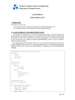
hown in this photograph is the landing of the Atlantis Space Shuttle Orbiter.
This chapter discusses the materials that are used for its outer airframe’s thermal
protection system. [Photograph courtesy the National Aeronautics and Space
Administration (NASA).]
Why Study Materials Selection and Design Considerations?
Perhaps one of the most important tasks that an engineer may be called upon to perform is that of materials selection with regard to component design.
Inappropriate or improper decisions can be disastrous from both economic and safety perspectives.
Therefore, it is essential that the engineering stu-
S-324
dent become familiar with and versed in the procedures and protocols that are normally employed in
this process. This chapter discusses materials selection issues in several contexts and from various perspectives.
Learning Objectives
After careful study of this chapter you should be able to do the following:
1. Describe how the strength performance index for
a solid cylindrical shaft is determined.
2. Describe the manner in which materials selection charts are employed in the materials selection process.
3. Briefly describe the steps that are used to ascertain whether or not a particular metal alloy is
suitable for use in an automobile valve spring.
4. List and briefly explain six biocompatibility considerations relative to materials that are employed in artificial hip replacements.
5. Name the four components found in the artificial
hip replacement, and, for each, list its specific
material requirements.
6. (a) Name the three components of the thermal
protection system for the Space Shuttle Orbiter.
(b) Describe the composition, microstructure,
and general properties of the ceramic tiles that
are used on the Space Shuttle Orbiter.
7. Describe the components and their functions for
an integrated circuit leadframe.
8. (a) Name and briefly describe the three processes
that are carried out during integrated circuit
packaging. (b) Note property requirements for
each of these processes, and, in addition, cite at
least two materials that are employed.
20.1 INTRODUCTION
Virtually the entire book to this point has dealt with the properties of various
materials, how the properties of a specific material are dependent on its structure,
and, in many cases, how structure may be fashioned by the processing technique
that is employed during production. Of late, there has been a trend to emphasize
the element of design in engineering pedagogy. To a materials scientist or materials
engineer, design can be taken in several contexts. First of all, it can mean designing
new materials having unique property combinations. Alternatively, design can involve selecting a new material having a better combination of characteristics for a
specific application; choice of material cannot be made without consideration of
necessary manufacturing processes (e.g., forming, welding, etc.), which also rely on
material properties. Or, finally, design might mean developing a process for producing a material having better properties.
One particularly effective technique for teaching design principles is the case
study method. With this technique, the solutions to real-life engineering problems
are carefully analyzed in detail so that the student may observe the procedures and
rationale that are involved in the decision-making process. We have chosen to
perform five case studies which draw upon principles that were introduced in
previous chapters. These five studies involve materials that are used for the following: (1) a torsionally stressed cylindrical shaft; (2) an automobile valve spring; (3)
the artificial total hip replacement; (4) the thermal protection system on the Space
Shuttle Orbiter; and (5) integrated circuit packages.
MATERIALS SELECTION FOR A TORSIONALLY
STRESSED CYLINDRICAL SHAFT
We begin by addressing the design process from the perspective of materials selection; that is, for some application, selecting a material having a desirable or optimum
property or combination of properties. Elements of this materials selection process
involve deciding on the constraints of the problem, and, from these, establishing
criteria that can be used in materials selection to maximize performance.
The component or structural element we have chosen to discuss is a solid
cylindrical shaft that is subjected to a torsional stress. Strength of the shaft will be
S-325
S-326
●
Chapter 20 / Materials Selection and Design Considerations
considered in detail, and criteria will be developed for the maximization of strength
with respect to both minimum material mass and minimum cost. Other parameters
and properties that may be important in this selection process are also discussed
briefly.
20.2 STRENGTH
For this portion of the problem, we will establish a criterion for selection of light
and strong materials for this shaft. It will be assumed that the twisting moment and
length of the shaft are specified, whereas the radius (or cross-sectional area) may
be varied. We develop an expression for the mass of material required in terms of
twisting moment, shaft length, and density and strength of the material. Using this
expression, it will be possible to evaluate the performance—that is, maximize the
strength of this torsionally stressed shaft with respect to mass and, in addition,
relative to material cost.
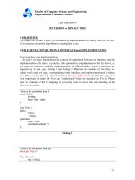
Consider the cylindrical shaft of length L and radius r, as shown in Figure 20.1.
The application of twisting moment (or torque), Mt produces an angle of twist .
Shear stress at radius r is defined by the equation
ϭ
Mt r
J
(20.1)
Here, J is the polar moment of inertia, which for a solid cylinder is
Jϭ
ȏr4
2
(20.2)
ϭ
2Mt
ȏr 3
(20.3)
Thus,
A safe design calls for the shaft to be able to sustain some twisting moment without
fracture. In order to establish a materials selection criterion for a light and strong
material, we replace the shear stress in Equation 20.3 with the shear strength of
the material f divided by a factor of safety N, as
f 2Mt
ϭ
N ȏr 3
(20.4)
It is now necessary to take into consideration material mass. The mass m of
any given quantity of material is just the product of its density () and volume.
Since the volume of a cylinder is just ȏr 2L, then
m ϭ ȏr 2L
Mt
L
r
(20.5)
FIGURE 20.1 A solid cylindrical shaft that
experiences an angle of twist in response to
the application of a twisting moment Mt .
20.2 Strength
●
S-327
Or, the radius of the shaft in terms of its mass is just
rϭ
ΊȏLm
(20.6)
Substitution of this r expression into Equation 20.4 leads to
f
ϭ
N
2Mt
ȏ
ͩΊ ͪ
ϭ 2Mt
m
ȏL
3
Ί
ȏL3 3
m3
(20.7)
Solving this expression for the mass m yields
m ϭ (2NMt )2/3(ȏ1/3L)
ͩ ͪ
f2/3
(20.8)
The parameters on the right-hand side of this equation are grouped into three sets
of parentheses. Those contained within the first set (i.e., N and Mt ) relate to the
safe functioning of the shaft. Within the second parentheses is L, a geometric
parameter. And, finally, the material properties of density and strength are contained within the last set.
The upshot of Equation 20.8 is that the best materials to be used for a light
shaft which can safely sustain a specified twisting moment are those having low
/ f2/3 ratios. In terms of material suitability, it is sometimes preferable to work
with what is termed a performance index, P, which is just the reciprocal of this
ratio; that is
Pϭ
f2/3
(20.9)
In this context we want to utilize a material having a large performance index.
At this point it becomes necessary to examine the performance indices of a
variety of potential materials. This procedure is expedited by the utilization of what
are termed materials selection charts.1 These are plots of the values of one material
property versus those of another property. Both axes are scaled logarithmically
and usually span about five orders of magnitude, so as to include the properties of
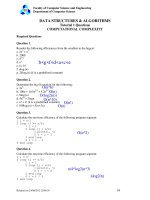
virtually all materials. For example, for our problem, the chart of interest is logarithm
of strength versus logarithm of density, which is shown in Figure 20.2.2 It may be
noted on this plot that materials of a particular type (e.g., woods, engineering
polymers, etc.) cluster together and are enclosed within an envelope delineated
with a bold line. Subclasses within these clusters are enclosed using finer lines.
1
A comprehensive collection of these charts may be found in M. F. Ashby, Materials Selection
in Mechanical Design, Pergamon Press, Oxford, 1992.
2
Strength for metals and polymers is taken as yield strength, for ceramics and glasses,
compressive strength, for elastomers, tear strength, and for composites, tensile failure
strength.
S-328
●
Chapter 20 / Materials Selection and Design Considerations
10,000
Engineering
ceramics
Diamond
Si3N4
Sialons
Al2O3
SiC
B
Glasses
Engineering
composites
KFRP
CFRP Be
Ge
Steels
Pottery
KFRP
P = 100
Strength (MPa)
Fir
Parallel
to Grain
Wood
Products
Ni Alloys
Cu Alloys
Zn
Alloys
Lead
Alloys
Cement
Concrete
Porous
ceramics
PU
LDPE
Cast
Irons
Engineering
alloys
Epoxies
Polyesters
HDPE
PTFE
Ash
Oak
Pine
Fir
Perpendicular
to Grain
Mo Alloys
MEL
PVC
PS
Woods
10
Stone,
Rock
PP
Balsa
P = 30
Al Alloys
Mg
Alloys
Nylons
PMMA
W Alloys
Ti
Alloys
GFRP
Laminates
Ash
Oak
Pine
Engineering
alloys
Cermets
MgO
Si
CFRP
GFRP
UNIPLY
1000
100
ZrO2
Silicone
Engineering
polymers
Soft
Butyl
Balsa
Elastomers
P = 10
Polymer
foams
Cork
1
P=3
0.1
0.1
0.3
1
3
10
30
Density (Mg /m3)
FIGURE 20.2 Strength versus density materials selection chart. Design guidelines
for performance indices of 3, 10, 30, and 100 (MPa)2/3m3 /Mg have been
constructed, all having a slope of . (Adapted from M. F. Ashby, Materials
Selection in Mechanical Design. Copyright 1992. Reprinted by permission of
Butterworth-Heinemann Ltd.)
Now, taking the logarithm of both sides of Equation 20.9 and rearranging yields
log f ϭ log ϩ log P
(20.10)
This expression tells us that a plot of log f versus log will yield a family of straight
and parallel lines all having a slope of ; each line in the family corresponds to a
different performance index, P. These lines are termed design guidelines, and four
20.2 Strength
●
S-329
have been included in Figure 20.2 for P values of 3, 10, 30, and 100 (MPa)2/3m3 /
Mg. All materials that lie on one of these lines will perform equally well in terms
of strength-per-mass basis; materials whose positions lie above a particular line
will have higher performance indices, while those lying below will exhibit poorer
performances. For example, a material on the P ϭ 30 line will yield the same
strength with one-third the mass as another material that lies along the P ϭ 10 line.
10,000
Engineering
ceramics
Diamond
Si3N4
Sialons
Al2O3
SiC
B
Glasses
Engineering
composites
KFRP
CFRP Be
Ge
Steels
Pottery
KFRP
Ash
Oak
Pine
Strength (MPa)
Fir
Parallel
to Grain
Wood
Products
10
P = 10
(MPa)2/3 m3/Mg
Stone,
Rock
Epoxies
Polyesters
HDPE
PTFE
Ni Alloys
Cu Alloys
Zn
Alloys
Lead
Alloys
Cement
Concrete
Porous
ceramics
PU
LDPE
Cast
Irons
MEL
PVC
PS
Ash
Oak
Pine
Fir
Perpendicular
to Grain
Mo Alloys
Engineering
alloys
PP
Balsa
Woods
Al Alloys
Mg
Alloys
Nylons
PMMA
W Alloys
Ti
Alloys
GFRP
Laminates
300 MPa
Engineering
alloys
Cermets
MgO
Si
CFRP
GFRP
UNIPLY
1000
100
ZrO2
Silicone
Engineering
polymers
Soft
Butyl
Balsa
Elastomers
Polymer
foams
Cork
1
0.1
0.1
0.3
1
3
10
Density (Mg /m3)
FIGURE 20.3 Strength versus density materials selection chart. Those materials
lying within the shaded region are acceptable candidates for a solid cylindrical
shaft which has a mass-strength performance index in excess of 10 (MPa)2/3m3 /
Mg, and a strength of at least 300 MPa (43,500 psi). (Adapted from M. F.
Ashby, Materials Selection in Mechanical Design. Copyright 1992. Reprinted
by permission of Butterworth-Heinemann Ltd.)
30