FORMING COLUMN CRYSTAL MICROSTRUCTURE SAMPLE BASED ON THE OPTIMIZED SINGLE CLADDING TRACK CHARACTERISTICS tạo mẫu NHANH tổ CHỨC TINH THỂ HÌNH TRỤ TRÊN cơ sở tối ưu hóa đặc TÍNH của ĐƯỜNG QUÉT đơn
Bạn đang xem bản rút gọn của tài liệu. Xem và tải ngay bản đầy đủ của tài liệu tại đây (774.63 KB, 8 trang )
Kỷ yếu hội nghị khoa học và công nghệ toàn quốc về cơ khí - Lần thứ IV
FORMING COLUMN CRYSTAL MICROSTRUCTURE SAMPLE BASED
ON THE OPTIMIZED SINGLE CLADDING TRACK CHARACTERISTICS
TẠO MẪU NHANH TỔ CHỨC TINH THỂ HÌNH TRỤ TRÊN CƠ SỞ
TỐI ƯU HÓA ĐẶC TÍNH CỦA ĐƯỜNG QUÉT ĐƠN
1Đỗ
Xuân Tươi, 1Đoàn Tất Khoa, 2Nguyễn Anh Tú
1
Học viện Kỹ thuật quân sự
2
Trung tâm 80 - Cục tác chiến điện tử - BTTM
ABSTRACT
This paper investigated the influence of the cladding conditions on the characteristics of
single cladding track, which is elementary unit in Direct Laser Forming (DLF). Single
cladding tracks were clad with different technology parameter sets, in which laser power,
scanning speed and powder feeding rate were all changed. The characteristics of all tracks
were measured. Based on the analysis of the results, the forming conditions, which can make
samples with column crystal microstructure, were obtained. The results showed that from
determining single cladding track characteristics, obtaining them by optimization of
technology parameters, DZ125L super-alloy sample with column crystal microstructure can
be formed by DLF. It can be used in the approach to form parts which have the microstructure
of layer by layer epitaxial growth of column crystal.
Keywords: Direct Laser Forming, single cladding track, column crystal microstructure,
epitaxial growth, DZ125L super-alloy.
TÓM TẮT
Bài báo nghiên cứu sự ảnh hưởng của các tham số công nghệ đến đặc tính của đường
quét đơn, phần tử cơ bản nhất của quá trình tạo mẫu nhanh trực tiếp bằng Laser (DLF). Các
đường quét đơn được tạo ra với các bộ tham số công nghệ khác nhau bằng cách thay đổi công
suất Laser, tốc độ quét và tốc độ cấp bột kim loại. Đặc tính của các đường quét đơn được đo
đạc và phân tích, từ đó đã xác định được dải các tham số công nghệ để có thể tạo ra mẫu thí
nghiệm có tổ chức tinh thể hình trụ. Kết quả nghiên cứu chỉ ra rằng, tối ưu hóa các tham số
công nghệ có thể tạo ra mẫu thí nghiệm từ hợp kim chịu nhiệt DZ125L với tổ chức tinh thể
hình trụ phát triển liên tục khi sử dụng công nghệ tạo mẫu nhanh trực tiếp bằng Laser. Đây là
kết quả quan trọng giúp cho quá trình nghiên cứu tạo mẫu nhanh các chi tiết yêu cầu có tổ
chức tinh thể hình trụ phát triển liên tục.
Từ khóa: tạo mẫu trực tiếp bằng Laser, đường quét đơn, tổ chức tinh thể hình trụ, phát
triển liên tục, hợp kim chịu nhiệt DZ125L.
1. INTRODUCTION
Direct Laser Forming (DLF) is a novel layer additive manufacturing technology. There
are some other similar technologies using the same principle as DLF are Laser Engineered
Net Shaping (LENS), Laser Direct Metal Forming (LDMF), Direct Metal Deposition
(DMD),…, which base on rapid prototyping and laser cladding technique [1-3, 7]. In DLF,
dense metal parts are fabricated directly from CAD files line by line and layer by layer
without constraints on part shape and powder material and without using any tooling, and it
has been a hot topic in the advanced manufacturing fields. The DLF supports many types of
metals including stainless steels (316 and 304); Ni based super-alloys (Inconel 625, 690, and
614
Kỷ yếu hội nghị khoa học và công nghệ toàn quốc về cơ khí - Lần thứ IV
718, FGH95, DZ408, DZ125L); cobalt-chrome; and Ti-6Al-4V titanium alloy. Parts formed
by DLF, as by any other technologies, are all required to get suitable morphology accuracy,
microstructure evolution and material performance,.etc. For some components like turbine
blade, which usually formed by Ni based super-alloys and used in aircraft engine and turbine
machines, microstructure evolution of material is the key factor, it needs columnar crystal
microstructure. At the beginning, turbine blade was manufactured by forging, it was then
successfully casted in U.S.A in 1950, and the forging process was gradually replaced by cast
process. In recent years, investigation into manufacturing turbine blade by laser application
processes has been carried out all over the world, including of feeding powder and spreading
powder methods. It showed that turbine blade can be fabricated by Selective Laser Melting SLM, by DLF [4-5] or by DMD [6]. However, the mechanical performance of the parts
fabricated by the above-mentioned methods has not been reported sufficiently. There were
some investigations in repairing and coating on directionally solidified Ni based super-alloys
by DLF [8-10], there were also reports in fabrication of directional solidification Ni based
super-alloy samples [11], whereas all of them showed samples with six to eight layers high.
At present, forming column crystal metal part by DLF still remains a great challenge.
DZ125L is a high performance Ni based super-alloy, designed in China for turbine
application in advanced gas turbine engines. Using DZ125L for the experiments, this paper
systematically investigated the influence of the main forming condition parameters as laser
power, scanning speed, powder feed rate on the characteristics of single cladding track, the
elementary unit in DLF. It also developed an analysis method to find out optimal forming
parameters. The result showed that by determining characteristics of single cladding track,
obtaining them by optimized technological parameters, DZ125L super-alloy thin wall part
with more than twenty layers column crystal microstructure could be formed by DLF.
2. EXPERIMENTAL PROCEDURE
2.1. Materials and equipment
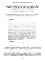
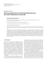
The experiments were carried out by the system as shown in Figure 1. The DLF process
was performed by independently developed XJTU-I machines which includes a Nd:YAG
laser with a 1 kW maximum output power (wavelength 1063 nm, spot diameter of 0.48 mm,
the laser beam was guided to the workstation through an optical fiber and focused by an optic)
and a three-axis CNC linkage worktable and a powder feeder with a coaxial feeding nozzle
and a gas protection device. The processing chamber of the system was protected from
oxidation by argon gas.
Figure 1. Schematic diagram of experiment setup
615
Kỷ yếu hội nghị khoa học và công nghệ toàn quốc về cơ khí - Lần thứ IV
The powder used was Ni based super-alloy DZ125L with spherical shape and smooth
surface. Additionally, the DZ125L particle size distributes of about 30-60 µm and the mean
particle size of about 45 µm. The substrate was the same material, machined from single
crystalline cast ingots, with the <001> orientation normal to the surface, and its dimension
was Φ50x3.5. The compositions of the powder and the substrate are shown in Table 1.
Material
Table 1. The compositions of the powder and the substrate (wt %)
C
Cr
Co
Mo
W
Al
Ti
Ta
B
Ni
Substrate
0.07
9.09
10.00
2.09
7.17
4.48
3.05
3.64
0.011
Balance
Powder
0.09
9.70
9.64
2.18
7.14
4.90
3.12
3.78
0.015
Balance
2.2. Processing
Before doing the experiments, the powder was dried in a vacuum oven at 2000C for 2
hours to remove the moisture and improve the flow ability. The substrate was polished and
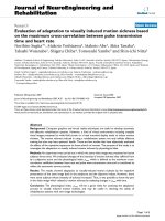
then cleaned by acetone before being installed on the forming worktable and leveled. Single
cladding tracks (20 mm in length) were prepared (Figure 2a) using different laser powers P,
scanning speeds V and powder feeding rates Mp (as shown in Table 2). Three separate tracks
were prepared with each parameter set of (M p , P, V) and the values of each parameter in the
set of (M P , P, V) were selected according to the preliminary basic research results. Thin wall
samples were formed based on the analysis of single cladding tracks characteristics (Figure 2b,
2c). No pre-heat or post-deposition heat treatment of the deposited samples was applied. The
samples were cut for characterization with wire EDM. All samples were mounted and
prepared in accordance with standard metallographic procedures. The topography
characteristics and the microstructure characteristics of each sample were analyzed using
VH3000 optical microscope (made in Japan by the KEYENCE).
The cross section characteristic parameters of each single track was measured, the
results were calculated to find out the mean values. Finally, showing the influence of the
process parameters on the single cladding track characteristic diagrams were obtained (Figure
4 and Figure 5). Technology parameters, from which can clad single tracks with suitable
morphology and microstructure characteristics, were obtained from analyzing the diagrams,
after that thin wall sample with column crystal microstructure was formed.
Table 2. Technology parameters for single cladding tracks in DLF
M p (g.min-1)
P (W)
4.9*
190, 210, 230, 250, 270
V (mm.s-1)
6, 8, 10, 12
Shielding gas (l.min-1)
4**
Protecting gas (l.min-1)
6**
Track number of each parameter set
3
*
The preliminary basic research indicated that 4.9 g.min- 1 remained stable cladding tracks,
less than or more than this value released poor samples.
**
Shielding gas and protecting gas outputs influence very little to the single cladding track
morphology and they can be ignored.
616
Kỷ yếu hội nghị khoa học và công nghệ toàn quốc về cơ khí - Lần thứ IV
Figure 2. Sketch of single cladding tracks (a), thin wall samples (b and c)
3. RESULTS AND DISCUSSION
3.1. Influence of the process parameters on the single cladding track characteristics
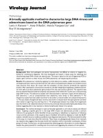
The cladding track morphology is described with the cladding track width W (µm), the
cladding track height H (µm), the cladding track depth h (µm) and the height of column
crystal microstructure zone h ds (µm). All of them are defined in the cladding profile as shown
in Figure 3. The single track morphology parameters were measured after the experiments.
From each set of (M P , P, V), which used for three separate tracks, we got three value sets of
(W, H, h and h ds ). These values then calculated to find out each mean value of W, H, h and
h ds , and finally expressed by the diagrams in Figure 4.
Figure 3. Single cladding track cross section parameters
After polishing and etching the samples, directional dendrite structure in the substrate
was released. The refined dendrite structure in the deposit zone showed an epitaxial growth
parallel with the substrate dendrite direction. The epitaxial growth also verified the nature of
bonding at the interface to be metallurgical. Compared with the dendrite size of the substrate
metal, the primary dendrite size in the deposit zone is approximately 50-70 times smaller.
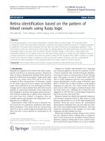
From Figure 4 we can see that, with different technology parameters used, single
cladding track cross sections with different characteristic values were released. The result
showed that the increase in laser power resulted in the increase in the cladding track width W
and the cladding track depth h (Figure 4a and 4c). The increase in laser power resulted in the
decrease in the height of column crystal microstructure zone h ds (Figure 4d). For the cladding
track height H, its value was relatively stable when the scanning speed of 8 mm.s-1 or 10
mm.s-1, too small when the scanning speed of 12 mm.s-1 and big when the scanning speed of 6
mm.s-1 (Figure 4c). The height of column crystal microstructure zone h ds is the most
important parameter, it must be relatively bigger than zero to make the subsequent layer with
an epitaxial growth parallel to the previous ones. Figure 4d also indicated that laser power
should not be too high, and the suitable value is not higher than 250W.
617
Kỷ yếu hội nghị khoa học và công nghệ toàn quốc về cơ khí - Lần thứ IV
Figure 4. Influence of the main process parameters on the single cladding track
characteristics
(a) cladding track width W (µm), (b) cladding track height H (µm), (c) cladding track depth h
(µm), (d) the height of column crystal microstructure zone h ds (µm)
Figure 5. The difference values of (H-h ds -h) according
to different technology parameter sets
Moreover, the dendrite layer (multidirectional zone) and an inter-dendrite shrinkage
should be thoroughly re-melted to ensure the densification and epitaxial growth between the
depositing layer and the previous one. From Figure 3, the difference value of (H-h ds ) must be
smaller than h, it means that the difference value of (H-h ds -h) must be negative. The calculation
result, which is shown in Figure 5, indicated that the suitable condition is obtained when the
scanning speed is 10 mm.s-1 or 12 mm.s-1 with laser power less than 270W. Low scanning
speed of 6 mm.s-1 or 8 mm.s-1 (with laser power less than 230W) is not suitable, 8 mm.s-1
scanning speed is suitable only when laser power relatively high (in range of 230W - 255W).
3.2. DZ125L super-alloy thin wall part forming
From above analysis, DZ125L super-alloy thin wall parts were formed (Figure 2 and
Figure 6). The forming conditions with different technology parameter sets were used as
shown in Table 3.
618
Kỷ yếu hội nghị khoa học và công nghệ toàn quốc về cơ khí - Lần thứ IV
Samples
1
2
3
4
Table 3. Technology parameters for thin wall samples
Laser
Scanning
Powder
Caring
Protect
Standoff
power
velocity
Feed rate
gas rate
Gas rate distance
(W)
(mm)
(mm.s-1)
(g.min-1) (l.min-1) (l.min-1)
200
250
270
240, 230,
220, 210
10
10
10
10
4.9
4.9
4.9
4.9
4
4
4
4
6
6
6
6
0.1
0.1
0.1
0.1
Number
of layers
20
20
20
10,10,
20,40
Figure 6. The first layers of thin wall samples
(a) sample 1, (b) sample 3, (c) sample 2, (d) sample 4
The results showed a strong metallurgical bonding has been achieved between the thin
wall and the substrate. With sample 1 (Figure 2b and Figure 6a), although the technology
parameters met the requirements from h ds and (H-h-h ds ), but with the small values of W, H
and h, the forming quality was very poor. Therefore its microstructure was also very poor and
without column crystal structure (Figure 6a). Lowering of laser power also resulted in poor
samples. With 270W and higher laser power, thin wall samples could be formed smoothly,
there was directional tendency of the microstructure in several first layers, but it did not show
epitaxial column crystal structure (Figure 6b).
The samples formed with the laser power of 250W and lower showed good appearances,
without any crack, and the microstructure achieved directional column crystal, which shown
in Figure 2 and Figure 6c, 6d. With proper deposition parameters, it was able to produce
continued directional growth in the deposition zone over twenty layers of sample 4 (Figure 7)
comparing to eight layers of sample 2. As subsequent layers were deposited, the solidification
substructure changed from directional columnar structure to dendrite structure and resulted in
the decrease in the directional columnar zone width.
The change in solidification substructure can be explained by using the welding
solidification theory [12]. The ratio of the temperature gradient G to the growth rate R, in G/R,
619
Kỷ yếu hội nghị khoa học và công nghệ toàn quốc về cơ khí - Lần thứ IV
governs the mode of solidification. In this case, the layer deposition was accompanied by the
deposition of laser heat flow. Therefore, higher layer was deposited with lower ratio of G/R
because the temperature of the layers increased one by one. Moreover, with the increase in the
deposited layer number, heat flow, dispersed into the substrate by conduction gradually
decreased due to the increase in both the temperature and the distance to the substrate.
Meanwhile, heat flow also dispersed into the surrounding media simultaneously by
convection and radiation increasingly because of the increase in temperature.
4. CONCLUSIONS
Determining single cladding track characteristics, which obtained by optimizing process
parameters through experiments, could help to form DZ125L super-alloy thin wall part with
directional column microstructure successfully. Because of the decrease in the ratio of G/R
and the change of heat flow dispersing, the width of the column structure zone was decreased
with the increase in deposited layer number. By proper regulating laser power in accordance
with the increase in deposited layer number, it has likely improved the column crystal
microstructure of the part, and the column crystal structure grew with more than twenty layers
in height. The investigation result indicated that, laser power should not be too high and the
suitable scanning speed should be 10mm.s-1. We can use the result of this research in the
approach to form parts which have the microstructure of layer by layer epitaxial growth of
column crystal.
ACKNOWLEDGEMENTS
The authors gratefully acknowledge for the State Basic Research Key Projects of China
through Grant no. 2007CB707704; National Natural Science Foundation of China through
Grant no. 51005177 and no. 51275392.
REFERENCES
[1]
Wang HM, Duan G. Wear and corrosion behavior of laser clad Cr3Si reinforced
intermetallic composite coatings. Intermetallics 2003; 11: 755-62.
[2]
Tan H, Chen J, Zhang FY, Lin X, Huang WD. Process analysis for laser solid forming
of thin-wall structure. Int J Mach Tools Manu 2010; 50: 1-8.
[3]
Wohlers Associates, Inc. Additive Manufacturing and 3D Printing State of the Industry,
Annual Worldwide Progress Report. ISBN 0-9754429-7-X, Wohlers report 2011.
[4]
/>
[5]
.
[6]
J. Choi, B. Dutta, J. Mazumder. Spatial Control of Crystal Texture by Laser DMD
Process. Supplemental Proceedings: Volume 1: Fabrication, Materials, Processing and
Properties TMS (The Minerals, Metals & Materials Society), 2009, 405-413.
[7]
Venkatakrishanan K, Sivakumar NR, Hee CW, et al. Direct fabrication of surface-relief
grating by interferometric technique using femtosecond laser. Appl Phys A: Mater Sci
Process 2003; 77(7): 959-63.
620
Kỷ yếu hội nghị khoa học và công nghệ toàn quốc về cơ khí - Lần thứ IV
[8]
Leijun Li. Repair of directionally solidified superalloy GTD-111 by Laser Engineered
Net Shaping. J Mater Sci (2006) 41: 7886-7893.
[9]
R. Vilar, E.C. Santos, P.N. Ferreira, N. Franco, R.C. da Silva. Structure of NiCrAlY
coatings deposited on single-crystal alloy turbine blade material by laser cladding. Acta
Materialia 57 (2009) 5292–5302.
[10] M. Gäumann, C. Bezençon, P. Canalis, W. Kurz. Single-crystal laser deposition of
superalloys: processing–microstructure maps. Acta mater. 49 (2001) 1051–1062.
[11] Feng Liping, Huang Weidong, Lin Xin, Yang Haiou, Li Yanmin, yang Jian. Laser
multilayers cladding experiment on the DD3 single crystal using FGH-95 powder:
Investigation on the microstructure of single crystal cladding layer. Chinese journal of
Aeronautics. May 2002. Vol. 15, No. 2.
[12] Messler RW Jr (1999) Principles of welding. John Wiley & Sons, p428.
THÔNG TIN TÁC GIẢ
1.
Đỗ Xuân Tươi (Giảng viên chính - tiến sỹ; Học viện Kỹ thuật quân sự - Số 236 Hoàng
Quốc Việt - Cầu Giấy - Hà Nội; Email: )
2.
Đoàn Tất Khoa (Giảng viên - thạc sỹ; Học viện Kỹ thuật Quân sự - Số 236 Hoàng Quốc
Việt - Cầu Giấy - Hà Nội; Email: )
3.
Nguyễn Anh Tú (Thạc sỹ; Trung tâm 80 - Cục tác chiến điện tử - BTTM - Số 15 Hoàng
Sâm - Cầu Giấy - Hà Nội; Email: )
621