Latest Developments on Plastics Recycling Technologies in Japan
Bạn đang xem bản rút gọn của tài liệu. Xem và tải ngay bản đầy đủ của tài liệu tại đây (1.72 MB, 11 trang )
Contents
1. Trend of waste plastic recycling in Japan
2. Containers and Packaging Recycling Law (CPRL)
3. Recycling technologies
3.1 Existing technologies for CPRL
Latest Developments on Plastics Recycling
Technologies in Japan
Blast furnace reducing agent, Coke oven fuel, Gasification, Liquefaction
3.2 Expecting technologies for CPRL
RPF
3.3 New recycling technologies and systems
(1)Producing naphtha rich oil by catalyst cracking using spent FCC
August 30 2011 in Bangkok
catalyst
(2)Highly efficient recycling technology for waste multilayer films
(3)Mechanical Recycling Technology for Waste PVC wall covering
based on High-speed Centrifugal Beating Technology
Yamawaki Takashi
Plastic Waste Management Institute
1
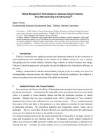
1. Trend of waste plastics recycling in Japan
Mechanical Recycling
Import
Resin
Production
11,210
Domestic
Consumption
8,430
Post-use
Discharge
8,460
Processing
Waste
480
Total
Discharge
9 120
9,120
Production
Waste
180
Domestic
Waste
4,440
2,000(22%)
Liquefaction,
Gasification,
Blast furnace
80
320(4%)
75
Densified-refuse
derived fuel
70
Reclaimed
Products
540
Industrial
Waste
4,680
Ut iliza tion ra t e(%)
420(5%)
Unit:1000t
Incineration with
power generation
3,280(36%)
Incineration with heat
utilization facility
1,160(13%)
Unutilized:2,710(21%)
65
60
55
50
Incineration without
power generation or heat
utilization facility
45
1,070(12%)
Landfilling
40
880(10%)
1999
2000
Source : Plastic Waste Management Institute
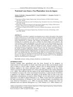
Figure-1 Flowchart of Plastic Products, Waste, and Recycling(2009)
2
Plastic utilization rate increased steadily reaching
79%(2009) of total plastic waste discharge.
Utilized:7,230(79%)
Export
(4)Tray
Tray--to
to--Tray recycling by “FPCO system”
(5)Advanced separation technology of shredded plastic mixture from
WEEE
(6)PET bottle to PET bottle by using mechanical process
3
Figure-2
2001
2002
2003
2004
Calender year
2005
2006
2007
2008
4
1
2. Containers and Packaging Recycling Law (CPRL)
Figure-4
Actual performance related to C&P plastics other than PET bottles
Designated
manufactures/users
Business entities utilizing
recycled products
Payment of
recycling
costs
The Japan C&P
Recycling Association
Supply
Consumers
Declaration for
amount of sorting
plastic waste
Payment of
recycling costs
Bidding
price
Supply
pp y
Recyclers
Municipalities
Sorted
collection
Sorted discharge
Transportation and recycling
of “items to meet sorting criteria”
Figure-3
5
6
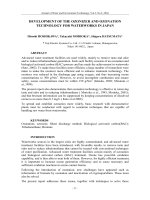
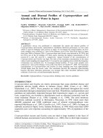
Figure-6
Figure-5
Large Scaled Chemical Recycling Facilities
Trends in bidding for the various recycling methods for
C&P plastics other than PET bottles
Nihon Steel (Muroran)
Coke Oven: 20,000t
16 Facilities:
Monomer 1
Blast furnace 3
Coke oven 6
Gasification 5
Liquefaction 1
(Total 500 Kt/y)
(complied with C&P recycling law, 2012)
Mogami kiko (Shinjo)
Liquefaction: 1,000t
Orix environmental resources
Gasification : 30,000t (Yorii)
JFE Steel (Chiba)
Gasification: 20,000t
Nippon Steel (Kimitsu)
Coke Oven: 50,000t
JFE Steel (Fukuyama)
Blast furnace/Coke Oven : 40,000t
JFE Steel (Kawasaki)
40,000t/30,000t
Blast furnace/Coke Oven
Kyoei cycle(Onoda)
Gasification: 25,000t
Nihon Steel (Yahata)
Coke Oven: 20,000t
Showa Denko(Kawasaki)
Gasification: 64,000t
Nihon Steel (Oita)
Cokes Oven: 25,000t
7
Mizushima ecoworks (Mizushama)
Gasification : 51,000t
PET Reverse (Kawasaki)
Monomer B to B: 27,500t
Kobe Steel (Kakogawa)
Blast furnace: 10,000t
Nihon Steel (Nagoya)
Coke Oven: 50,000t
8
2
3. Recycling technologies
(2)The flow seat of utilization for coke oven fuels
3.1 Existing recycling technologies for CPRL
(1)The flow seat of utilization for blast furnace reducing agents
Fe2O3+CH→Fe+CO2
+H2O
9
Figure-7
Source: Nippon Steel Co.
10
(3) The flow seat of utilization for gasification
Carbonization room
Figure-9
Figure-8
Source: JFE Steel Co.
Source: Nippon Steel Co.
11
Figure-10
Source: Ube Industries Ltd.
12
3
3.2 Expecting recycling technology for CPRL
(4)The flow seat of utilization for liquefaction
Source: Sapporo Plastic Recycling
Last year, this plant was closed.
Figure-11
13
Figure-14 Comparison of Liquefaction process
3.3 New recycling technologies
[existing cracking]
(1) Liquefaction by Catalyst Cracking using Spent FCC Catalyst
melting
dechlorination
pretreatment
Waste Plastic, Spent Catalyst,
Slaked Lime
Fixed
catalytic cracking
product
exhaust gas treatment
Fixed
Coole
r
[this catalytic cracking]
Fuel gas
pretreatment
product
catalytic cracking
vent
Heater
waste plastic
condenser
Oil/Gas Separator
Fuel
Heating
Furnace
feeder
Waste Catalyst
breaker
reflux
HCl gas
feeder
product oil
cracker
Residual
Substance
Source: The University of Kitakyusyu
15
vent
condenser
neutralization
Dechlorination
Agent
Figure-13
cracking
Spent
Catalyst
Rotational Dram
Air
14
Figure-12
cracker
Reduction
melting
dechlorination
residue
air-heating furnace
air-heating furnace
heavy oil
16 oil
cracked
4
WCCP Cracking (Bench Plant)
Results of PE Degradation using spent FCC Catalyst
Total outlet flow [wt%]
cooler
<Reaction Condition>
120
PE
425℃
PE-FCC
420℃
100
80
Temperature:420~480Ԩ
Agitation:2~5rpm
Reactor:300φ×1200L
Feed:2~20kg/hr
WCCP: waste container and
packaging plastic
<Chlorine>
60
40
20
0
0
30
60
90
120
150
180
Flow time [min]
11.5
1~2
45.0
4000
3000
2000
39
210
4
176
47
6
Figure-16-1
17
17
<Demonstration Plant>
Capacity : 80kg/h
47.6
41.5
46.0
50.1
3.9
18.3
39.9
5.3
43.0
36.4
52.8
58.1
40.9
8
47
12
13
189
128
20
1
Number of run [-]
Start up feed Ca(OH)2
55.8
0.3
0.6
16
9.1
40.8
Heavy oil
Diesel
Naphtha
Ca(OH)2
1000
0
3.8
8.1
5.8
4047
Fig15-2:Distribution of carbon number of products
DEMONSTRATION PLANT
OF WASTE PLASTIC CRACKING
<Product Oil>
5000
1
Dr
y
Aromatic
R esidua l C hlorine[ppm ]
0
oi
l
i-Paraffin
co
ke
22.5
de
se
l
30
ga
s
Oreffin
Used catalyst
he
av
y
11.0
Free catalyst
LP
G
60
40
35
30
25
20
15
10
5
0
Used Catalyst
Na
ph
th
a
Used
catalyst [wt%]
Percentage[wt%]
n-Paraffin
Free catalyzed
Ke
ro
se
ne
Fig15-1:On
Fig15
1:On the relationship between
outlet flow and flow time
Table1:Distribution ratio of products
Free
catalyst [wt%]
hopper
cracker
Ca(OH)2:50vol%
6
40.7
0.5
8
12
Number of run [-]
Figure-16-2
0.3
0.1
13
49.8
0.2
16
LPG
0.2
20
Ca(OH)2
Start up feed Ca(OH)2
18
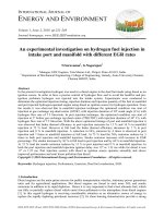
(2) Introduction of development of highly efficient
recycling technology for multilayer films
Background :
Feed : C&P Home waste, Recycles of home electronics, ASR
¾What is the multilayer film?
The composite film which laminates PET, PA as the functional layer to give gas
barrier property, pinhole resistant, and so on and PE, PP as the sealant layer.
Figure-17<Flow of Demonstration Plant>
¾Situation of waste treatment of the multilayer film
大気放出
chain block
A001電動チェーンブロック
Most of multilayer films have been being disposed of (incineration, or
landfill), as these cannot be recycled to materials with required strength.
The mill ends of these multilayer films of 15,000 t/month (estimate value) are
discharged from printing factories in Japan.
S002
排気筒
原料
feed
blower
B004排ガス誘引ブロワ
V001
材料受入ホッパ
hopper
V002
feeder
投入ホッパ
廃水(産廃)
Waste
water
H001分解油冷却器
oil cooler
R001
プラスチック液化装置
残渣排出
(産廃)
Objective :
B001
blower
生成ガスブロワ
B003希釈空気ブロワ
air blower
¾ Utilization of these multilayer films as recycled material by commpatibilization
technology of different kinds of plastics.
¾ Converting to economically advantageous sheet by achieving both compatibilization and molding to sheets from shredded flakes of mill end of multilayer films.
B002燃焼空気ブロワ
air blower
cracker
waste
catalyst
<Cracker>
F001熱風発生炉
T004
水封タンク
LPG
(supplement)
LPG(補助燃料)
separator
T003払出しタンク
T002
分解油タンク
product oil
生成油(産廃)
P001分解油ポンプ
P002払出しポンプ
19
19
20
5
Conventional process
Compatibilizer
shredding
Multilayer film
Figure-19 Effect of compatibilization
Flake
Modification
and Kneading
Pellet
Pellet
Sh t extruding
Sheet
t di
Sh t
Sheet
New process
SPE90A/JPP90A=75/25
Without compatibilizer
Tensile strength=10MPa
Elongation=10%
Two steps
Compatibilizer
shredding
Multilayer film
SPE90A/JPP90A=75/25
With 5% of compatibilizer
Tensile strength=10MPa
Elongation=300%
Flake
Modification, Kneading
and Sheet extruding
Sheet
Direct sheet extrusion
Figure-18 Comparison between the conventional process and the
new process
21
Direct sheet extrusion system
22
The sheet which satisfies the following point, can be extruded directly
with using shredded flake of multilayer film.
Big Tank Feeder System
Acceptable range of wall thickness أ10%
Tensile strength ؤ10MPa(MD、TD)
Fish eye or Foreign matter : Unidentified
Compatibilizer Slot
Gear Pump
T-Die
Figure-21 Target of direct sheet extrusion
First extruder
: Co-Rotating Twin Screw Extruder equipped Screen Changer,
Screw Diameter 105mm
Second extruder : Single Screw Extruder equipped Screen Changer and
Gear Pump, Screw Diameter 100mm, L/D=28
Figure-20 Outline of direct sheet extrusion system
23
Flake of multilayer film
Outlet of first extruder
Condition of sheet extrusion
Figure-22 Situation of direct sheet extrusion
24
6
(3) Development of Mechanical Recycling Technology for Waste PVC wall
covering based on High-speed Centrifugal Beating Technology
Application example
Concrete panel
500 concrete panels (plywood covered by the sheet) are made for trial purposes,
and the performance assessment in the site is under way.
PVC wall covering
Production
180 thousand tons
PVC
32%
rear:
pulp
Advantage : easy removable, recyclable use
Plasti
cizer
16%
front:resin
C CO3
CaCO
29%
PULP
21%
Figure-23 Construction site
25
Waste from
construction
Production
waste
Figure-24 Plywood covered by sheet
Waste
Figure-25
Waste from
dismantling
100 thousand tons
Other
2%
26
26
Structure of High-speed Centrifugal Beating Machine
System flow of this technology
Shredding
Waste
Wall covering
Pulverization
Separation
(recovery of pulp)
pulp
pulp
new
resin
pulp
new
shredder
beater
Rotary separator
Separation
cyclone
(recovery of resin)
resin
new
Figure-26
27
Separation tower
Figure-27
Vibrating sieve
resin
28
28
7
PVC wall covering
(4) Tray
Tray--to
to--Tray recycling by “FPCO system”
Dining
table
Retail
Delivery
Consumers
Supermarkets,
etc.
Packaging
wholesalers
FPCO
Structure of system using collaborating companies (FPCO System)
Washing &
drying
Collection
Storing
Picking-up
& recycling
Pulp
PVC resin
Production
Raw
material
Tasks of each
player
___ Supermarket
____
Packaging
Materials
Collection
FPCO
box
Sparkle
Gleam
Consumers are requested to
separate used styrofoam trays
from other garbage, and to
wash and dry them.
Back paper for wall covering
Used trays brought in by
consumers are accumulated in
collection bins at supermarkets
and other stores. This makes for
stronger ties between
consumers and supermarkets.
Packaging wholesalers use their
trucks to pick up the used trays
on their way back from delivery
runs to supermarkets, etc., and
temporarily store them on their
premises.
When our trucks deliver trays to
wholesalers, they bring the used
trays back with them on the return
trip. This method of collecting the
used trays is unique to FPCO,
which makes its own deliveries.
Used trays are also recovered via municipalities and a designated corporation.
Items meeting sorting
criteria
Municipalities
Floor mat for automobile
Collection & sorting
Form floor material
* Designated corporation route: Collection route prescribed
by the Containers and Packaging Recycling Law.
29
Figure-28
Consolidation of final processes
(improvement in quality of recycled raw materials)
Outsourced treatment
Designated corporation
Japan Containers and
Packaging Recycling
Association
30
Figure-29
Source : FP CORPORATION
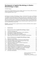
Products from recycled materials (Tray-to-Tray)
Washing water filter machine
Alkaline concentration adjustment tank
Eco hot water Hot water tank
Alkalescent
Heat exchanger
supply system
detergent tank
Primary cleaning
Secondary cleaning
Rinsing
Plant Mill-End Pellets
Blend (70% plant mill-end, 30% collected
tray pellets)
Raw material
Old line
Recycled
sheet
Mold
Raw film
sheet
Sheeting Process
*Virgin raw material is not
used at the sheet step.
Figure-30
31
FP CORPORATION
Virgin film upper/lower laminate
(film mass is 20% of tray mass)
Oven
Blowing agent
Extruder
Recycled Pellets of Collected Trays
Cut
Printed-pattern
tray pellets
PSP new washing line
White-tray pellets
zPSP: Into 3 plants in Kanto, Shin-Chubu and Fukuyama
Sold as construction raw
materials
(Pilings, artificial wood,
wood flooring, etc.)
Eco Tray
Mill ends after
cutting are used
again to make
pellets
Vacuum
suction
Raw film
Molded product
sheet
Molding Process
Accounts for 20% of general-purpose trays
circulating in the Market.
Eco trays have an eco symbol.
32
Figure-31
FP CORPORATION
8
(5) Advanced separation technology of shredded plastic
mixture from WEEE
Ensuring Eco Tray Safety
WEEE
A standards inspection of recycled raw
material is performed monthly by the
Japan Inspection Association of Food and
Food Industry Environment at every
recycling plant.
The Japan Food Research Laboratories are
requested to test the Eco (recycled) Trays to
verify
if that
th t they
th satisfy
ti f the
th corresponding
di
regulations and standards.
Vegetable
case
【冷蔵庫
In refrigerator
野菜ケース】
Hygiene Test Certificate
Motor, Compressor
Manual
separation
Vegetable case, Washing tank(Big plastic parts)
Minute crushing
Separation technology
Shredding
Fe, Cu, Al ( Metals)
separation
Both sides of Eco (recycled) Trays are
laminated with virgin film in order to ensure
additional product safety.
Shredded mix plastic
Sandwiched by polystyrene
film made from virgin raw
material
Recycled PSP
33
Figure-32
FP CORPORATION
②
Figure-33
34
Rough crushing(50~150mm) Minute crushing(5~10mm)
①Separation by specific gravity of plastic mixture
The selection flow of shredded plastic mixture
①
Source: Mitsubishi electric
③
【Separation by specific gravity】
Selection by
specific gravity
ABS/PS
mixture
Mixed
plastics
PP
Heavy
gravity
plastics
Figure-34
Electrostatic
separation
X-ray analysis
selection
ABS
High purity
ABS
PS
High purity
PS
High purity
PP
PP
●Principle
PP (specific gravity 0.91-0.98) that
is lighter than water float to surface
by using water for the medium, and
ABS and PS (specific gravity 1.041.10) that is heavier than water sink
to bottom, as a result , they can be
separated.
Cement
raw
material
35
Source: Mitsubishi electric
Figure-35
Buoyancy
y
y
ABS,PS
Light gravity plastic
Heavy gravity plastic
Gravity
36
Source: Mitsubishi electric
9
Source: Mitsubishi electric
②Separation by static electricity of plastic
mixture
PS,ABS mixture
plastics piece
The piece of PS and ABS
is rubbed, then matched
by rotating the
electrification cylinder,
and static electricity is
caused.
-
X ray
Air gun
Conveyer
ABS
Figure-37
+
PS: Polystyrene
ABS: Acrylonitrile-butadiene-styrene
-
Source: Mitsubishi electric
Controller
+
PS
2010 Fiscal year
The minister of
the environment
prize
③ X-ray analysis selection system
(under testing)
Electrode
-
-
PS(-)
-Electrode
Detector
Brominated flame
retardant content
plastic
+
+
ABS(+)
37
Figure-36
Brominated flame retardant Brominated flame retardant
38
free plastic
content plastic
X-ray penetration image
Source: Kyoei industry
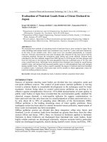
(6) PET bottle to PET bottle by mechanical recycling
39
Label
separator
①Separation of foreign substance
(color bottle, label etc.)
Label
separator
Color bottle
crasher
Label
Resource from municipality
PVC
Conveyer
Opener
Feeder
Color
Manual
separation
p
Separator
Non ferrous Second crasher
Metal remover
First crasher
②Removal of surface foreign substance by alkali
Removal of surface
Foreign substance
Vibrating
sieve
Magnetic
separator
Cap
Dehydrator
Sieve
Figure-38
Flake
Wind separator
Heater
Second
dehydrator
Rinse
PO
High level safety
①Removal of surface foreign substance by alkali
・By alkali depolymeriziation, surface PET which is contact
with food is removed.
②Removal of residue foreign substance by vacuum and
high temp. and polymerize
・Under vacuum and high temp. state, almost low molecular
organic substances are removed and a polymerization is
occurred simultaneously.
Certification of safety
・By the fraunhofer test results, FDA permitted to pass a
food contact packaging criterion.
・The regulated substances (heavy metals, chemicals) are
not detected.
Source: Kyoei industry
Process flow of flake production
Hydro
cyclone
First
dehydrator
Alkali
washer
40
10
Source: Kyoei industry
Process flow of pellet production
③Removal of residue foreign substance by vacuum and high temp. and polymerize
Vacuum, High temp.
Flake
Hopper
Polymerization and
Remove of foreign substance
Thank you for your attention.
Weight
meter
First
reactor
Figure-39
Second
reactor
Extruder
Filter
Cooling
tank
Pelletizer
Vibrating
sieve
41
Polymerization plant
Plastic Waste Management Institute
Sumitomorokko Bldg.,1-4-1 Shinkawa,Chuo-ku,Tokyo
104-0033,Japan
Tel;81-3-3297-7511 Fax;81-3-3297-7501
Web site
42
Recycled pellet
11