Ship stability for masters and mates 6th edition 2006
Bạn đang xem bản rút gọn của tài liệu. Xem và tải ngay bản đầy đủ của tài liệu tại đây (3.5 MB, 551 trang )
Ship Stability for Masters and Mates
This page intentionally left blank
Ship Stability for
Masters and Mates
Sixth edition – Consolidated 2006
Revised by Dr C.B. Barrass M.Sc C.Eng FRINA CNI
By Captain D.R. Derrett
AMSTERDAM BOSTON HEIDELBERG LONDON
NEW YORK OXFORD PARIS SAN DIEGO
SAN FRANCISCO SINGAPORE SYDNEY TOKYO
Butterworth-Heinemann
An imprint of Elsevier Ltd
Linacre House, Jordan Hill, Oxford OX2 8DP
30 Corporate Road, Burlington, MA 01803
First published by Stanford Maritime Ltd 1964
Third edition (metric) 1972
Reprinted 1973, 1975, 1977, 1979, 1982
Fourth edition 1984
Reprinted 1985
Fourth edition by Butterworth-Heinemann Ltd 1990
Reprinted 1990 (twice), 1991, 1993, 1997, 1998, 1999
Fifth edition 1999
Reprinted 2000 (twice), 2001, 2002, 2003, 2004
Sixth edition 2006
Copyright © 2006, Elsevier Ltd. All rights reserved
No part of this publication may be reproduced, stored in a retrieval system or
transmitted in any form or by any means electronic, mechanical, photocopying,
recording or otherwise without the prior written permission of the publisher
Permission may be sought directly from Elsevier’s Science & Technology Rights
Department in Oxford, UK: phone (ϩ44) (0) 1865 843830; fax (ϩ44) (0) 1865 853333;
email: Alternatively you can submit your request online by
visiting the Elsevier web site at and selecting
Obtaining permission to use Elsevier material
Notice
No responsibility is assumed by the publisher for any injury and/or damage to persons
or property as a matter of products liability, negligence or otherwise, or from any use or
operation of any methods, products, instructions or ideas contained in the material herein.
Because of rapid advances in the medical sciences, in particular, independent verification
of diagnoses and drug dosages should be made
British Library Cataloguing in Publication Data
A catalogue record for this book is available from the British Library
Library of Congress Cataloguing in Publication Data
A catalogue record for this book is available from the Library of Congress
ISBN 13: 987-0-7506-6784-5
ISBN 10: 0-7506-6784-2
For information on all Butterworth-Heinemann publications visit our
web site at www.books.elsevier.com
Typeset by Charon Tec Ltd, Chennai, India
www.charontec.com
Printed and bound in Great Britain
Contents
Acknowledgements ix
Preface xi
Introduction xiii
Part 1 Linking Ship Stability and Ship Motions
1
2
3
4
5
6
7
8
9
10
11
12
13
14
15
16
17
18
19
20
21
22
23
24
25
Forces and moments 3
Centroids and the centre of gravity 11
Density and specific gravity 21
Laws of flotation 24
Group weights, water draft, air draft and density 34
Transverse statical stability 44
Effect of free surface of liquids on stability 51
TPC and displacement curves 56
Form coefficients 62
Simpson’s Rules for areas and centroids 69
Second moments of area – moments of inertia 94
Calculating KB, BM and metacentric diagrams 103
Final KG plus twenty reasons for a rise in G 118
Angle of list 124
Moments of statical stability 134
Trim or longitudinal stability 143
Stability and hydrostatic curves 172
Increase in draft due to list 189
Water pressure 194
Combined list and trim 198
Calculating the effect of free surface of liquids (FSE) 202
Bilging and permeability 213
Dynamical stability 227
Effect of beam and freeboard on stability 233
Effects of side winds on stability 236
vi
Contents
26 Icing allowances plus effects on trim and stability 239
27 Type A, Type B and Type (B-60) vessels plus FL and PL curves
(as governed by DfT regulations) 243
28 Load lines and freeboard marks 248
29 Timber ship freeboard marks 261
30 IMO Grain Rules for the safe carriage of grain in bulk 266
31 Angle of loll 276
32 True mean draft 281
33 The inclining experiment plus fluctuations in a ship’s
lightweight 286
34 The calibration book plus soundings and ullages 293
35 Drydocking and grounding 301
36 Liquid pressure and thrust plus centres of pressure 312
37 Ship squat in open water and in confined channels 324
38 Interaction, including two case studies 337
39 Heel due to turning 353
40 Rolling, pitching and heaving motions 356
41 Synchronous rolling and parametric rolling of ships 366
42 List due to bilging side compartments 369
43 Effect of change of density on draft and trim 375
44 List with zero metacentric height 379
45 The deadweight scale 382
46 The Trim and Stability book 385
47 Simplified stability information 388
48 The stability pro-forma 394
Nomenclature of ship terms 403
Photographs of merchant ships 409
Ships of this millennium 412
Part 2 Linking Ship Stability and Ship Strength
49
50
51
52
Bending of beams 417
Bending of ships 431
Strength curves for ships 437
Bending and shear stresses 447
Part 3 Endnotes
53 Draft Surveys 467
54 Quality control plus the work of ship surveyors 470
55 Extracts from the 1998 Merchant Shipping (Load Line) Regulations
Reference Number MSN 1752 (M) 473
56 Keeping up to date 480
Contents
Part 4 Appendices
I
II
III
IV
V
Summary of stability formulae 485
SQA/MCA 2004 syllabuses for masters and mates 497
Specimen exam questions with marking scheme 505
100 Revision one-liners 516
How to pass exams in maritime studies 520
References 522
Answers to exercises 524
Index 531
vii
To my wife Hilary and our family
Acknowledgements
I gladly acknowledge with grateful thanks the help, comments and
encouragement afforded to me by the following personnel in the Maritime
Industry:
Captain D.R. Derrett, Author of ‘Ship Stability for Masters and Mates’, Third
edition (metric) 1972, published by Stanford Maritime Ltd.
Captain Sergio Battera, Vice-Chief (Retired) Pilot, Co-operation of Venice
Port and Estuary Authority.
Julian Parker, Secretariat, The Nautical Institute, London.
Tim Knaggs, Editor of the Naval Architect, Royal Institute of Naval
Architects, London.
Gary Quinn, Head of Testing Services, Scottish Qualification Authority
(SQA) Glasgow.
Roger Towner, Chief Examiner, Department for Transport/Maritime and
Coastguard Agency (DfT/MCA), Southampton.
Captain G.C. Leggett, Area Operations Manager (Surveys and Inspections),
Maritime and Coastguard Agency, Liverpool.
Captain Neil McQuaid, Chief Executive, Marcon Associates Ltd, Southport.
Malcolm Dann, Partner, Brookes Bell Jarrett Kirmann Ltd, Liverpool.
Captain I.C. Clark, Maritime Author for The Nautical Institute, London.
Darren Dodd, Managing Director, Saab Tank Control (UK), Wokingham.
Colin Jones, Stock Control Manager, DPM Ltd, Liverpool.
This page intentionally left blank
Preface
This book was written specifically to meet the needs of students studying
for their Transport Certificates of Competency for Deck Officers and
Engineering Officers, and STCW equivalent international qualifications.
Several specimen examination questions, together with a marking scheme,
have been kindly supplied by SQA/MCA.
The book will also prove to be extremely useful to Maritime Studies
degree students and serve as a quick and handy reference for Shipboard
Officers, Naval Architects, Ship Designers, Ship Classification Surveyors,
Marine Consultants, Marine Instrument Manufactures, Drydock
Personnel, Ship-owner Superintendents and Cargo-Handling Managers.
Stability can exist when a vessel is rolling or trimming – it is the ability to
remain in stable equilibrium or otherwise. Hence there is a link between
Ship Stability and Ship Motion. Stability can also exist in ship structures via
the strength of the material from which they are built. A material may be
stressed or strained and not return to its initial form, thereby losing its stability. Hence there is a link between Ship Stability and Ship Strength.
Another type of Ship Stability exists when dealing with course-headings
and course keeping. This is called Directional Stability. Examples of this are
given in Chapter 38, Interaction.
Note
Throughout this book, when dealing with Transverse Stability, BM, GM and
KM will be used. When dealing with Trim, i.e. Longitudinal Stability, then
BML , GML and KML will be used to denote the longitudinal considerations.
Therefore, there will be no suffix ‘T’ for Transverse Stability, but there
will be a suffix ‘L’ for the Longitudinal Stability text and diagrams.
C.B. Barrass
This page intentionally left blank
Introduction
In 1968, Captain D.R. Derrett wrote the highly acclaimed standard textbook
‘Ship Stability for Masters and Mates’. In 1999, for the Fifth edition, I revised
several areas of the Fourth edition (1984) book and introduced new topics
that were in keeping with examinations and developments within the shipping industry.
Changes to the Sixth edition
In 2004, the SQA/MCA made major changes to the syllabuses for the
STCW 95 Chief Mate/Master Reg. 11/2 (Unlimited) Ship Stability course.
Changes were also made to the STCW 95 Officer in Charge of Navigational
Watch Ͻ500 gt Reg. 11/3 (Near Coastal) General Ship Knowledge and Operations syllabus.
Other key changes since the Fifth (1999) edition and this Sixth edition
include the following:
●
●
●
●
●
●
●
●
●
●
●
●
●
●
●
●
●
IMO Grain Rules and angle of list
Floodable and permissible length curves
Icing allowances – effects on trim and stability
A Trim and Stability pro-forma sheet
Tabular and assigned freeboard values
Load lines and freeboard marks
Effects of side winds on stability – wind levers and wind moments
The calibration book
Update of research into squat and interaction
Air draft considerations
Draft Surveys – procedures and calculations
Synchronous rolling of ships and associated dangers
Parametric rolling of ships and associated dangers
Timber ship freeboard marks
Trimming moments about the aft perpendicular
Changes in lightweight and its KG over a period of time
Recent SQA/MCA examination questions.
xiv
Ship Stability for Masters and Mates
My main aims and objectives for this Sixth edition of the book are:
1. To help Masters, Mates and Engineering Officers prepare for their
SQA/MCA written and oral examinations.
2. To provide knowledge at a basic level for those whose responsibilities
include the loading and safe operation of ships.
3. To give Maritime students and Marine Officers an awareness of problems when dealing with stability and strength, and to suggest methods
for solving these problems if they meet them in their day-to-day operation of ships.
4. To act as a good quick reference source for those officers who obtained
their Certificates of Competency a few months/years prior to joining
their ship, port or dry-dock.
5. To help students of naval architecture/ship technology in their studies on
ONC, HNC, HND and initial years on undergraduate degree courses.
6. To assist dry-dock personnel, Ship-designers, Dft ship-surveyors,
Port Authorities, Marine Consultants, Nautical Study Lecturers, Marine
Superintendents, etc. in their Ship Stability deliberations.
There are 12 new chapters in this new edition. Also included are tabular presentations of several vessels delivered to their ship-owners in 2002–2005.
They show the typical deadweight, lengths, breadths, depths, drafts and
service speeds for 40 ships. These parameters give a good awareness of just
how large and how fast merchant ships can be. Photographs of ships have
been added to this edition.
Another addition to the 1999 edition is the nomenclature or glossary of
ship terms. This will prove useful for the purpose of rapid consultation.
The revision one-liners have been extended by 35 questions to bring the
final total to 100. A case study, involving squat, interaction and the actual
collision of two vessels is analysed in detail.
The discourse on how to pass Maritime exams has now been modified and
expanded. A selection of SQA/MCA exam questions set recently, together
with a marking scheme, has been incorporated into this new edition.
Maritime courts are continually dealing with ships that have grounded,
collided or capsized. If this book helps to prevent further incidents of this
sort, then the efforts of Captain D.R. Derrett and myself will have been
worthwhile.
Finally, it only remains for me to wish the student every success in
the exams, and to wish those working within the shipping industry continued success in your chosen career. I hope this book will be of interest and
assistance.
C.B. Barrass
Part 1
Linking Ship
Stability and Ship
Motions
This page intentionally left blank
Chapter 1
Forces and
moments
The solution of many of the problems concerned with ship stability involves
an understanding of the resolution of forces and moments. For this reason a
brief examination of the basic principles will be advisable.
Forces
A force can be defined as any push or pull exerted on a body. The S.I. unit of
force is the Newton, one Newton being the force required to produce in a
mass of one kilogram an acceleration of one metre per second. When considering a force the following points regarding the force must be known:
(a) The magnitude of the force.
(b) The direction in which the force is applied.
(c) The point at which the force is applied.
The resultant force. When two or more forces are acting at a point, their
combined effect can be represented by one force which will have the same
effect as the component forces. Such a force is referred to as the ‘resultant
force’, and the process of finding it is called the ‘resolution of the component forces’.
The resolution of forces. When resolving forces it will be appreciated that a
force acting towards a point will have the same effect as an equal force acting away from the point, so long as both forces act in the same direction and
in the same straight line. Thus a force of 10 Newtons (N) pushing to the
right on a certain point can be substituted for a force of 10 Newtons (N)
pulling to the right from the same point.
(a) Resolving two forces which act in the same straight line
If both forces act in the same straight line and in the same direction the
resultant is their sum, but if the forces act in opposite directions the resultant is the difference of the two forces and acts in the direction of the larger
of the two forces.
4
Ship Stability for Masters and Mates
Example 1
Whilst moving an object one man pulls on it with a force of 200 Newtons, and
another pushes in the same direction with a force of 300 Newtons. Find the
resultant force propelling the object.
Component forces 300 N A 200 N
>.
>
The resultant force is obviously 500 Newtons, the sum of the two forces,
and acts in the direction of each of the component forces.
Resultant force 500 N A or A 500 N
.
>>
.
>>
Example 2
A force of 5 Newtons is applied towards a point whilst a force of 2 Newtons
is applied at the same point but in the opposite direction. Find the resultant
force.
Component forces 5 N A 2 N
>
. <
Since the forces are applied in opposite directions, the magnitude of the
resultant is the difference of the two forces and acts in the direction of the 5 N
force.
Resultant force 3 N
A or A 3 N
>> .
. >>
(b) Resolving two forces which do not act in the same straight line
When the two forces do not act in the same straight line, their resultant can
be found by completing a parallelogram of forces.
Example 1
A force of 3 Newtons and a force of 5 N act towards a point at an angle of
120 degrees to each other. Find the direction and magnitude of the resultant.
nt
a
ult
s
Re
3N
120°
A
5N
Fig. 1.1
1
Ans. Resultant 4.36 N at 36º 34 –2 Ј to the 5 N force.
Note. Notice that each of the component forces and the resultant all act towards
the point A.
Forces and moments
9 knots
A
B
Resultant
3 knots
D
C
Fig. 1.2
Example 2
A ship steams due east for an hour at 9 knots through a current which sets
120 degrees (T) at 3 knots. Find the course and distance made good.
The ship’s force would propel her from A to B in one hour and the current
1
would propel her from A to C in one hour. The resultant is AD, 0.97 –2 º ϫ 11.6
miles and this will represent the course and distance made good in one hour.
Note. In the above example both of the component forces and the resultant
force all act away from the point A.
Example 3
A force of 3 N acts downwards towards a point whilst another force of 5 N acts
away from the point to the right as shown in Figure 1.3. Find the resultant.
3N
A
5N
Fig. 1.3
In this example one force is acting towards the point and the second force
is acting away from the point. Before completing the parallelogram, substitute either a force of 3 N acting away from the point for the force of 3 N
towards the point as shown in Figure 1.4, or a force of 5 N towards the point
3N
5N
A
Re
3N
su
lta
Fig. 1.4
nt
5
6
Ship Stability for Masters and Mates
Re
su
lta
3N
nt
5N
A
5N
Fig. 1.5
for the force of 5 N away from the point as shown in Figure 1.5. In this way
both of the forces act either towards or away from the point. The magnitude
and direction of the resultant is the same whichever substitution is made;
i.e. 5.83 N at an angle of 59° to the vertical.
(c) Resolving two forces which act in parallel directions
When two forces act in parallel directions, their combined effect can be
represented by one force whose magnitude is equal to the algebraic sum of
the two component forces, and which will act through a point about which
their moments are equal.
The following two examples may help to make this clear.
Example 1
In Figure 1.6 the parallel forces W and P are acting upwards through A and B
respectively. Let W be greater than P. Their resultant (W ϩ P) acts upwards
through the point C such that P ϫ y ϭ W ϫ x. Since W is greater than P, the
point C will be nearer to B than to A.
P
WϩP
A
W
C
y
B
x
Fig. 1.6
Example 2
In Figure 1.7 the parallel forces W and P act in opposite directions through
A and B respectively. If W is again greater than P, their resultant (W Ϫ P) acts
through point C on AB produced such that P ϫ y ϭ W ϫ x.
Forces and moments
7
P
A
B
C
y
x
W
W–P
Fig. 1.7
Moments of forces
The moment of a force is a measure of the turning effect of the force about a
point. The turning effect will depend upon the following:
(a) The magnitude of the force.
(b) The length of the lever upon which the force acts, the lever being the
perpendicular distance between the line of action of the force and the
point about which the moment is being taken.
The magnitude of the moment is the product of the force and the length of
the lever. Thus, if the force is measured in Newtons and the length of the lever
in metres, the moment found will be expressed in Newton-metres (Nm).
Resultant moment. When two or more forces are acting about a point their
combined effect can be represented by one imaginary moment called the
‘Resultant Moment’. The process of finding the resultant moment is referred
to as the ‘Resolution of the Component Moments’.
Resolution of moments. To calculate the resultant moment about a point,
find the sum of the moments to produce rotation in a clockwise direction
about the point, and the sum of the moments to produce rotation in an anticlockwise direction. Take the lesser of these two moments from the greater
and the difference will be the magnitude of the resultant. The direction in
which it acts will be that of the greater of the two component moments.
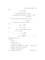
Example 1
A capstan consists of a drum 2 metres in diameter around which a rope is
wound, and four levers at right angles to each other, each being 2 metres long.
If a man on the end of each lever pushes with a force of 500 Newtons, what
strain is put on the rope? (See Figure 1.8(a).)
Moments are taken about O, the centre of the drum.
Total moment in an anti-clockwise direction ϭ
The resultant moment ϭ
Let the strain on the rope ϭ
The moment about O ϭ
І Pϫ1ϭ
or P ϭ
Ans. The strain is 4000 N.
4 ϫ (2 ϫ 500) Nm
4000 Nm (Anti-clockwise)
P Newtons
(P ϫ 1) Nm
4000
4000 N
8
Ship Stability for Masters and Mates
Note. For a body to remain at rest, the resultant force acting on the body must
be zero and the resultant moment about its centre of gravity must also be
zero, if the centre of gravity be considered a fixed point.
500 N
2m
‘P’ N
500 N
2m
O
2m
500 N
1m
2m
500 N
Fig. 1.8(a)
Mass
In the S.I. system of units it is most important to distinguish between the
mass of a body and its weight. Mass is the fundamental measure of the
quantity of matter in a body and is expressed in terms of the kilogram and
the tonne, whilst the weight of a body is the force exerted on it by the
Earth’s gravitational force and is measured in terms of the Newton (N) and
kilo-Newton (kN).
Weight and mass are connected by the formula:
Weight ϭ Mass ϫ Acceleration
Example 2
Find the weight of a body of mass 50 kilograms at a place where the acceleration due to gravity is 9.81 metres per second per second.
Weight ϭ Mass ϫ Acceleration
ϭ 50 ϫ 9.81
Ans. Weight ϭ 490.5 N
Forces and moments
9
Moments of mass
If the force of gravity is considered constant then the weight of bodies is proportional to their mass and the resultant moment of two or more weights
about a point can be expressed in terms of their mass moments.
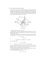
Example 3
A uniform plank is 3 metres long and is supported at a point under its midlength. A load having a mass of 10 kilograms is placed at a distance of
0.5 metres from one end and a second load of mass 30 kilograms is placed
at a distance of one metre from the other end. Find the resultant moment
about the middle of the plank.
3m
0.5 m
1m
0.5 m
1m
O
10 kg
30 kg
Fig. 1.8(b)
Moments are taken about O, the middle of the plank.
Clockwise moment ϭ
ϭ
Anti-clockwise moment ϭ
ϭ
Resultant moment ϭ
Ans. Resultant moment ϭ 5 kg m clockwise
30 ϫ 0.5
15 kg m
10 ϫ 1
10 kg m
15 Ϫ 10

![ship stability for masters and mates [electronic resource]](https://media.store123doc.com/images/document/14/y/bj/medium_bjc1401370968.jpg)