Seismic performance of wind designed diagrid tall steel buildings in regions of moderate seismicity and strong wind
Bạn đang xem bản rút gọn của tài liệu. Xem và tải ngay bản đầy đủ của tài liệu tại đây (1.01 MB, 17 trang )
Steel and Composite Structures, Vol.14, No. 2 (2013) 155-171
155
DOI: />
Seismic Performance of Wind-Designed Diagrid Tall Steel
Buildings in Regions of Moderate Seismicity and Strong Wind
1
2
Seonwoong Kim and Kyungkoo Lee*
1
2
Disaster Prevention Research Team, DAEWOO E&C, Suwon, Korea
Dept. of Architectural Engineering, Dankook University, Yongin, Korea
(Received March 14, 2012, Revised December 26, 2012, Accepted January 19, 2013)
Abstract. This study analytically evaluated the seismic performance of wind-designed diagrid tall steel
buildings in regions of moderate/low seismicity and strong winds. To this end, diagrid tall steel buildings
with varying wind exposure and slenderness ratio (building height-to-width ratio) conditions were designed
to satisfy the wind serviceability criteria specified in the Korean Building Code and the National Building
Code of Canada. A series of seismic analyses were then performed for earthquakes having 43- and 2475year return periods utilizing the design guidelines of tall buildings. The analyses demonstrated the good
seismic performance of these wind-designed diagrid tall steel buildings, which arises because significant
overstrength of the diagrid system occurs in the wind design procedure. Also, analysis showed that the
elastic seismic design process of diagrid tall steel buildings might be accepted based on some wind
exposures and slenderness ratios.
Keywords: moderate/low seismicity; tall steel buildings; diagrid; wind design; seismic performance
1. Introduction
As specifications for seismic design have become mandatory in building design codes, there
has been controversy over the direction for seismic design of tall buildings in moderate/low
seismicity regions. The study of seismic design of tall buildings in high seismicity regions was not
even actively implemented until the advent of the 2000’s. Representative seismic design guidelines
for tall buildings have been suggested by the Los Angeles Tall Buildings Structural Design Council
(LATBSDC 2005,2008), the Council on Tall Buildings and Urban Habitat (CTBUH 2008), and the
Pacific Earthquake Engineering Research Center (PEER 2010) of the US. And many studies on the
alternative design procedure for tall buildings and ground motions for design of tall buildings in
high seismicity regions have been done (Moehle 2007, Lew et al. 2008). Seismic design procedure
for tall buildings in moderate/low seismicity regions only changed some requirements in the
alternative design procedure for tall buildings in high seismicity regions (Kelly and Zona 2006).
However, the design provision for tall buildings in high seismicity regions can be too conservative
for tall buildings in low to moderate seismicity regions because of the reduced seismic demand
(Ho 2011). Until recently, no seismic design method for tall buildings in moderate/low seismicity
*
Corresponding author, Ph.D., E-mail:
156
Seonwoong Kim and Kyungkoo Lee
regions has been agreed with any reasonable consensus.
The Korean peninsula is located in a region of strong wind that frequently experiences
typhoons during the summer season. So far, the maximum instantaneous wind speed observed in
the Korean peninsula is 63.7 m/sec, in October, 2010. Typhoons are usually classified into four
grades; the lower bound of the maximum wind speed of the strongest typhoon is 44 m/sec. On the
other hand, the earthquake hazard level in the Korean peninsula is of low seismicity, having an
effective peak ground acceleration of 0.147g, which corresponds to two-thirds of ground motion
with a 2475-year return period. The other regions of the world, such as the southeast regions of the
United States, Australia, and Hong Kong, fit into the same conditions of strong wind and
moderate/low seismicity. In these regions, the magnitude of seismic load applied to tall buildings
is relatively smaller than the magnitude of wind load. Therefore, in practice, it is common to skip
or simplify the evaluation of seismic performance of tall buildings, assuming the satisfactory
inelastic behavior of the structural system under seismic load. However, the structural system
applied to tall buildings is the so-called undefined system; here the problem is that it is not easy to
classify the system by structural type defined in the current seismic design code, which is not
appropriate for tall buildings.
Globally, there has been an increasing trend of demand for tall buildings as a symbol of landuse efficiency, and as landmarks of the particular country. So in South Korea, where many tall
buildings are being constructed or planned. Recently, the shape of tall buildings has developed
from a simple cubic form to a freeform. As a way to actively respond to the change in shape of
buildings, many structural engineers have adopted the diagrid structural system, which can
effectively resist both vertical and horizontal load through using only diagonal elements.
The diagrid structural system is a kind of concentrically-braced frame. In general,
concentrically-braced steel frames have been considered as a relatively brittle system, because
redistribution of forces during inelastic behavior is not expected due to low redundancy and soft
story response which occurs when inelastic deformation accumulates on the buckled story after
braces buckle (Tremblay 2002). Lee and Kim (2007) argued that it is desirable to limit the
behavior of tall concentrically-braced steel systems in the elastic range, even under very rare
ground motion. They proposed an elastic seismic design procedure for tall concentrically-braced
steel frames in regions of strong wind and moderate seismicity, such as the Korean peninsula. Tall
buildings are designed to be structures with significant system overstrength, in order to secure the
serviceability required in the wind design process. In particular, in the case of steel frame buildings
having a small self-weight, the effect of wind load on building increases and the effect of seismic
load decreases as the slenderness ratio (height-to-width ratio) of the building increases. As a result,
the base shear due to the wind may become close to the elastic base shear due to earthquakes for
tall steel buildings in regions of strong wind and moderate/low seismicity. In other word, most
primary structural members of wind-designed tall steel buildings in certain conditions may remain
elastic under earthquake ground motion not considering response modification factor. Thus, the
elastic seismic design of tall steel buildings in this region could be economically acceptable.
Taking into consideration these matters, this study assessed the seismic performance of winddesigned diagrid tall steel buildings in regions of moderate/low seismicity and strong wind. First,
diagrid tall steel buildings with three different slenderness ratios were designed according to wind
design criteria under differing wind exposure. Then, the seismic performance of the buildings was
evaluated by conducting linear dynamic analysis using response spectrum method. Finally, the
possibility of elastic seismic design of the buildings was assessed.
Seismic Performance of Wind-Designed Diagrid Tall Steel Buildings
157
2. Wind Design of Steel-Framed Diagrid Structures for Tall Buildings
For seismic case studies, steel-framed diagrid structures for hypothetical tall buildings were
designed by utilizing wind load design conditions, as indicated in Table 1. The buildings were
assumed to be located in Seoul, South Korea, with various wind exposures. A basic wind speed of
30m/sec, topographic factor of 1.0, and importance factor of 1.1 were adopted from the Korean
Building Code (2009). The approximate expression of the Architectural Institute of Japan (2004),
introduced into the Korean Building Code (2009), was used for the first natural frequency (no) of
building and the first damping coefficient (ζf) of building in the wind direction. A dead load of 4.6
kN/m2 and live load of 2.5 kN/m2 were applied to the buildings, respectively. The steel diagrid
Table 1Factors for wind load calculation
Factors
Basic wind speed (Vo)
Value
30 m/sec
Topographic factor
1.0
Importance factor (Iw)
1.1
First natural frequency (no) of a
building
First damping ratio of a building in
wind direction
0.2003
0.0026
Remark
Seoul
Flat regions no affected by
mountains, hills and inclined
ground
above 35 stories, 100 m, or
slenderness of 5
1/0.02H (steel frame: slenderness of
6.9)
0.013no (steel frame: slenderness
ratio of 6.9)
G3
Tier 7
Tier 6
Tier 5
G1
G2
Tier 4
Tier 3
G4
Tier 2
Tier 1
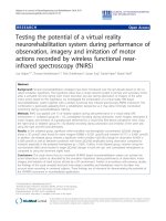
(a) Elevation view
(b) Plan view
Fig. 1 Elevation and plan view of diagrid system (slenderness ratio = 6.1)
158
Seonwoong Kim and Kyungkoo Lee
system was designed by the limit state design method (AISC 2005), to ensure that the slenderness
ratio (the ratio of building height (H) to building width (d)) was within the range of 5.2 (187.2 m,
48 stories) ∼ 6.9 (249.6 m, 64 stories), considering the capacity limit for the thickness of steel
plate, which aimed at examining the behavorial characteristics of diagrid tall steel buildings
corresponding to the change in level of wind exposure (see Fig. 1). The slenderness ratio related to
the angle of diagonals is also very critical for the optimal design of diagonals (Zhang et al. 2012).
In the diagrid frame system, the diagonal members resist both the gravity force and the lateral
force, without vertical columns. Lateral force is resisted by the web frame of the building, which is
parallel to the lateral force, and the flange frame of the building, which is perpendicular to the
lateral force, as shown in Fig. 1.
That is, the web frame resists shear force, and the flange frame resists overturning moment. For
reference purposes, Moon et al. (2007) conducted a study of variables for steel quantity reduction
in the wind design process of the diagrid steel frame system, and stated that as limit conditions for
optimal design the slenderness ratio should be no less than 5, and the tilt angle of diagonal member
from the vertical axis (θ) should be in the range of 60°∼70°. In addition, they suggested that the
wind resisting performance of the diagrid structure is optimal when the tilt angle of diagonal
member is 69°. Based on such suggestions, a diagrid frame system of eight stories was designed as
one tier in this study, ensuring that the tilt angle of the diagonal member was approximately 69°.
The built-up rectangular steel tubes were used for exterior diagonal members and interior gravity
columns. The cross-sectional areas of diagonal members in flange frame and web frame were
calculated by using Eq. (1) and Eq. (2), respectively (Moon et al. 2007 ).
Ad , f
N
Ad , w
d, f
2MLd
d w2 Ed *h sin 2
VLd
2 N d , w Ed *h cos 2
for flange frame
(1)
for web frame
(2)
where Ed is the elasticity modulus of the diagonal member, h is the height of a tier, Ld is the
length of the diagonal member, M is the overturning moment of a tier, Nd,f is the number of
diagonal members in the flange frame, Nd,w is the number of diagonal members in the web frame, s
is the ratio of roof story displacement due to shear force to roof story displacement due to
overturning moment (= H/d-3), V is the shear force at a tier, is the limit variable of roof story
displacement for wind-resistant serviceability design (= 500 in this study), γ* is 1/[(1+s)α], δd is the
contribution of web frame to flexural stiffness (= 2 in general), and χ* is (2γ*s)/H. For more details,
kindly refer to the references (Moon et al. 2007).
Steel H-shapes (wide flange shapes) were used for girders and beams. All connections were
assumed as simple connections to minimize connection cost. The dimensions of diagonals,
columns and beams are listed in Table 2. The material properties of steel used in diagonal
members and interior gravity columns followed the nominal values for SM 490 steel, with yield
strengths (Fy) of 325 MPa (for plate thickness equal to or less than 40mm) or 295 MPa (for plate
thicker than 40mm, but less than 100mm), and tensile strength (Fu) of 490 MPa. The material
properties of steel used in girders and beams followed the nominal values for SS 400 steel, with
yield strengths of 235 MPa (for plate thickness equal to or less than 40mm) or 215 MPa (for plate
thicker than 40mm, but less than 100mm), and tensile strength of 400 MPa. An elastic modulus of
2.05x10⁵MPa was used for all steel members.
Seismic Performance of Wind-Designed Diagrid Tall Steel Buildings
159
Table 2 Size of main structural members
(a) Diagonal members
Exposure
Slenderness
5.2
6.1
A
6.9
5.2
6.1
B
6.9
Exposure
Tier
6
5
4
3
2
1
7
6
5
4
3
2
1
8
7
6
5
4
3
2
1
6
5
4
3
2
1
7
6
5
4
3
2
1
8
7
6
5
4
3
2
1
SlenderTier
ness
Required area (cm2)
Web
192.17
382.54
556.66
712.89
848.61
962.12
284.13
568.94
833.69
1,076.82
1,296.15
1,488.21
1,650.72
393.48
791.27
1,165.20
1,513.76
1,835.01
2,126.16
2,382.85
2,602.18
241.14
485.81
715.81
928.63
1,119.92
1,282.04
344.67
697.19
1,032.46
1,348.20
1,641.06
1,905.24
2,130.58
463.42
940.17
1,397.17
1,832.34
2,242.80
2,624.32
2,969.55
3,265.64
Flange
46.85
182.92
401.10
693.64
1,051.81
1,465.51
57.90
226.88
499.56
868.02
1,323.61
1,856.65
2,455.87
71.36
280.42
619.30
1,079.68
1,652.62
2,328.41
3,096.12
3,943.08
58.31
230.61
509.73
888.73
1,358.33
1,908.26
70.04
276.31
612.54
1,071.75
1,645.85
2,325.07
3,096.29
83.85
331.40
736.23
1,291.30
1,988.70
2,819.35
3,772.20
4,832.48
Required area
(cm2)
Web
Flange
Section
Width –
to-Thk.
Designed
area (cm2)
□-300×300×17
□-425×425×24
□-510×510×29
□-575×575×33
□-700×700×40
□-845×845×46
□-360×360×21
□-520×520×29
□-615×615×36
□-715×715×40
□-800×800×44
□-945×945×52
□-1,100×1,100×59
□-420×420×25
□-605×605×35
□-755×755×41
□-855×855×47
□-955×955×51
□-1,065×1,065×58
□-1,240×1,240×66
□-1,390×1,390×75
□-345×345×20
□-480×480×27
□-580×580×33
□-665×665×37
□-820×820×44
□-970×970×52
□-400×400×23
□-565×565×33
□-690×690×40
□-815×815×44
□-890×890×49
□-1,065×1,065×58
□-1,240×1,240×66
□-460×460×27
□-660×660×38
□-825×825×45
□-950×950×51
□-,045×1,045×57
□-1,185×1,185×63
□-1,365×1,365×73
□-1,540×1,540×83
15.65
15.71
15.59
15.42
15.50
16.37
15.14
15.93
15.08
15.88
16.18
16.17
16.64
14.80
15.29
16.41
16.19
16.73
16.36
16.79
16.53
15.25
15.78
15.58
15.97
16.64
16.65
15.39
15.12
15.25
16.52
16.16
16.36
16.79
15.04
15.37
16.33
16.63
16.33
16.81
16.70
16.55
192.44
384.96
557.96
715.44
1,056.00
1,470.16
284.76
569.56
833.76
1,080.00
1,330.56
1,857.44
2,456.76
395.00
798.00
1,170.96
1,519.04
1,844.16
2,336.24
3,099.36
3,945.00
260.00
489.24
722.04
929.44
1,365.76
1,909.44
346.84
702.24
1,040.00
1,356.96
1,648.36
2,336.24
3,099.36
467.64
945.44
1,404.00
1,833.96
2,252.64
2,827.44
3,772.64
4,837.24
Section
Width – Designed
to-Thk. area (cm2)
Strength increase
(%)
Web
Flange
0.14
310.75
0.63
110.45
0.23
39.11
0.36
3.14
24.44
0.40
52.80
0.32
0.22
391.85
0.11
151.04
0.01
66.90
0.30
24.42
2.65
0.52
24.81
0.04
48.83
0.04
0.39
453.49
0.85
184.57
0.49
89.08
0.35
40.69
0.50
11.59
9.88
0.34
30.07
0.10
51.60
0.05
7.82
343.63
0.71
112.15
0.87
41.65
0.09
4.58
21.95
0.51
48.94
0.06
0.63
395.19
0.72
154.15
0.73
69.78
0.65
26.61
0.44
0.15
22.62
0.48
45.47
0.10
0.91
457.69
0.56
185.28
0.49
90.70
0.09
42.02
0.44
13.27
7.74
0.29
27.04
0.01
48.13
0.10
Strength increase
(%)
Web Flange
160
Seonwoong Kim and Kyungkoo Lee
5.2
6.1
C
6.9
5.2
6.1
D
6.9
6
5
4
3
2
1
7
6
5
4
3
2
1
8
7
6
5
4
3
2
1
6
5
4
3
2
1
7
6
5
4
3
2
1
8
7
6
5
4
3
2
1
278.35
565.21
839.95
1,099.93
1,340.30
1,549.04
389.19
792.51
1,182.01
1,555.38
1,909.07
2,236.64
2,522.06
513.41
1,047.61
1,566.39
2,067.67
2,548.53
3,004.50
3,427.40
3,796.96
303.07
618.94
925.73
1,221.09
1,500.66
1,751.10
417.23
853.74
1,280.09
1,694.31
2,093.31
2,471.25
2,810.37
543.11
1,112.86
1,671.47
2,217.20
2,747.59
3,258.71
3,743.15
4,178.44
67.51
267.01
593.39
1,040.52
1,600.63
2,262.16
78.95
312.81
696.62
1,224.68
1,890.17
2,684.40
3,594.52
92.76
367.98
820.70
1,445.34
2,235.46
3,183.37
4,279.29
5,508.69
73.40
291.38
650.12
1,144.97
1,769.77
2,514.69
84.54
335.98
750.73
1,324.53
2,052.18
2,926.80
3,937.45
98.02
389.91
872.10
1,540.53
2,390.40
3,415.84
4,609.09
5,957.80
□-355×355×21
□-520×520×29
□-620×620×36
□-715×715×41
□-885×885×48
□-1,050×1,050×57
□-430×430×24
□-605×605×35
□-765×765×41
□-875×875×47
□-970×970×52
□-1,145×1,145×62
□-1,325×1,325×72
□-490×490×28
□-695×695×40
□-885×885×47
□-1,015×1,015×54
□-1,125×1,125×60
□-1,255×1,255×67
□-1,450×1,450×78
□-1,655×1,655×88
□-370×370×22
□-535×535×31
□-665×665×37
□-770×770×42
□-935×935×50
□-1,110×1,110×60
□-445×445×25
□-630×630×36
□-790×790×43
□-915×915×49
□-1,010×1,010×55
□-1,195×1,195×65
□-1,390×1,390×75
□-500×500×29
□-720×720×41
□-905×905×49
□-1,050×1,050×56
□-1,170×1,170×62
□-1,310×1,310×70
□-1,505×1,505×81
□-1,715×1,715×92
14.90
15.93
15.22
15.44
16.44
16.42
15.92
15.29
16.66
16.62
16.65
16.47
16.40
15.50
15.38
16.83
16.80
16.75
16.73
16.59
16.81
14.82
15.26
15.97
16.33
16.70
16.50
15.80
15.50
16.37
16.67
16.36
16.38
16.53
15.24
15.56
16.47
16.75
16.87
16.71
16.58
16.64
280.56
569.56
840.96
1,105.36
1,607.04
2,264.04
389.76
798.00
1,187.36
1,556.64
1,909.44
2,685.84
3,608.64
517.44
1,048.00
1,575.44
2,075.76
2,556.00
3,183.84
4,280.64
5,515.84
306.24
624.96
929.44
1,223.04
1,770.00
2,520.00
420.00
855.36
1,284.84
1,697.36
2,101.00
2,938.00
3,945.00
546.36
1,113.56
1,677.76
2,226.56
2,747.84
3,425.16
4,613.76
5,972.64
0.79
0.77
0.12
0.49
19.90
46.16
0.15
0.69
0.45
0.08
0.02
20.08
43.08
0.79
0.04
0.58
0.39
0.29
5.97
24.89
45.27
1.05
0.97
0.40
0.16
17.95
43.91
0.66
0.19
0.37
0.18
0.37
18.89
40.37
0.60
0.06
0.38
0.42
0.01
6.55
23.26
42.94
315.56
113.31
41.72
6.23
0.40
0.08
393.66
155.11
70.45
27.11
1.02
0.05
0.39
457.83
184.80
91.96
43.62
14.34
0.01
0.03
0.13
317.22
114.49
42.96
6.82
0.01
0.21
396.83
154.58
71.15
28.15
2.38
0.38
0.19
457.41
185.60
92.38
44.53
14.95
1.64
0.10
0.25
(b) Girders, beams, and gravity columns
Slenderness
Member
5.2 ~ 6.9
G1
G2
G3
G4
Gravity column
Section
(beam depth×beam width×web thickness×flange
thickness)
H-900×300×16×28
H-506×201×11×19
H-890×299×15×23
H-340×250×9×14
□-455×455×27 ~ □-1340×1340×71
Seismic Performance of Wind-Designed Diagrid Tall Steel Buildings
161
The roof story displacement, which is the serviceability requirement against wind load, was
limited to be less than 1/500 of the building height in the process of calculating the cross-sectional
area of diagonal members in Eq. (1) and Eq. (2) (see Table 3). The width-to-thickness ratio of the
sections of diagonal members was also limited to satisfy seismic design criteria (AISC, 2005).
Then, as shown in the 4th and 5th columns (area of web and flange frame) of Table 2 (a), the
required total cross-sectional areas of diagonal members in web and flange frame at each tier were
respectively determined. Consequently, considering an arbitrary wind direction, the sectional size
of the diagonal members in both web frame and flange frame should be designed to be identical. In
other words, the resulting cross-sectional areas of designed diagonal members at each tier were
calculated as listed in the 8th column (designed section) of Table 2(a). It should be noted that the
size of diagonal members tends to increase significantly, especially in the upper part of the flange
frame of buildings. These overstrength factors are expected to make it possible that the diagrid tall
steel buildings may behave elastically under moderate or weak earthquake. Table 4 summarized
the model base shears induced by wind and seismic loads. The values indicate the possibility of
elastic behavior of the wind-designed buildings subjected to such moderate or weak earthquake.
As wind-induced vibration of a building causes unpleasant feelings for building residents, it is
generally a requirement in the process of wind design to investigate wind-induced vibration
acceleration of the building (AIK, 2009; NBCC, 2005). According to the National Building Code
of Canada (2005), the building should be checked for design wind load and its effect by
performing static analysis, dynamic analysis, or wind-tunnel test. Static procedure targets most
mid-rise and low-rise buildings, and dynamic procedure targets tall buildings of a height of 120 m
or higher, as well as slender buildings. Since the buildings considered in this study stand more than
120 m high, the dynamic procedure was applied to calculate the vibration accelerations of the
buildings in both the along-wind and the across-wind directions. As suggested by NBCC (2005), a
one-hour average wind speed with a return period of 10 years was used as follows:
Wind-induced vibration acceleration in the along-wind direction
aD 4 2 f nD2 g p
KsF
CeH D C g
(3)
Wind-induced vibration acceleration in the across-wind direction
ar
2
aw f nW
g p wd
g
W
B
3.3
(4)
where ar is 78.5×10³ VH / f nW wd (N/m3), CeH is the height distribution coefficient of wind
speed according to exposure classification, Cg is the dynamic gust factor, F is the gust energy ratio,
g is the acceleration of gravity (= 9.81 m/s2), gp is the peak factor, K is the surface roughness
coefficient of the terrain, fnD is the fundamental natural frequency in the along-wind direction, fnW
is the fundamental natural frequency in the across-wind direction, s is the size reduction factor
162
Seonwoong Kim and Kyungkoo Lee
Web
Flange
Slenderness 5.2
Web
Flange
Slenderness 6.1
(a) SLE
Web
Flange
Slenderness 6.9
Web
Flange
Slenderness 5.2
Web
Flange
Web
Flange
Slenderness 6.1
Slenderness 6.9
(b) MCE
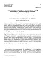
Fig. 2 DCR distribution from response spectrum analysis (Exposure A) (━: elastic member, …: inelastic
member)
according to the aspect ratio of the building, w is the width of building in the across-wind direction
(m), βD is the critical damping fraction in the along-wind direction, βW is the critical damping
fraction in the across-wind direction, ρB is the average density of the building (= 120.3 kg/m3), and
Δ is the maximum wind-induced lateral displacement at the top of the building in the along-wind
direction (m).
The wind speed with a return period of 10 years, VH, which is required to calculate the windinduced acceleration, was obtained by utilizing the Gumbel statistics distribution equation (KBC,
2009) as follows, based on data provided by the Korea Meteorological Administration.
1 T
V(T ) ln ln
b
a T 1
(5)
163
Seismic Performance of Wind-Designed Diagrid Tall Steel Buildings
Web
Flange
Slenderness 5.2
Web
Flange
Slenderness 6.1
(a) SLE
Web
Flange
Slenderness 6.9
Web
Flange
Slenderness 5.2
Web
Flange
Web
Flange
Slenderness 6.1
Slenderness 6.9
(b) MCE
Fig. 3 DCR distribution from response spectrum analysis (Exposure B) (━: elastic member, …: inelastic
member)
Table 3 Roof displacement check
Slenderness
5.2
6.1
6.9
Exposure A
29.10 cm
34.40 cm
39.59 cm
MIDAS Gen
Exposure B
Exposure C
28.43 cm
28.64 cm
33.74 cm
33.93 cm
38.96 cm
39.13 cm
Exposure D
28.54 cm
33.74 cm
38.99 cm
Limit
(H/500)
37.44 cm
43.68 cm
49.92 cm
164
Seonwoong Kim and Kyungkoo Lee
where, a (= 0.42) and b (= 14.32) are characteristic values of the Gumbel extreme value
distribution in Seoul, V(T) is the wind speed with a return period of T years, and T is the time (year).
Generally, in the case of tall buildings [usually in the case of (wd)1/2/H ≤ 1/3], it is known that
wind-induced vibration in the across-wind direction causes a greater problem to serviceability than
wind-induced vibration in the along-wind direction. When a preliminary assessment of tall
buildings is conducted, the wind-induced vibration acceleration due to wind speed with a return
period of 10 years generally lies in the range of 1∼3% of the acceleration of gravity. For example,
most tall buildings constructed in North America from 1975 to 2000 were designed to have windinduced vibration acceleration within the range of 1.5∼2.5% of the acceleration of gravity,
through the result of wind-tunnel tests (NBCC, 2005). In general, the lower limit value in this
range is applied to residential buildings, while the upper limit value is applied to office buildings.
In addition, KBC (2009) classifies the wind exposure to four levels (A, B, C, and D), whereas
NBCC (2005) classifies the wind exposure to three levels (A, B and C). The wind exposures A and
B in KBC correspond to the wind exposure C in NBCC, the wind exposure C in KBC corresponds
to the wind exposure B in NBCC, and the wind exposure D in KBC corresponds to the wind
exposure A in NBCC, respectively. As shown in Table 5, it is confirmed that the diagrid frame
system designed in this study satisfied all serviceability criteria (i.e. 30 gal or less for an office
building) against wind-induced vibration accelerations in both the along-wind direction and the
across-wind direction.
3. Seismic Performance Evaluation Based on Linear Dynamic Procedure
In this section, the seismic performance of diagrid tall steel buildings designed in the previous
section was evaluated and the possibility of elastic response of diagonal members was checked by
conducting linear dynamic analysis using response spectrum method.
Table 4 Comparisons of model base shears from wind and seismic loads
Slenderness
Exposure A
17,731.4
23,938.7
31,107.3
5.2
6.1
6.9
Wind load (kN)
Exposure B
Exposure C
23,627.5
28,548.2
30,897.6
36,574.9
39,038.6
45,390.2
Exposure D
32,272.1
40,755.9
49,950.5
Seismic load
(kN)
18,838.4
19,578.2
20,244.5
Table 5 Wind-induced vibration acceleration check per NBCC 2005
Exposure
KBC 2009
NBCC 2005
A, B
C
C
B
D
A
Wind direction
Along-wind
Across-wind
Along-wind
Across-wind
Along-wind
Across-wind
Vibration acceleration (gal)
Slenderness
5.2
6.1
1.50
2.07
1.70
2.73
1.71
2.25
2.64
4.00
1.86
2.35
3.55
5.05
Limit
6.9
2.71
4.11
2.84
5.70
2.86
6.84
30 for
office
building
Seismic Performance of Wind-Designed Diagrid Tall Steel Buildings
Web
Flange
Slenderness 5.2
Web
Flange
Slenderness 6.1
(a) SLE
165
Web
Flange
Slenderness 6.9
Web
Flange
Slenderness 5.2
Web
Flange
Web
Flange
Slenderness 6.1
Slenderness 6.9
(b) MCE
Fig. 4 DCR distribution from response spectrum analysis (Exposure C) (━: elastic member, …: inelastic
member)
First, with regard to seismic performance evaluation, it shall be noted that the current tall
building design guidelines, such as CTBUH (2008), LATBSDC (2008), and TBI (PEER 2010), do
not suggest the standard procedure to evaluate the seismic performance of mega structural
members in tall buildings, and recommend following the procedure in ASCE 41-06 (2007).
Therefore, this paper adopted hazard levels and target building performance levels by tall building
design guidelines and followed evaluation procedure by ASCE 41-06 (2007).
CTBUH (2008), LATBSDC (2008), and TBI (PEER 2010), which are the latest seismic design
guidelines for tall buildings, define two basic earthquake hazard levels: service level earthquake
(SLE) and maximum considered earthquake (MCE). SLE hazard level corresponds to ground
motion that has a 50% probability of exceedance in 30 years (or has a return period of 43 years;
50%/30years). MCE hazard level corresponds to the earthquake with a return period of 2475 years
166
Seonwoong Kim and Kyungkoo Lee
(2%/50years). Therefore, response spectrums were developed for ground motions with a return
period of 43 years (SLE) and with a return period of 2475 years (MCE), which correspond to
levels of design peak ground acceleration (namely, effective peak ground acceleration) of about
0.044g and 0.22g, respectively, in South Korea. Site class D (stiff soil) was applied and spectral
acceleration parameter at short period and at one-second period was calculated for response
spectrums (ASCE 2010). No response modification factor was applied.
ASCE 41-06 (2007) defines three target building performance levels: Immediate Occupancy
(IO), Life Safety (LS) and Collapse Prevention (CP). The design guidelines of tall buildings
(CTBUH 2008. LATBSDC 2008, PEER 2010) recommend that the target seismic performance
levels for tall buildings should be IO at an SLE and CP at an MCE. Such target performance levels
are in accordance with other various standards, such as ASCE 7-10 (2010), LATBSDC alternative
procedure (2008), etc.
Lee and Kim (2007) demonstrated that linear dynamic analysis using response spectrum
method for seismic performance evaluation of tall buildings showed more conservative results
than linear dynamic analysis using time history method. Therefore, this study conducted seismic
performance evaluation of diagrid tall steel buildings based on linear dynamic analysis using
response spectrum method. Seismic response analysis of low- and mid-rise buildings usually
considers the effect of bi-directional earthquake at a ratio of 100:30 (KBC 2009. ASCE 2010).
However, the recent tall building design guidelines (LATBSDC 2008. PEER 2010) suggest the
effect of bi-directional earthquake at a ratio of 100:100. This study adopted the orthogonal effect
of ground motions suggested by the tall building design guidelines.
ASCE 41-06 (2007) considers the action of diagonal members in steel braced frame as
deformation-controlled action. In linear analysis procedure, the seismic performance level of
deformation-controlled member is evaluated by using the m-factor of Eq. (6) that is the value that
indicates the expected ductility of the member.
m= DCR/κ
(6)
Table 6 Seismic performance evaluation criteria of steel diagonal member from linear analysis procedure per
ASCE 41-06
m-factor for primary member
Rectangular cold-formed steel
tube
Immediate ccupancy
Life safety
Collapse prevention
d/t ≤ 236.4/√Fy
1.25
5
7
d/t ≥ 499.0/√Fy
1.25
2
3
236.4/√Fy ≤ d/t ≤ 499.0/√Fy
Linear interpolation shall be used.
where DCR is the demand-to-capacity ratio and κ is the knowledge factor which is the index to
reflect the uncertainty of material properties and seismic rehabilitation objective.
In this study, since the value of the knowledge factor was selected as 1.0, the m-factor value is
identical to the DCR value. The strength demand for diagonal members was obtained from the
SRSS (square root of sum of squares) values resulting from the linear dynamic analysis using
MIDAS Genw (2010). The strength capacity of diagonal members was obtained from the strength
equations for the flexural-compression members in the AISC-LRFD manual (AISC, 2005) with
the strength reduction factor of 1.0. The expected yield strength was applied for calculation of
strength capacity of diagonal members. Table 6 shows the seismic performance evaluation criteria
Seismic Performance of Wind-Designed Diagrid Tall Steel Buildings
167
Table 7 Maximum m-factor and seismic performance level of diagonal members from
analysis
Slenderness ratio
5.2
6.1
Exposure Earthquake
Web
Flange
Web
Flange
m-factor
0.60
0.40
0.49
0.32
Performance
IO
IO
IO
IO
SLE
level
Remark
42F
42F
50F
50F
A
m-factor
2.31
1.72
1.98
1.66
Performance
MCE
LS
LS
LS
LS
level
Remark
42F
42F
50F
50F
m-factor
0.51
0.32
0.43
0.28
Performance
IO
IO
IO
IO
SLE
level
Remark
42F
42F
50F
50F
B
m-factor
2.03
1.64
1.76
1.20
Performance
MCE
LS
LS
LS
LS
level
Remark
42F
42F
50F
54F
m-factor
0.50
0.32
0.39
0.25
Performance
IO
IO
IO
IO
SLE
level
Remark
42F
42F
50F
54F
C
m-factor
2.03
1.64
1.62
1.43
Performance
MCE
LS
LS
LS
LS
level
Remark
42F
42F
50F
54F
m-factor
0.48
0.31
0.37
0.24
Performance
IO
IO
IO
IO
SLE
level
Remark
42F
42F
50F
54F
D
m-factor
1.95
1.60
1.52
1.37
Performance
MCE
LS
LS
LS
LS
level
Remark
42F
42F
50F
54F
response spectrum
6.9
Web
0.37
Flange
0.23
IO
IO
58F
1.52
62F
1.32
LS
LS
58F
0.33
62F
0.20
IO
IO
58F
1.37
62F
1.15
LS
IO
58F
0.23
62F
0.19
IO
IO
58F
1.28
62F
1.03
LS
IO
58F
0.22
63F
0.18
IO
IO
58F
1.24
62F
1.00
IO
IO
58F
63F
for rectangular cold-formed steel tube used in diagonal members. The limits of the width-tothickness ratio (d/t) in the table were converted into SI units.
Table 7 shows the maximum m-factor values and the corresponding seismic performance level
of critical diagonal members in each model. In the SLE, all models with different slenderness
ratios satisfied the target performance level of IO regardless of exposure. In the MCE, all models
demonstrated the seismic performance levels of IO or LS beyond the target performance level of
CP, regardless of the exposure. In particular, in the MCE, the model with slenderness ratio of 6.9
demonstrated that the critical diagonal members in the web frame satisfied the seismic
performance level of IO in the exposure of D, and the members in the flange frame satisfied the
168
Seonwoong Kim and Kyungkoo Lee
seismic performance level of IO in the exposure of B, C, and D. It was also recognized that the
seismic performance of wind-designed diagrid tall steel buildings improved as the slenderness
ratio became larger.
Next, the possibility of elastic seismic design of wind-designed diagrid tall steel buildings was
tried to be assessed. The elastic and inelastic behaviors of the diagonal members in the diagrid
frame are easily determined based on the DCR (or m-factor in this study). It can be interpreted that
a diagonal member responds elastically to the given earthquake ground shaking if the controlling
DCR for the member is less than or equal to 1.0 and, otherwise, a member responds inelastically to
the earthquake ground shaking (ASCE 41-06, 2007). Therefore, it is possible to estimate the
degree of elastic and inelastic behaviors of the structural system based on the DCR distribution of
major structural members.
The distribution of the DCR resulting from the linear dynamic analysis of wind-designed
diagrid tall steel buildings according to exposure is illustrated in Figs. 2 to 5, respectively. In
general, the degrees of plasticity of models were conspicuously greater in the web frame that takes
up shear force than in the flange frame that takes up overturning moment, regardless of
slenderness ratios and exposure. Furthermore, it can be generally said that the greater the
slenderness ratio becomes, the greater the possibility of elastic resistance provided by the diagrid
frame. That is, the feasibility of elastic seismic design of wind-designed diagrid tall steel buildings
increases if wind-designed diagrid tall steel buildings have substantial slenderness ratios. The
reason is that, as mentioned by Lee et al. (2007) and in the previous chapter, the seismic spectral
acceleration is significantly reduced due to extension of the fundamental vibration period of tall
buildings, and a considerable system overstrength is provided to satisfy the serviceability
conditions of wind design (see Table 2).
In regard to the SLE, all models showed that all diagonal members of the web and flange
frames had the possibility of elastic resistance, that is, all models could adequately resist elastically
regardless of slenderness ratios and exposure. Therefore, it can be said that the elastic seismic
design of diagrid tall steel buildings in any wind exposures is possible when the buildings are
subjected to SLE ground shaking.
On the other hand, with respect to the MCE, the model with slenderness ratio of 5.2 showed
that all diagonal members of both the web frame and the flange frame experienced significant
plasticity across the whole structure regardless of the exposure. In the model with slenderness ratio
of 6.1, most diagonal members of the uppermost tier of the web and flange frames experienced
plasticity in any exposure. In the model with slenderness ratio of 6.9, some diagonal members of
the uppermost tier of the web and flange frame showed a slight inelastic behavior (or DCR values
are a little greater than 1.0) in any exposure. Getting insight into the DCR distributions and the
strength ratios of diagonal members in the model with slenderness ratio of 6.9, it was found out
that the proportion of inelastic members was about 13.6 percent of total members in the wind
exposure A, 10.3 percent of total members in the wind exposure B, 6.7 percent of total members in
the wind exposure C, and 1.6 percent of total members in the wind exposure D, respectively.
Therefore, it is expected that a little effort makes the diagrid structure behave elastically under
MCE when the proportion of inelastic members is not greater than 10 percent of total members
and the members show a slight inelastic behavior. In this study, it is suggested that the elastic
seismic design of diagrid tall steel buildings in the wind exposures of B, C, or D, if their
slenderness ratios is 6.9 or more, is possible when the buildings are subjected to MCE ground
shaking.
Seismic Performance of Wind-Designed Diagrid Tall Steel Buildings
Web
Flange
Slenderness 5.2
Web
Flange
Slenderness 6.1
(a) SLE
169
Web
Flange
Slenderness 6.9
Web
Flange
Slenderness 5.2
Web
Flange
Web
Flange
Slenderness 6.1
Slenderness 6.9
(b) MCE
Fig. 5 DCR distribution from response spectrum analysis (Exposure D) (━: elastic member, …: inelastic
member)
ASCE 41-06 (2007) suggests that the seismic performance level of structural system is also
evaluated based on the maximum story drift. In this study, the seismic performance evaluation
based on the maximum story drift was excluded, because it was difficult to evaluate the precise
seismic performance level of structure when the structure showed distinct inelastic behavior (or the
DCR values were much greater than 1.0) and to take additional consideration for damages such as
rupture in connections.
4. Conclusions
In region of strong wind and low/moderate seismicity, such as Korean peninsula, the seismic
performance of diagrid tall steel buildings wind-designed according to exposure was evaluated and
170
Seonwoong Kim and Kyungkoo Lee
the elastic seismic design possibility of the buildings was studied. To this end, linear dynamic
analyses using response spectrum method were carried out for tall buildings with three different
slenderness ratios of 5.2, 6.1, and 6.9. The results of this study can be summarized as follows.
(1) Wind-designed diagrid tall steel frames satisfied the seismic performance objective
because they tend to have enough system overstrength, due to design to resist wind load. All
models showed the elastic seismic performance under ground motion with peak ground
acceleration of 0.044g (SLE) and the seismic performance level of Life Safety under ground
motion with peak ground acceleration of 0.22g (MCE), while the target performance level is
Immediate Occupancy for SLE and Collapse Prevention for MCE, respectively.
(2) Analysis showed that the seismic performance levels of diagrid tall steel buildings were
more distant from the Immediate Occupancy level as the slenderness ratio of the building
decreased and the exposure shifted from D to A. In general, diagrid tall steel buildings showed
greater plasticity in the flange frame that takes up overturning moment, than in the web frame that
takes up shear force.
(3) Finally, it was confirmed that, in the region of strong wind with the basic wind speed of
30 m/s or more, the diagrid frame of wind-designed tall steel building with slenderness ratios of
5.2 or more could elastically resist SLE ground motion with peak ground acceleration of 0.044g,
regardless of wind exposure levels. Also, in such strong wind region, the elastic seismic design
strategy of diagrid tall steel building subjected to MCE ground motion with peak ground
acceleration of 0.22g may be accepted if the building has the slenderness ratios of 6.9 or more and
is located in the wind exposure of B, C, or D.
Acknowledgement
The present research was conducted by the research fund of Dankook university in 2010.
References
AISC. (2005), Seismic provisions for structural steel buildings, ANSI/AISC 341-05, American Institute of
Steel Construction, Chicago, IL.
ASCE. (2010), Minimum Design Loads for Buildings and Other Structures, Standard ASCE/SEI 7-10,
American Society of Civil Engineers.
ASCE. (2007), Seismic Rehabilitation of Existing Buildings, Standard ASCE/SEI 41-06, American Society
of Civil Engineers.
AIJ. (2004), Recommendations for Loads on Buildings and Commentary, Architectural Institute of Japan.
AIK. (2009), Korean Building Code-Structural, Architectural Institute of Korea, Seoul.
CTBUH. (2008), Recommendations for the Seismic Design of Highrise Buildings, Council on Tall Buildings
and Urban Habitat.
Gergely, P. (1995), “R/C Buildings in Moderate Seismic Zone: Progress and Problems in Evaluation and
Design”, Proceedings of Tom Paulay Symposium, San Diego.
Ho, C.M. (2011), “Inelastic design of high-axially loaded concrete columns in moderate seismicity regions”,
Struct. Eng. Mech., 39(4), 559-578.
Holmes, J.D. (2007), Wind Loading of Structures, 2nd ed., Taylor and Francis Group.
Kelly, D. J. and Zona, J.J. (2006), “Design Tips for Steel in Low or Moderate Seismicity Regions”,
Proceedings of the North American Steel Construction Conference, February 8-11, San Antonio, TX.
Seismic Performance of Wind-Designed Diagrid Tall Steel Buildings
171
LATBSDC. (2008), An alternative procedure for seismic analysis and design of tall buildings located in the
Los Angeles region: consensus document, Los Angeles Tall Buildings Structural Design Council.
Lee, C. H. and Kim, S. (2007), “Elastic Seismic Design of Steel Highrise Buildings in Regions of Strong
Wind and Moderate Seismicity”, Int. J. of Steel Struct., 7(4), 253-262.
Lew, M., Naeim, F., Hudson, M.B., and Korin, B.O. (2008), “Challenges in specifying ground motions for
design of tall buildings in high seismic regions of the united states”, Proceedings of the 14th World
Conference on Earthquake Engineering, October 12-17, Beijing, China.
MIDAS Genw. (2010). General Structure Design System for Windows, MIDASIT.
Moehle, J.P. (2007), “The tall buildings initiative for alternative seismic design”, Los Angeles Tall Building
Council, 1-8.
Moon, S., Connor, J.J., and Fernandez, J.E. (2007), “Diagrid Structural Systems for Tall Buildings:
Characteristics and Methodolgy for Preliminary Design”, The Structural Design of Tall and Special
Buildings, 16, 205-230.
NBCC. (2005), User's Guide-NBC 2005 Structural Commentaries (Part 4 of Division B), National Building
Code of Canada.
PEER. (2010), Tall Buildings Initiative Guidelines for Performance-Based Seismic Design of Tall Buildings,
Report No. 2010/05, Pacific Earthquake Engineering Research Center.
SEAOC. (1997), Recommended Lateral Force Requirements and Commentary, Structural Engineers
Association of California.
Tremblay, R. (2002), “Achieving a Stable Inelastic Seismic Response for Multi-story Concentrically Braced
Steel Frames”, Eng. Journal, 40(2), 111-130.
Zhang, C., Zhao, F., and Liu, Y. (2012), “Diagrid tube structures composed of straight diagonals with
gradually varying angles”, The Structural Design of Tall and Special Buildings, 21(4), 283-295.
CC

![thang nguyen ngoc - 2011 - corporate governance and its impact on the performance of firms in emerging countries - the evidence from vietnam [cg]](https://media.store123doc.com/images/document/2015_01/02/medium_rfd1420194809.jpg)
![thang nguyen ngoc - 2011 - corporate governance and its impact on the performance of firms in emerging countries - the evidence from vietnam [cg]](https://media.store123doc.com/images/document/2015_01/06/medium_tlw1420548434.jpg)