Tar abatement for clean syngas production during biomass gasification in a dual fluidized bed
Bạn đang xem bản rút gọn của tài liệu. Xem và tải ngay bản đầy đủ của tài liệu tại đây (2.14 MB, 8 trang )
Fuel Processing Technology 152 (2016) 116–123
Contents lists available at ScienceDirect
Fuel Processing Technology
journal homepage: www.elsevier.com/locate/fuproc
Research article
Tar abatement for clean syngas production during biomass gasification in
a dual fluidized bed
L.F. de Diego a,⁎, F. García-Labiano a, P. Gayán a, A. Abad a, T. Mendiara a, J. Adánez a, M. Nacken b, S. Heidenreich b
a
b
Department of Energy and Environment, Instituto de Carboquímica (ICB-CSIC), Miguel Luesma Castán 4, 50018 Zaragoza, Spain
Pall Filtersystems GmbH Production Site Schumacher, Zur Flügelau 70, 74564 Crailsheim, Germany
a r t i c l e
i n f o
Article history:
Received 30 March 2016
Received in revised form 26 May 2016
Accepted 31 May 2016
Available online xxxx
Keywords:
Biomass gasification
Syngas cleaning
Dual fluidized-bed
Catalytic filter
a b s t r a c t
Syngas obtained from biomass gasification needs to fulfil strong purity requirements before being used as raw
material in power energy generation or chemicals manufacturing. The use of hot catalytic filter candles inside
the freeboard of fluidized bed gasifiers allows obtaining clean syngas without dust and low tar content. The tar
removal efficiency of four different catalytic filter designs was evaluated with real biomass tar produced in situ
in a dual fluidized bed gasifier (DFBG). The tar conversion reached at the outlet of the fluidized bed gasifier
was larger for the candles with catalytically active layer design. If a monolith is also incorporated, the tar conversion increases up to 95% which is one of the highest values obtained up to date. In this case, the tar content at the
outlet of the catalytic filter was as low as 0.2 g/Nm3 (N2 free, d.b.).
© 2016 Elsevier B.V. All rights reserved.
1. Introduction
Biomass gasification represents a promising technology to produce
energy from a renewable source with zero CO2 emissions. Gasification
allows transforming biomass in a gas with high content of H2 and CO
which account for more than 70% of the energy stored in the biomass.
Among the available technologies for biomass gasification, dual fluidized bed gasifiers (DFBG) allow reaching high gasification efficiencies
[1], as it has been shown in some operating gasification plants in Austria
[2] and Sweden [3]. In a DFBG, steam gasification takes place in a bubbling fluidized bed (BFB) where biomass is converted to syngas. Following this, the residual char is transferred to a circulating fluidized bed
(CFB) which acts as a combustor, where the char is oxidized and therefore heat is generated to be used in the subsequent gasification process.
Nevertheless, other gasification products also present in the gasification gas can lead to operational problems in the further use of the syngas
generated as raw material in power energy generation or chemicals
manufacturing. One of these products is the solid particles leaving the
fluidized bed. In recent years, the use of ceramic and metallic filters
for particle filtration at hot conditions has been investigated [4–6]. Another product is tar, composed by those organic compounds with a molecular weight larger than benzene [7]. In order to prevent tar
condensation and therefore fouling, it is desirable that the tar content
is decreased down to 30 mg/Nm3 or even lower if the gasification gas
is to be used in downstream units such as gas engines or turbines [8].
⁎ Corresponding author.
E-mail address: (L.F. de Diego).
/>0378-3820/© 2016 Elsevier B.V. All rights reserved.
If the gas is intended for syngas or methanol production or for use in a
fuel cell, then more severe restrictions are applied and the tar content
should be further reduced to values between 0.1 and 1 mg/Nm3 [9].
In recent years, catalytic hot gas filters for tar abatement have been
developed as a cost-effective way to upgrade biomass gasification gas
[10–12]. A catalytic filter candle is normally placed in the freeboard of
a fluidized bed where gasification takes place. The incorporation of a
catalytic filter inside the gasifier presents several advantages. On one
hand, it contributes to maintain the thermal efficiency of the biomass
conversion process and on the other hand, particle entrainment is
avoided. Therefore, a hot and clean gas is obtained at the outlet of the
gasifier with reduced investment costs. Three different types of manufacture processes for catalytic filters have been described in literature
[13,14].
i. Incorporation of a catalytic component in the ceramic grain and
binder mixture during the ceramic filter manufacture process
ii. Modification of the design of the ceramic filter by including a porous
inner tube fixed at the head of the filter candle to allow the integration of a catalyst fixed bed
iii. Catalytic coating on the porous support of a conventional hot gas ceramic filter.
The first process was early discarded due to the low surface area of
the catalytic filters produced. The high temperatures used in the
manufacturing process led to grain sintering and therefore to losses in
the active surface of the catalyst [13]. Catalytic filters produced under
the other two processes have been optimized and tested under different
L.F. de Diego et al. / Fuel Processing Technology 152 (2016) 116–123
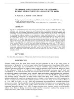
conditions. Fig. 1 presents a scheme of the different configurations of
these two catalytic filters.
Catalytic filters with a catalyst fixed bed (FB) are shown in Fig. 1A.
They present a high catalytic potential given their flexibility to integrate
a custom-made tar reforming catalyst and their capability to integrate
high amount of this catalyst in the hollow cylindrical space inside the filter candle considering the limitations imposed by the total weight of the
candle and the price of the catalyst incorporated. However, face velocities referred to the outer surface of the catalytic filter candle should be
limited to allow enough residence time for the catalytic tar reforming
reaction [15].
Studies about the optimum composition of the fixed bed catalyst can
be found in literature. Nacken et al. [13] tested several tar reforming catalyst systems of different NiO loadings. They evaluated the effect of the
variation of the catalyst support material, the preparation conditions,
the NiO loading and the effect of doping with ruthenium on the catalytic
activity of the tar reforming catalyst. The catalytic activity tests were
conducted using naphthalene as model tar compound. The highest catalytic reforming activity was found for a MgO supported Ni catalyst with
a NiO loading of 6 wt%. With this catalyst, complete naphthalene conversion at 800 °C during 100 h operation even in the presence of H2S
was reached. Therefore, this catalytic filter was tested in a larger scale.
A catalytic filter candle of adequate dimensions was manufactured
and inserted in the freeboard of a bubbling fluidized bed gasifier
where crushed almond shells were used as feedstock [17]. Gas and hydrogen yields were notably increased with the use of this catalytic filter
and tar content at the outlet of the catalytic filter was between 0.7 and
0.95 g/Nm3 (N2 free, d.b.). Besides, stable performance of the filter was
observed after 22 h of gasification.
The catalytic filters with catalytic coating on the porous support of
the conventional hot gas ceramic filter are denoted as catalytic layer filters (CL) (Fig. 1B). This design of catalytic filter had already been tested
for combined particle separation and NOx removal from laboratory [18]
to pilot scale [19]. The advantages of the catalytic layer filters is that
higher face velocities can be used compared to the fixed bed catalytic filters and therefore the size and weight of the catalytic filter could be reduced. This also implies that for the same outer diameter and superficial
velocity higher residence time can be achieved when compared to the
fixed bed catalytic filters. Besides a simplification of the manufacture
process compared to the fixed bed filters is also expected [15]. The possibility of integration of a tar reforming catalyst as a catalytic layer by
catalytic activation of 10 mm thick alumina based filter disks was first
117
demonstrated [10,20,21]. Then, several studies were carried out aiming
at finding suitable catalytic systems for the pore walls of ceramic filters
which combine high surface support materials and active catalysts [11,
15]. In these studies, MgO and CaO-Al2O3 were used as supports as well
as MgO-CaO and MgO-Al2O3. In some cases, they were doped with
La2O3, olivine or ZrO2. In all cases, the coated filters were catalytically activated by impregnation with the appropriate aqueous solution of nickel
nitrate hexahydrate to adjust the NiO loading amounts of 6 and 60 wt%
related to the amount of catalyst support [15]. The catalytic activity was
evaluated in all the cases using naphthalene as model tar compound.
Promising materials were selected to manufacture filter candles to be
tested in the freeboard of a bubbling fluidized bed [22]. In these experiments, tar conversion extent obtained by means of the catalytic filter
was around 58% with final tar contents in the gas around 0.8 g/Nm3
(N2 free, d.b.). Methane was also partially converted (28%). As a result,
a significant increase in the gas yield (15%) and in hydrogen concentration was reported.
Modifications and improvements of the first design of catalytic layer
filters (CL) have been recently presented. First, the replacement of SiC as
filter material with another material which could withstand the high
gasifier freeboard temperatures (between 800 and 850 °C) was accomplished. SiC was initially used due to the high heat conductivity and
good thermal shock resistance for cyclic back pulse cleaning of the catalytic filter [16]. However, it was replaced by Al2O3 which allowed long
operating times at 850 °C [23]. One of the new configurations for catalytic layer filter candles included an additionally integrated catalyst: a
catalytically activated Al2O3-based hollow-cylindrical monolith integrated in the hollow cylindrical space of the catalytic filter candle [24].
The incorporation of the monolith increased the Ni load of the catalytic
filter. Promising results were obtained with this new design of catalytic
layer filter candles (CL + M). Using the same experimental apparatus at
the same operating conditions [23], tar conversion of 93.5% was reached
with the use of the catalytically activated monolith in comparison with
the 58% tar conversion of the catalytic layer SiC candle. Results were also
better than those obtained for SiC candle of fixed bed design, where 79%
tar conversion was obtained. The final tar content of the clean gas was
around 0.25 g/Nm3 (N2 free, d.b.). A catalytically activated ceramic
foam as additional reforming step for integration into the hollow-cylindrical space of the catalytically activated filter candle was used
(CL + Foam). The catalytic activity of this combination at different superficial velocities was first examined using naphthalene as model tar
compound [25]. Based on these results, a catalytic filter of combined
Fig. 1. Scheme of configurations of catalytic filters: (A) fixed bed and (B) catalytic layer.
Adapted from Hackel et al. [16] and Nacken et al. [15].
118
L.F. de Diego et al. / Fuel Processing Technology 152 (2016) 116–123
design was developed allowing a reduction of the manufacturing costs
compared to those previously reported for catalytic filter candles of
fixed bed design, because the catalyst grain filling procedure to realize
the fixed bed was avoided [24]. The combined catalytic filter was tested
with naphthalene as model tar compound and also in experiments in a
bubbling fluidized bed gasifier [12] showing good performance. The hydrogen content was increased up to 56% (from 39% without catalytic filter) and the tar content was equal to 0.14 g/Nm3 (N2 free, d.b.).
In the present work, a comparison of the tar abatement performance
of catalytic filters with different designs is presented. Four catalytic filter
designs were tested: fixed bed (FB), fixed bed with catalytically active
inner tube (FB + CL), catalytic layer (CL) and catalytic layer with additional monolith (CL + M). The fact that not a biomass tar model compound but real biomass tar produced in situ in a dual fluidized bed
gasifier was used in all the catalytic activity tests adds novelty and applicability to the results presented.
2. Experimental
2.1. Dual fluidized bed gasification plant
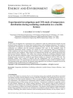
Biomass gasification was carried out in a bench-scale dual fluidized
bed gasification plant located at ICB-CSIC (Fig. 2) and described in a previous work from the authors [26]. The gasification plant consisted of
two interconnected fluidized beds. The gasifier was a bubbling fluidized
bed where biomass was fed in. The biomass used was pine wood with
an average particle size of 0.5–2.0 mm. The proximate and ultimate
analyses of biomass are shown in Table 1. Steam was used as gasifying
agent for biomass. The gasifier bed consisted of Fe/olivine in the size
range 0.1–0.25 mm. Fe/olivine material was prepared by impregnation.
Iron nitrate (Fe(NO3)3·9H2O) was dissolved in heated water and olivine
was added to the iron aqueous solution. The excess water was
Table 1
Proximate and ultimate analysis of pine wood (wt.%).
Moisture
Ash
Volatiles
Fixed carbon
C
H
N
S
Cl
High heating value (kJ/kg)
6.30
1.10
77.30
15.40
46.60
6.00
0.20
0.004
0.002
18,235
eliminated and the sample dried before being calcined for 4 h at
1000 °C. The final content of Fe in the Fe/olivine used was 16%. A more
detailed description of the preparation method of the Fe/olivine can
be found elsewhere [26]. After biomass gasification, the solids leaving
the gasifier were transferred to the combustor through another bubbling fluidized bed acting as a loop seal to avoid mixing gaseous atmospheres. The char which was not gasified was burned in the
combustor. Hot particles were then returned to the gasifier through a
riser.
The tar produced in situ during biomass gasification was used in the
catalytic activity tests of the different filter candles used in the present
work. The catalytic filters were located downstream the gasifier prior
to the tar measurement as it is shown in Fig. 2. The filter was placed inside a reactor and heated by a furnace to control the temperature inside
the filter. Once the tar has been collected for measurement, several gas
analysers were used to determine the composition of the gas product
streams: CO, CO2 and CH4 concentration was measured in a non-dispersive infrared (NDIR) analyser and H2 using a thermal conductivity detector. Moreover, the presence of C2-C3 hydrocarbons was also
analysed off-line using a gas chromatograph (HP 5890) with a Poropack
Fig. 2. Scheme of the dual fluidized bed gasifier.
L.F. de Diego et al. / Fuel Processing Technology 152 (2016) 116–123
N column. It was possible to by-pass the catalytic filter in order to determine the composition of the gaseous stream at the inlet of the catalytic
filter.
2.2. Tar sampling and analysis
Tar sampling and analysis was based on the European Tar Protocol
[27]. Moisture and tar were collected in impingers filled with
isopropanol. Water content of the tar was determined using the Karl-Fischer titration method (CRISON Titromatic KF1S). A gas chromatograph
(Agilent 7890A) coupled with a mass spectrometer (Agilent 5975C) was
used in the determination of the concentration of the different tar compounds in the samples collected from the impingers. The GC was fitted
with a capillary column (HP-5) and a flame ionization detector.
2.3. Catalytic filters
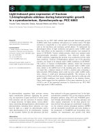
Four different catalytic filter designs were tested in the biomass gasification unit previously described. Their scheme is shown in Fig. 3. All of
them were supplied by Pall Filtersystems GmbH with the following
specifications:
-
DeTarCat FB (Fixed Bed)
DeTarCat FB + CL (catalytically active inner tube)
DeTarCat CL (Catalytically active Layer)
DeTarCat CL + M (catalytically active monolith inside).
In all cases, a 21 mm-height filter segment taken from the corresponding full-size filter candle was used for testing. Results can be considered as representative on small-scale of the behaviour of the full size
filter candle. The segment was covered with ceramic caps at the bottom
and upper part of the filter.
In the catalytic filter fixed bed design (DeTarCat FB), MgO powder
with a BET surface of about 0.15 m2/g and catalytically impregnated
with NiO was filled as fixed catalyst bed into the cylindrical space between two porous silicon carbide tubes. The silicon carbide tube has
an open pore volume of 38 vol%. In a second embodiment of the fixed
119
bed design, the inner porous tube was made of silicon carbide and additionally catalytically activated by a MgO-NiO coating (DeTarCat
FB + CL). For the DeTarCat CL design, a porous alumina based filter
tube with an open pore volume of 45 vol% was catalytically impregnated with MgO-Al2O3 supported NiO. In the fourth design tested, the catalyst amount of the catalytic layer design was further increased by
integration of an alumina foam tube into the interior of the alumina filter element tube (DeTarCat CL + M). The alumina foam tube with an
open pore volume of 71 vol% was also catalytically impregnated with
MgO-Al2O3 supported NiO. Table 2 presents a summary of the main
characteristics of the four catalytic filter designs tested.
2.4. Experimental plan
Table 3 summarizes the tests performed with the different catalytic
filters tested. Once the steady state was reached, tars produced in the
gasifier were measured bypassing the catalytic filter. This measurement
was considered as a reference test and corresponds to the tar composition at the catalytic filter inlet. After the reference was set, the gasification gas was forced to pass through the catalytic filter. Tar
measurements at the outlet of the catalytic filter were then performed
and the clean gas was sent to the analysers. To determine the tar conversion efficiency of the catalytic filter, the tar reference data were compared to the tar measurements after passing through the catalytic
filter. It was intended that the amount and composition of tar at the
inlet of the catalytic filter were similar for all the experiments performed. Two gasification parameters were maintained roughly constant
in order to reach this condition. First, the temperature in the biomass
gasifier was set to 800 °C in all the cases. The second parameter was
the H2O/biomass ratio. In our experiments, it varied between 0.52 and
0.68, which produced a variation in the characteristics of the tar produced in the gasifier and it was considered in the treatment of the
results.
Regarding the catalytic filter operating conditions, the influence of
two parameters was evaluated. On one hand, two temperatures of the
catalytic filter were tested, 800 and 850 °C, according to the recommendations made by the supplier. On the other hand, the face velocity was
varied in order to determine its influence on the performance of the
Fig. 3. Gas path through the catalytic filter segments for the four different catalytic filter designs: (A) fixed bed (FB), (B) fixed bed with catalytically active inner tube (FB + CL), (C) catalytic
layer (CL) and (D) catalytic layer with additional monolith (CL + M). Ceramic filter ; catalytic fixed bed ; catalytic layer ; catalytic foam ; ceramic caps . (For interpretation of the
references to color in this figure legend, the reader is referred to the web version of this article.)
120
L.F. de Diego et al. / Fuel Processing Technology 152 (2016) 116–123
Table 2
Characteristics of the catalytic filters used.
DeTarCat
Fixed bed design
Catalytic filter configuration
Sample notation
Filter support
Maximum temperature in operation (°C)
Filter candle dimensions (A × B × C × D)a (mm)
Composition
Catalyst support density (g/cm3)
FB
SiC
800
70 × 50 × 30 × 16
MgO supported Ni
1.7552 (FB)
NiO density (g/cm3)
0.1053 (FB)
Differential pressure (mbar)
(25 °C; face velocity = 90 m/h)
18.5
DeTarCat
Catalytic layer design
FB + CL
SiC
800
70 × 50 × 30 × 16
CL
Al2O3
900
60 × 40
1.7086 (FB)
0.0110 (CL)
0.1026 (FB)
0.0124 (CL)
51.6
0.0210 (CL)
CL + M
Al2O3
900
60 × 40 × 34 × 15
MgO-Al2O3 Ni
0.0147 (CL)
11.1
0.0175 (CL)
0.0483 (M)
0.0144 (CL)
0.0222 (M)
13.4
a
FB design: A: catalytic filter outer diameter. B: FB outer diameter. C: FB inner diameter. D: inner tube inner diameter. CL design: A: CL outer diameter. B: CL inner diameter. C: monolith
outer diameter. D: monolith inner diameter.
filter for tar abatement. The face velocity was defined as the ratio between the gas flow and the filter external area. Finally, the cumulative
time of each type of filter was also presented in Table 3. The total operation time for each type of catalytic filter is bold marked.
3. Results and discussion
3.1. Comparison of tar conversion
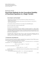
Fig. 4 presents the comparison of the amount of tar and the corresponding tar conversion obtained at the catalytic filter outlet when
the four different catalytic filters were used. The values are represented
versus the corresponding values of face velocities used. In Fig. 4, closed
symbols are used to represent tar reference values and open symbols for
the tar content at the catalytic filter outlet. The amount of tar in the gas
at catalytic filter inlet oscillates between 2.5 and 4.5 g/Nm3 for all the experiments performed.
In the experiments with the catalytic filter with a fixed bed design
(FB), the temperature in the filter was set to 800 °C. This was the maximum operating temperature allowed by the manufacturer considering
that SiC is the filter support material. The effect of the face velocity on
the tar content and conversion is clearly seen. The highest the face velocity, the larger the tar content at the catalytic filter outlet and therefore, the lower the tar conversion reached. This fact can be attributed
to a decrease in the residence time of the gasification gas inside the filter
when the face velocity increases as it has been observed before by the
authors for this type of catalytic filters [28]. The tar conversion decreased from 85 to around 50% when the face velocity increased from
40 to 87 m/h. At the lowest face velocity tested (40 m/h) the tar content
was 0.7 g/Nm3.
If an internal catalytically active inner tube is added to the catalytic
filter with a fixed bed design (FB + CL), the resulting filter configuration
improves tar removal. Experiments were performed at the same temperature in the filter as the experiments with the catalytic filter with
fixed bed design (FB), i.e. 800 °C. In this case, the effect of face velocity
on the tar content at the catalytic filter outlet is softened. The tar content
in the experiment at the lowest face velocity (46 m/h) was 0.8 g/Nm3.
Tar conversion values decreased with the increase in the face velocity,
although the decrease was not as sharp as in the previous experiments
with the FB catalytic filter. Tar conversion values were around 75%.
The use of catalytic filters with catalytically active layer (CL) allowed
an improvement in tar conversion when compared to FB and FB + CL
catalytic filters at 800 °C. Moreover, it is possible to operate at higher
temperatures than with the other two catalytic filters as Al2O3 is used
as filter support material in the CL catalytic filters. At 850 °C, the tar content at the outlet of the CL catalytic filter was decreased to 0.3 g/Nm3.
This corresponds to a tar removal efficiency of 88%, higher than that
found with FB-based catalytic filters. It must be also mentioned that
the difficulty in the tar removal process increases as tar content
decreases.
The results obtained with the CL catalytic filter were further improved when a monolith was integrated in the hollow cylindrical
space of the catalytic filter (CL + M). Actually, the best results in this
work were obtained using this catalytic filter configuration. Again, temperatures up to 850 °C could be reached with this type of filter, which
also contributed to its better performance in tar removal. For face velocities around 70 m/h, the tar removal efficiency at 800 °C was 80% and it
increased up to 95% at 850 °C. The later efficiency value corresponds to a
tar content at the outlet of the catalytic filter 0.2 g/Nm3, which can be
considered as excellent taking into account the very high tar content
at the inlet of the catalytic filter (about 4.5 g/Nm3). These results
Table 3
Experimental tests with the four DeTarCat catalytic filter elements.
Test
Type of DeTarCat catalytic filter
Tgasifier
(°C)
H2O/biomass dry
(g/g)
Tfilter
(°C)
Face velocity
(m/h)
Cumulative time
(h)
1
2
3
4
5
6
7
8
9
10
11
12
FB
FB
FB
FB
FB + CL
FB + CL
FB + CL
CL
CL
CL + M
CL + M
CL + M
800
800
800
800
800
800
800
800
800
800
800
800
0.59
0.52
0.52
0.59
0.66
0.66
0.66
0.64
0.59
0.68
0.66
0.66
800
800
800
800
800
800
800
800
850
800
850
850
40
67
75
87
46
70
80
83
72
69
96
67
1.0
2.2
3.2
4.0
1.7
2.9
3.9
1.2
2.5
1.2
2.7
4.0
L.F. de Diego et al. / Fuel Processing Technology 152 (2016) 116–123
121
Fig. 4. (A) Tar amount and (B) tar conversion as a function of the face velocity for the different designs of catalytic filters tested at 800 or 850 °C (Tg = 800 °C). Closed symbols = reference
values; open symbols = values at the catalytic filter outlet.
confirm previous findings by Rapagnà et al. [23] which also pointed to
the CL + M design for catalytic filters as the most promising for efficient
biomass tar removal above the FB or CL catalytic filter designs.
In the comparison between fixed bed (FB) and catalytically active
layer (CL) catalytic filters it should be born in mind that due to their design characteristics higher residence time can be expected for a CL catalytic filter than for the same fixed bed filter with the same candle outer
diameter and at the same superficial velocity. Considering this, the
values of the gas hourly space velocity (GHSV) were calculated for the
experiments performed with the different types of catalytic filters tested with the aim of facilitating the comparison. Table 4 summarizes the
values obtained. In the case of FB catalytic filters, larger GHSV values
were observed compared to the other three catalytic filters. Therefore,
shorter residence times for the gasification gas in the catalytic filter
can be expected. Nevertheless, these values were close to those reported by Nacken et al. [11] for similar FB catalytic filters in experiments to
evaluate the catalytic activity using naphthalene as model tar compound. They performed 50 h long–term tests at 800 °C and observed
100% naphthalene conversion at GHSV of 3120 h−1 and 99.3% conversion at GHSV of 4160 h−1.
Another aspect to take into account is the pressure drop in the catalytic filter. Measurements were performed during operation with the
four types of catalytic filters. Results are shown in Fig. 5. As expected,
higher face velocities lead to a higher pressure drop through the catalytic filter in all types of filters. Nevertheless, the pressure drop registered
for the FB + CL catalytic filter is notably higher than for the rest of the
filters tested. It oscillated between 30 and 43 mbar while for the rest
the values varied between 9 and 23 mbar in the tests. This fact represents an additional disadvantage for the further use of this type of catalytic filter. In comparison to that, the pressure drop measured for the
CL + M catalytic filter is not especially higher when compared to that
of FB and CL catalytic filters, because the catalytically activated monolith
creates no additional differential pressure under the applied superficial
flow conditions. This result together with the high tar conversion obtained in the experiments with this catalytic filter makes this
configuration the most promising for further development among all
those studied in the present work.
3.2. Comparison of syngas and tar composition
The composition of syngas and tar at the inlet and outlet of the catalytic filters was measured. Selected operating conditions of 800 °C in
the catalytic filter and face velocities around 70–80 m/h were chosen
in all the cases in order to compare the results for the different filters.
Table 5 presents the operating conditions and experimental results for
the different catalytic filters including the syngas composition in dry
and N2 free basis. From these values, the H2 production and conversion
of the other gases was calculated as the ratio between the variation of
moles through the catalytic filter (outlet minus inlet) and the moles at
the inlet. In all the cases, an increase in H2 at the outlet of the catalytic
filter was observed, as it was reported before by other authors [12,22].
The largest increment was observed for the FB filter, probably due to a
high catalyst amount present in the fixed bed. Among the CL catalytic
configuration, the largest H2 production was observed for the CL + M
filter. This result agrees with the observed by other authors when
using this type of catalytic filter [23].
Tar composition is also plotted in Fig. 6 for more clarity. In all the
cases, the major tar compounds at the inlet of the catalytic filter were
naphthalene, indene and biphenylen. At the catalytic filter outlet, naphthalene was the major compound and in some cases almost the only tar
compound that could be detected in significant level. However, it suffered a significant drop during its passage through the catalytic filter.
Table 4
Gas hourly space velocity (GHSV).
Type of DeTarCat catalytic filter
Tfilter
(°C)
GHSV
(h−1)
FB
FB + CL
CL
CL + M
800
800
800–850
800–850
1800–3900
1470–2550
2090–2545
1550–1915
Fig. 5. Differential pressure in the catalytic filter as a function of the face velocity for the
different designs of catalytic filters tested at 800 or 850 °C (Tgasif. = 800 °C).
122
L.F. de Diego et al. / Fuel Processing Technology 152 (2016) 116–123
Table 5
Operating conditions and experimental results for the different catalytic filters.
Catalytic filter
Filter temperature (°C)
Filter gas velocity (m/h)
Filter pressure drop (mbar)
Operating conditions
Biomass (g/h)
H2O/biomass dry (g/g)
Gas composition (vol%)
Gasifier (N2 free. dry basis)
CO
CO2
H2
CH4
C2H4
C2H6
C3H8
Combustor
O2
CO2
Tar (g/Nm3 dry)
H2O content (vol%)
Tar conversion (%)
Tar composition (g/Nm3 dry)
Styrene
Phenol
Benzofuran
Indene
Naphthalene
Biphenylen
Fluorene
Phenanthrene
Anthracene
Fluoranthene
Pyrene
a
DeTarCat
FB
DeTarCat
FB + CL
Inlet
Outlet
800
800
67
16
Xa (%)
Inlet
Outlet
800
800
70
39
258
0.52
21.7
37.8
27.2
9.2
3.3
0.4
0.3
19.1
32.4
37.6
7.5
2.7
0.3
0.2
15.6
2.7
3.89
42.9
0.21
0.00
0.23
0.96
1.94
0.24
0.04
0.15
0.02
0.05
0.05
DeTarCat
CL
Xa (%)
Inlet
Outlet
800
800
83
20
244
0.66
3.3
0.6
62.3
−4.3
−3.9
−11.9
−21.7
15.7
47.0
24.9
8.6
3.1
0.4
0.3
13.7
44.0
32.4
7.0
2.4
0.3
0.2
15.6
2.6
1.12
34.1
71
15.6
1.9
3.04
43.6
0.00
0.00
0.00
0.00
1.11
0.00
0.00
0.00
0.00
0.01
0.00
0.14
0.23
0.07
0.46
1.52
0.33
0.05
0.12
0.03
0.03
0.02
DeTarCat
CL + M
Xa (%)
Inlet
Outlet
800
800
77
22
246
0.64
−2.3
4.8
45.7
−8.8
−13.3
−16.0
−25.3
16.9
43.6
27.3
8.5
3.1
0.4
0.2
14.2
42.6
32.9
7.2
2.6
0.3
0.2
15.3
1.8
0.84
37.9
72
16.0
1.9
3.41
44.3
0.02
0.00
0.00
0.03
0.73
0.03
0.00
0.03
0.00
0.00
0.00
0.17
0.28
0.08
0.53
1.64
0.35
0.06
0.15
0.03
0.04
0.03
Xa (%)
244
0.68
−8.8
6.0
31.4
−7.2
−6.2
−7.8
−20.9
18.4
40.5
27.9
9.2
3.3
0.4
0.3
16.6
36.6
35.8
7.7
2.8
0.3
0.2
15.9
1.8
0.93
39.6
73
16.3
1.7
3.42
45.5
15.9
1.8
0.69
34.3
80
0.02
0.00
0.00
0.02
0.81
0.04
0.00
0.03
0.00
0.00
0.01
0.17
0.24
0.08
0.57
1.54
0.32
0.13
0.16
0.04
0.09
0.04
0.00
0.00
0.00
0.01
0.65
0.01
0.00
0.02
0.00
0.00
0.00
1.8
2.0
44.8
−5.5
−4.2
−15.3
−24.7
H2 production or gas conversion.
Naphthalene conversion was 42.8% for the FB catalytic filter and 52.0%
for the FB + CL filter. In the case of the catalytic layer filters, naphthalene conversion reached 50.6% for the CL filter and 57.8% for the
CL + M filter.
Fig. 6. Tar composition at the inlet and outlet of the catalytic filter for the different catalytic
filters tested with Tfilter = 800 °C and face velocity = 70–80 m/h. (Tgasif. = 800 °C).
Considering all the results presented above, some guidelines for future optimization of the use of catalytic filters in tar abatement during
biomass gasification could be indicated. Obviously, primary measures
for tar reduction should be applied in the gasifier in order to decrease
the tar concentration at the gasifier outlet (i.e. the catalytic filter inlet)
as much as possible. Temperature and gas flow to be treated are the
most important variables affecting the design of a catalytic filter. Although high temperatures favor tar conversion, some materials used
in catalytic filters manufacture can limit its use at temperatures below
800 °C, i.e. SiC.
In addition, the syngas flow to be cleaned would determine the
number of catalytic filters to be used. Low face velocities, large filter diameters and wall thickness with increasing catalyst load lead to an increase in the residence time for tar and hydrocarbons in the catalytic
filter, favoring tar abatement. However, these parameters should be optimized so that a compromise is reached between the tar abatement efficiency and the weight and pressure drop through the filter,
considering that the catalytic filter would hang in the freeboard of the
gasifier. In this sense, the values of the parameters used in this work
can be considered as normal in a future application of these catalytic filters in an industrial gasifier.
Regarding the results obtained in our experiments, the lowest values
obtained were 0.2 g/Nm3. This value is still far from the limits set for applications with high quality gas requirements (b1 mg/Nm3) such as
methanol production or the combustion in a fuel cell. However, it
would be easier to reach the specifications for combustion in gas engines or turbines. Although different values are given in literature, the
maximum allowable concentration would be 100 mg/Nm3 [9]. Modeling calculations based on experimental results for the fixed bed catalytic
filters presented in this work showed that tar contents below 0.1 g/Nm3
L.F. de Diego et al. / Fuel Processing Technology 152 (2016) 116–123
can be reached with catalytic filter thickness of 25 mm. However, pressure drop and weight should be reduced in this configuration. Catalytic
layer filter design could reach similar tar abatement efficiency with less
restriction regarding pressure drop and weight.
4. Conclusions
Four different design configurations of catalytic filter for hot gas conditioning have been tested in biomass gasification experiments. These
are based on different possibilities to include the catalyst: in a fixed
bed or inside a catalytically active layer. This novel tar abatement technology has been evaluated using real biomass tar produced in situ in a
dual fluidized bed gasifier (DFBG). The effect of temperature and face
velocity was evaluated in order to optimize tar abatement.
The most promising catalytic filter design is the catalytic layer integrated with a catalytically activated alumina foam tube (CL + M design). High tar removal efficiencies up to 95% at 850 °C with
corresponding tar contents down to 0.2 g/Nm3 have been achieved.
This design provides a technically feasible solution for combined tar
and particulate removal with high performance at acceptable differential pressure under operating conditions.
Further optimization of the catalytic filter design would be needed in
order to use the syngas in gas engines or turbines. However, for applications with more restricted requirements, such as methanol production
or the use in a fuel cell, additional cleaning downstream the gasifier
would be needed.
Acknowledgments
This work was supported by the European Commission (EC Project
UNIQUE No. 211517-ENERGY FP7-2008/2011) and the Spanish Ministry
MINECO (ENE2014-56857-R). T. Mendiara thanks for the “Ramón y
Cajal” post-doctoral contract awarded by the Spanish Ministry of Economy and Competitiveness. Cristina Igado is also acknowledged for her
contribution to the experimental work.
References
[1] G. Xu, T. Murakami, T. Suda, Y. Matsuzawa, H. Tani, The superior technical choice for
dual fluidized bed gasification, Ind. Eng. Chem. Res. 45 (2006) 2281–2286.
[2] M. Bolhàr-Nordenkampf, R. Rauch, K. Bosch, C. Aichernig, H. Hofbauer, Biomass CHP
Plant Güssing-Using Gasification for Power Generation, International Conference on
Biomass Utilisation, 2002.
[3] M.C. Seemann, H. Thunman, The New Chalmers Research-gasifier, International
Conference on Polygeneration Strategies, 2009.
[4] R. Ghidossi, J.P. Bonnet, G. Rebollar-Perez, E. Carretier, J.H. Ferrasse, J. Vicente, F.
Topin, P. Moulin, Separation of particles from hot gases using metallic foams, J.
Mater. Process. Technol. 209 (2009) 3859–3868.
[5] P.J. Kilgallon, N.J. Simms, J.F. Norton, J.E. Oakey, Metallic components in coal-gasification fuel gas paths, J. Corros. Sci. Eng. 6 (2003).
[6] S.D. Sharma, M. Dolan, D. Park, L. Morpeth, A. Ilyushechkin, K. McLennan, D.J. Harris,
K.V. Thambimuthu, A critical review of syngas cleaning technologies - fundamental
limitations and practical problems, Powder Technol. 180 (2008) 115–121.
123
[7] K. Maniatis, A.A.C.M. Beenackers, Tar protocols. IEA bioenergy gasification task: introduction, Biomass Bioenergy 18 (2000) 1–4.
[8] A.V. Bridgwater, The technical and economic feasibility of biomass gasification for
power generation, Fuel 74 (1995) (631–53).
[9] H.A.M. Knoef, Handbook Biomass Gasification, BTG Biomass Technology Group, Enschede, The Netherlands, 2005.
[10] K. Engelen, Y. Zhang, D.J. Draelants, G.V. Baron, A novel catalytic filter for tar removal
from biomass gasification gas: improvement of the catalytic activity in presence of
H2S, Chem. Eng. Sci. 58 (2003) 665–670.
[11] M. Nacken, L. Ma, S. Heidenreich, G.V. Baron, Catalytic activity in naphthalene
reforming of two types of catalytic filters for hot gas cleaning of biomass-derived
syngas, Ind. Eng. Chem. Res. 49 (2010) 5536–5542.
[12] A. D'Orazio, S. Rapagnà, P.U. Foscolo, K. Gallucci, M. Nacken, S. Heidenreich, A. Di
Carlo, A. Dell'Era, Gas conditioning in H2 rich syngas production by biomass steam
gasification: experimental comparison between three innovative ceramic filter candles, Int. J. Hydrog. Energy 40 (2015) 7282–7290.
[13] M. Nacken, M. Lina, K. Engelen, S. Heidenreich, G.V. Baron, Development of a tar
reforming catalyst for integration in a ceramic filter element and use in hot gas
cleaning, Ind. Eng. Chem. Res. 46 (2007) 1945–1951.
[14] M.M. Yung, W.S. Jablonski, K.A. Magrini-Bair, Review of catalytic conditioning of biomass-derived syngas, Energy Fuel 23 (2009) 1874–1887.
[15] M. Nacken, L. Ma, S. Heidenreich, G.V. Baron, Performance of a catalytically activated
ceramic hot gas filter for catalytic tar removal from biomass gasification gas, Appl.
Catal. B Environ. 88 (2009) 292–298.
[16] M. Hackel, G. Schaub, M. Nacken, S. Heidenreich, Kinetics of reduction and oxidation
reactions for application in catalytic gas-particle-filters, Powder Technol. 180 (2008)
239–244.
[17] S. Rapagnà, K. Gallucci, M. di Marcello, M. Matt, M. Nacken, S. Heidenreich, P.U.
Foscolo, Gas cleaning, gas conditioning and tar abatement by means of a catalytic filter candle in a biomass fluidized-bed gasifier, Bioresour. Technol. 101 (2010)
7123–7130.
[18] M. Nacken, S. Heidenreich, M. Hackel, G. Schaub, Catalytic activation of ceramic filter
elements for combined particle separation, NOx removal and VOC total oxidation,
Appl. Catal. B Environ. 70 (2007) 370–376.
[19] S. Heidenreich, M. Nacken, M. Hackel, G. Schaub, Catalytic filter elements for combined particle separation and nitrogen oxides removal from gas streams, Powder
Technol. 180 (2008) 86–90.
[20] L. Ma, H. Verelst, G.V. Baron, Integrated high temperature gas cleaning: tar removal
in biomass gasification with a catalytic filter, Catal. Today 105 (2005) 729–734.
[21] L. Ma, G.V. Baron, Mixed zirconia-alumina supports for Ni/MgO based catalytic filters for biomass fuel gas cleaning, Powder Technol. 180 (2008) 21–29.
[22] S. Rapagnà, K. Gallucci, M.D. Marcello, P.U. Foscolo, M. Nacken, S. Heidenreich, In situ
catalytic ceramic candle filtration for tar reforming and particulate abatement in a
fluidized-bed biomass gasifier, Energy Fuel 23 (2009) 3804–3809.
[23] S. Rapagnà, K. Gallucci, M. Di Marcello, P.U. Foscolo, M. Nacken, S. Heidenreich, M.
Matt, First Al2O3 based catalytic filter candles operating in the fluidized bed gasifier
freeboard, Fuel 97 (2012) 718–724.
[24] M. Nacken, G.V. Baron, S. Heidenreich, S. Rapagnà, A. D'Orazio, K. Gallucci, J.F.M.
Denayer, P.U. Foscolo, New DeTar catalytic filter with integrated catalytic ceramic
foam: catalytic activity under model and real bio syngas conditions, Fuel Process.
Technol. 134 (2015) 98–106.
[25] M. Nacken, L. Ma, S. Heidenreich, F. Verpoort, G.V. Baron, Development of a catalytic
ceramic foam for efficient tar reforming of a catalytic filter for hot gas cleaning of
biomass-derived syngas, Appl. Catal. B Environ. 125 (2012) 111–119.
[26] M. Virginie, J. Adánez, C. Courson, L.F. De Diego, F. García-Labiano, D. Niznansky, A.
Kiennemann, P. Gayán, A. Abad, Effect of Fe-olivine on the tar content during biomass gasification in a dual fluidized bed, Appl. Catal. B Environ. 121–122 (2012)
214–222.
[27] P. Simell, P. Ståhlberg, E. Kurkela, J. Albrecht, S. Deutsch, K. Sjöström, Provisional
protocol for the sampling and analysis of tar and particulates in the gas from
large-scale biomass gasifiers. Version 1998, Biomass Bioenergy 18 (2000) 19–38.
[28] F. García-Labiano, P. Gayán, L.F. De Diego, A. Abad, T. Mendiara, J. Adánez, M. Nacken,
S. Heidenreich, Tar abatement in a fixed bed catalytic filter candle during biomass
gasification in a dual fluidized bed, Appl. Catal. B Environ. 188 (2016) 198–206.