Introduction – Equations of motion G. Dimitriadis 06
Bạn đang xem bản rút gọn của tài liệu. Xem và tải ngay bản đầy đủ của tài liệu tại đây (2.06 MB, 64 trang )
Aeroelasticity
Lecture 6:
Flight Flutter Testing
G. Dimitriadis
Introduction to Aeroelasticity
Flight flutter testing
•! Despite all the efforts in developing design
flutter tools, the only definitive method for
clearing aircraft for flutter is flight testing
•! All airworthiness and aircraft certification
procedures require that aerospace
constructors demonstrate that the flight
envelope of a new aircraft is clear of flutter.
•! In fact, for added security, there must be no
flutter at 20% outside the flight envelope
(15% for military aircraft)
Introduction to Aeroelasticity
Flight flutter history
•! The first flight flutter tests were very basic:
–! Aircraft would be flown to all the extremes of their
flight envelope.
–! If they survived then the aircraft was deemed safe
–! If they were destroyed then they had to be
redesigned
•! Clearly, this was not a satisfactory way of
carrying out such tests.
•! Von Schlippe performed the first formal flutter
tests in 1935 in Germany
Introduction to Aeroelasticity
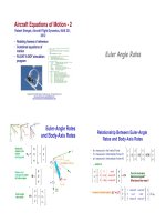
Von Schlippe’s test
•! Von Schlippe flew the aircraft
at an initially low airspeed.
•! He vibrated the aircraft
structures at its natural
frequencies at each airspeed
and plotted the resulting
vibration amplitude
•! He predicted flutter when the
amplitude reaches a high
value (theoretically infinite)
•! He estimated the natural
frequencies of the structure
during ground vibration tests
Introduction to Aeroelasticity
Further history
•! Von Schlippe’s technique continued to be
used until a Junkers Ju90 aircraft fluttered in
flight and crashed
•! The problems with the procedure were:
–! Inadequate structural excitation in flight
–! Inaccurate measurement of response amplitude
•! These problems could only be solved with
better instrumentation and excitation
capabilities - the method itself was sound
Introduction to Aeroelasticity
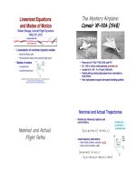
1940s
•! The Americans
used the same
technique in the
1940s
•! Example:
Cessna AT-8
aircraft
Introduction to Aeroelasticity
Progress
•! Von Schlippe’s flight flutter testing method
was good but the instrumentation not very
advanced.
•! Between the 50s and 70s several advances
in actuation and instrumentation brought
about significant improvements in flight flutter
testing
•! The response amplitude was replaced by the
damping ratio as the flutter parameter
Introduction to Aeroelasticity
F111 Flight test apparatus
Excitation using
aerodynamic wing
tabs
Introduction to Aeroelasticity
Typical modern apparatus
Introduction to Aeroelasticity
Excitation systems
•! An ideal excitation system must:
–! Provide adequate excitation levels at all the
frequency ranges of interest
–! Be light so as not to affect the modal
characteristics of the structure
–! Have electrical or hydraulic power
requirements that the aircraft can meet
Introduction to Aeroelasticity
Control surface pulses
•! This method consists of impulsively moving one of
the control surfaces and then bringing it back to zero
•! Theoretically, it is supposed to be a perfect impulse.
Such an impulse will excite all the structure’s modes
•! In practice it is not at all perfect and can only excite
modes of up to 10Hz
•! The transient response of the aircraft is easy to
analyse for stability
•! However, high damping rates and lots of
measurement noise can make this analysis difficult
•! The repeatability of pulses is low
Introduction to Aeroelasticity
Oscillating control surfaces
•! Instead of just pulsing the control surfaces,
we oscillate them sinusoidally
•! Three modes:
–! Dwell: Oscillation at constant frequency and
amplitude
–! Frequency sweep: oscillation at constant
amplitude but linearly increasing frequency
–! Amplitude sweep: oscillation at constant frequency
but linearly increasing amplitude
•! The demand signal is provided by the
automatic control system. The excitation is
accurate and can range from 0.1Hz to 100Hz.
Introduction to Aeroelasticity
Control surface excitation
FCC
Actuator
‘FBI’ Command
Digital Signal
Control
Surface
Introduction to Aeroelasticity
Thrusters
•! Aka bonkers, ballistic exciters, impulse
generators
•! These are small one-shot rockets that burn
for 20ms and provide thrust up to 2,000Kg.
•! They are attached at points that allow the
measurement of particular modes of interest
•! They are not used very much now. They have
several disadvantages:
–! Single shot
–! Difficult to fire two or more simultaneously
–! Need thrusters of different burn times to excite
different frequencies
Introduction to Aeroelasticity
Inertial exciters
Rotating eccentric weight or
oscillating weight inertial
exciters.
Many designs have been
used.
They are not very popular
nowadays
Their excitation capability is
low at low frequencies and
too high at high frequencies
Introduction to Aeroelasticity
Aerodynamic vanes
•! Small winglets usually mounted on tip of a wing or a
stabilizer
•! The vanes are mounted on a shaft and oscillate
around a mean angle
•! The force depends on the size of the vane, the
dynamic pressure and the oscillation angle
•! They excite low frequencies adequately
•! High frequency excitation depends on the frequency
response of the mechanism
•! Force depends on the square of the airspeed - at low
speeds it is low
Introduction to Aeroelasticity
Random atmospheric
turbulence
•! This method is completely free and does not
change the modal or control characteristics of
the aircraft at all.
•! On the other hand excitation levels can be
low (we cannot ensure adequate levels of
turbulence on test days)
•! The signal-to-noise ratio of the response data
is usually small
Introduction to Aeroelasticity
Von Karman Spectrum
•! The frequency content of atmospheric
turbulence is usually modelled using the Von
Karman spectrum
!11 (" ) = # g2
L
1
2 5/6
$% %
L' '
1
+
1.339
"
) &
V ( *(
&
Longitudinal turbulence
2
8%
L'
1 + 1.339"
L
3&
V(
Lateral turbulence
! 22 (" ) = # g2
2 11/ 6
$% %
L' '
1
+
1.339
"
) &
V ( *(
&
•! Where ! is the angular frequency, L=762m is
the length scale of atmospheric turbulence, V
is the aircraft’s airspeed, "g=2.1-6.4 is the
turbulence intensity
Introduction to Aeroelasticity
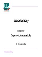
Von Karman example
Von Karman
spectrum at an
airspeed of
200m/s and
"g=2.1.
It can be seen
that most of the
power is
concentrated at
very low
frequencies, less
than 1Hz.
The power at
frequencies of
10Hz or more is
very low
Introduction to Aeroelasticity
Comparison of two excitation
systems
Response amplitude power spectra from exciter sweep and random turbulence
Introduction to Aeroelasticity
Summary of exciters
Introduction to Aeroelasticity
Excitation Signals
•! There are four main types of excitation
signals used:
–! Impulsive
–! Dwell
–! Sweep
–! Noise
•! Dwell only excites one frequency at a time.
Therefore, it is expensive since the test must
last longer.
•! Impulsive, sweep and noise excite many
frequencies at a time
Introduction to Aeroelasticity
Frequency sweep (chirp)
Frequency sweep from 1Hz to 30Hz
Time domain
Introduction to Aeroelasticity
Frequency domain
Noise
Uniform noise from 1Hz to 30Hz
Time domain
Introduction to Aeroelasticity
Frequency domain
Real test data example
Data obtained
during a flight
flutter test.
Three dwells
between 5Hz and
6Hz and one
sweep from 5Hz
to 7Hz.
Excitation is
control surface
deflection.
Introduction to Aeroelasticity