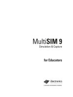
multisim 9 simulation and capture
Bạn đang xem bản rút gọn của tài liệu. Xem và tải ngay bản đầy đủ của tài liệu tại đây (2.4 MB, 108 trang )
Electronics
Workbench
TM
Multisim 9 Simulation and Capture
TM
Educators Manual
TitleShort-Hidden (cross reference text)
February 2006
371588B-01
Support
Worldwide Technical Support and Product Information
ni.com
National Instruments Corporate Headquarters
11500 North Mopac Expressway
Austin, Texas 78759-3504
USA Tel: 512 683 0100
Worldwide Offices
Australia 1800 300 800, Austria 43 0 662 45 79 90 0, Belgium 32 0 2 757 00 20, Brazil 55 11 3262 3599,
Canada 800 433 3488, China 86 21 6555 7838, Czech Republic 420 224 235 774, Denmark 45 45 76 26 00,
Finland 385 0 9 725 725 11, France 33 0 1 48 14 24 24, Germany 49 0 89 741 31 30, India 91 80 41190000,
Israel 972 0 3 6393737, Italy 39 02 413091, Japan 81 3 5472 2970, Korea 82 02 3451 3400,
Lebanon 961 0 1 33 28 28, Malaysia 1800 887710, Mexico 01 800 010 0793, Netherlands 31 0 348 433 466,
New Zealand 0800 553 322, Norway 47 0 66 90 76 60, Poland 48 22 3390150, Portugal 351 210 311 210,
Russia 7 095 783 68 51, Singapore 1800 226 5886, Slovenia 386 3 425 4200, South Africa 27 0 11 805 8197,
Spain 34 91 640 0085, Sweden 46 0 8 587 895 00, Switzerland 41 56 200 51 51, Taiwan 886 02 2377 2222,
Thailand 662 278 6777, United Kingdom 44 0 1635 523545
For further support information, refer to the Technical Support Resources and Professional Services page. To comment
on National Instruments documentation, refer to the National Instruments Web site at ni.com/info and enter the
info code feedback.
© 2005–2006 National Instruments Corporation. All rights reserved.
Important Information
Warranty
The media on which you receive National Instruments software are warranted not to fail to execute programming instructions, due to defects
in materials and workmanship, for a period of 90 days from date of shipment, as evidenced by receipts or other documentation. National
Instruments will, at its option, repair or replace software media that do not execute programming instructions if National Instruments receives
notice of such defects during the warranty period. National Instruments does not warrant that the operation of the software shall be
uninterrupted or error free.
A Return Material Authorization (RMA) number must be obtained from the factory and clearly marked on the outside of the package before
any equipment will be accepted for warranty work. National Instruments will pay the shipping costs of returning to the owner parts which are
covered by warranty.
National Instruments believes that the information in this document is accurate. The document has been carefully reviewed for technical
accuracy. In the event that technical or typographical errors exist, National Instruments reserves the right to make changes to subsequent
editions of this document without prior notice to holders of this edition. The reader should consult National Instruments if errors are suspected.
In no event shall National Instruments be liable for any damages arising out of or related to this document or the information contained in it.
EXCEPT AS SPECIFIED HEREIN, NATIONAL INSTRUMENTS MAKES NO WARRANTIES , EXPRESS OR IMPLIED, AND SPECIFICALLY DISCLAIMS ANY WARRANTY OF
MERCHANTABILITY OR FITNESS FOR A PARTICULAR PURPOSE . C USTOMER’S RIGHT TO RECOVER DAMAGES CAUSED BY FAULT OR NEGLIGENCE ON THE PART OF
NATIONAL INSTRUMENTS SHALL BE LIMITED TO THE AMOUNT THERETOFORE PAID BY THE CUSTOMER. NATIONAL INSTRUMENTS WILL NOT BE LIABLE FOR
DAMAGES RESULTING FROM LOSS OF DATA, PROFITS, USE OF PRODUCTS, OR INCIDENTAL OR CONSEQUENTIAL DAMAGES, EVEN IF ADVISED OF THE POSSIBILITY
THEREOF. This limitation of the liability of National Instruments will apply regardless of the form of action, whether in contract or tort, including
negligence. Any action against National Instruments must be brought within one year after the cause of action accrues. National Instruments
shall not be liable for any delay in performance due to causes beyond its reasonable control. The warranty provided herein does not cover
damages, defects, malfunctions, or service failures caused by owner’s failure to follow the National Instruments installation, operation, or
maintenance instructions; owner’s modification of the product; owner’s abuse, misuse, or negligent acts; and power failure or surges, fire,
flood, accident, actions of third parties, or other events outside reasonable control.
Copyright
Under the copyright laws, this publication may not be reproduced or transmitted in any form, electronic or mechanical, including photocopying,
recording, storing in an information retrieval system, or translating, in whole or in part, without the prior written consent of National
Instruments Corporation.
National Instruments respects the intellectual property of others, and we ask our users to do the same. NI software is protected by copyright and other
intellectual property laws. Where NI software may be used to reproduce software or other materials belonging to others, you may use NI software only
to reproduce materials that you may reproduce in accordance with the terms of any applicable license or other legal restriction.
Trademarks
National Instruments, NI, ni.com, and LabVIEW are trademarks of National Instruments Corporation. Refer to the Terms of Use section
on ni.com/legal for more information about National Instruments trademarks.
Other product and company names mentioned herein are trademarks or trade names of their respective companies.
Members of the National Instruments Alliance Partner Program are business entities independent from National Instruments and have no
agency, partnership, or joint-venture relationship with National Instruments.
Patents
For patents covering National Instruments products, refer to the appropriate location: Help»Patents in your software, the patents.txt file
on your CD, or ni.com/patents.
Some portions of this product are protected under United States Patent No. 6,560,572.
WARNING REGARDING USE OF NATIONAL INSTRUMENTS PRODUCTS
(1) NATIONAL INSTRUMENTS PRODUCTS ARE NOT DESIGNED WITH COMPONENTS AND TESTING FOR A LEVEL OF
RELIABILITY SUITABLE FOR USE IN OR IN CONNECTION WITH SURGICAL IMPLANTS OR AS CRITICAL COMPONENTS IN
ANY LIFE SUPPORT SYSTEMS WHOSE FAILURE TO PERFORM CAN REASONABLY BE EXPECTED TO CAUSE SIGNIFICANT
INJURY TO A HUMAN.
(2) IN ANY APPLICATION, INCLUDING THE ABOVE, RELIABILITY OF OPERATION OF THE SOFTWARE PRODUCTS CAN BE
IMPAIRED BY ADVERSE FACTORS, INCLUDING BUT NOT LIMITED TO FLUCTUATIONS IN ELECTRICAL POWER SUPPLY,
COMPUTER HARDWARE MALFUNCTIONS, COMPUTER OPERATING SYSTEM SOFTWARE FITNESS, FITNESS OF COMPILERS
AND DEVELOPMENT SOFTWARE USED TO DEVELOP AN APPLICATION, INSTALLATION ERRORS, SOFTWARE AND
HARDWARE COMPATIBILITY PROBLEMS, MALFUNCTIONS OR FAILURES OF ELECTRONIC MONITORING OR CONTROL
DEVICES, TRANSIENT FAILURES OF ELECTRONIC SYSTEMS (HARDWARE AND/OR SOFTWARE), UNANTICIPATED USES OR
MISUSES, OR ERRORS ON THE PART OF THE USER OR APPLICATIONS DESIGNER (ADVERSE FACTORS SUCH AS THESE ARE
HEREAFTER COLLECTIVELY TERMED “SYSTEM FAILURES”). ANY APPLICATION WHERE A SYSTEM FAILURE WOULD
CREATE A RISK OF HARM TO PROPERTY OR PERSONS (INCLUDING THE RISK OF BODILY INJURY AND DEATH) SHOULD
NOT BE RELIANT SOLELY UPON ONE FORM OF ELECTRONIC SYSTEM DUE TO THE RISK OF SYSTEM FAILURE. TO AVOID
DAMAGE, INJURY, OR DEATH, THE USER OR APPLICATION DESIGNER MUST TAKE REASONABLY PRUDENT STEPS TO
PROTECT AGAINST SYSTEM FAILURES, INCLUDING BUT NOT LIMITED TO BACK-UP OR SHUT DOWN MECHANISMS.
BECAUSE EACH END-USER SYSTEM IS CUSTOMIZED AND DIFFERS FROM NATIONAL INSTRUMENTS' TESTING
PLATFORMS AND BECAUSE A USER OR APPLICATION DESIGNER MAY USE NATIONAL INSTRUMENTS PRODUCTS IN
COMBINATION WITH OTHER PRODUCTS IN A MANNER NOT EVALUATED OR CONTEMPLATED BY NATIONAL
INSTRUMENTS, THE USER OR APPLICATION DESIGNER IS ULTIMATELY RESPONSIBLE FOR VERIFYING AND VALIDATING
THE SUITABILITY OF NATIONAL INSTRUMENTS PRODUCTS WHENEVER NATIONAL INSTRUMENTS PRODUCTS ARE
Preface
Congratulations on choosing Multisim 9 from Electronics Workbench. We are confident that
it will deliver years of increased productivity and superior designs.
Electronics Workbench is the world’s leading supplier of circuit design tools. Our products
are used by more customers than those of any other EDA vendor, so we are sure you will be
pleased with the value delivered by Multisim 9, and by any other Electronics Workbench
products you may select.
Installation
For complete installation instructions, refer to the installation chapter of the Multisim 9 User
Guide.
Documentation Conventions
When Multisim 9 guides refer to a toolbar button, an image of the button appears in the left
column.
Multisim 9 guides use:
•
•
•
the convention Menu/Item to indicate menu commands. For example, “File/Open” means
choose the Open command from the File menu.
an arrow ( ) to indicate the start of procedural information.
the construction CTRL-KEY and ALT-KEY to indicate when you need to hold down the
“Ctrl” or “Alt” key on your keyboard and press another key.
The Multisim 9 Documentation Set
All Multisim 9 Education edition users receive PDF versions of the Multisim 9 User Guide,
the Multisim 9 for Educators guide, the Component Reference Guide and online help.
User Guide
The User Guide describes Multisim 9 and its many functions in detail. It is organized based
on the stages of circuit design, and explains all aspects of using Multisim 9, in detail. It also
contains a tutorial that will introduce you to Multisim’s many features.
Multisim 9 for Educators
The Multisim 9 for Educators guide describes functions that are specific to the Education
edition of Multisim 9.
Online Help
Multisim offers a full helpfile system to support your use of the product.
Choose Help/Multisim Help to display the helpfile that explains the Multisim program in
detail, or choose Help/Component Reference to display the helpfile that contains details on the
components families provided with Multisim. Both are standard Windows helpfiles, offering
a table of contents and index.
In addition, you can display context-sensitive help by pressing F1 from any command or
window, or by clicking the Help button on any dialog box that offers it.
Adobe PDF Files
The Multisim 9 User Guide, Multisim 9 for Educators and the Component Reference Guide
are provided on the documentation CD as Adobe PDF files.
License Agreement
Please read the license agreement found at www.electronicsworkbench.com carefully before
installing and using the software contained in this package. By installing and using the
software, you are agreeing to be bound by the terms of this license. If you do not agree to the
terms of this license, simply return the unused software within ten days to the place where you
obtained it and your money will be refunded.
Table of Contents
1. Educators’ Guide
1.1
Circuit Creator’s Name . . . . . . . . . . . . . . . . . . . . . . . . . . . . . . . . . . . . . . . . . . . . . . . 1-1
1.2
Assigning Faults to Components . . . . . . . . . . . . . . . . . . . . . . . . . . . . . . . . . . . . . . . . 1-2
1.2.1
Setting a Placed Component’s Faults . . . . . . . . . . . . . . . . . . . . . . . . . . . . . 1-2
1.2.2
Using the Auto Fault Option . . . . . . . . . . . . . . . . . . . . . . . . . . . . . . . . . . . . . 1-3
1.3
Using Restrictions . . . . . . . . . . . . . . . . . . . . . . . . . . . . . . . . . . . . . . . . . . . . . . . . . . . 1-4
1.3.1
Setting Global Restrictions . . . . . . . . . . . . . . . . . . . . . . . . . . . . . . . . . . . . . . 1-4
1.3.1.1 General Global Restrictions . . . . . . . . . . . . . . . . . . . . . . . . . . . . . 1-5
1.3.1.2 Simplified Version. . . . . . . . . . . . . . . . . . . . . . . . . . . . . . . . . . . . . 1-6
1.3.1.3 Global Analyses Restrictions . . . . . . . . . . . . . . . . . . . . . . . . . . . . 1-8
1.3.2
Setting Circuit Restrictions . . . . . . . . . . . . . . . . . . . . . . . . . . . . . . . . . . . . . . 1-9
1.3.3
Setting Passwords for Restrictions . . . . . . . . . . . . . . . . . . . . . . . . . . . . . . 1-12
1.4
Link to Education Resources . . . . . . . . . . . . . . . . . . . . . . . . . . . . . . . . . . . . . . . . . . 1-13
2. Breadboarding
2.1
Breadboarding Overview . . . . . . . . . . . . . . . . . . . . . . . . . . . . . . . . . . . . . . . . . . . . . . 2-2
2.2
Setting up the Breadboard . . . . . . . . . . . . . . . . . . . . . . . . . . . . . . . . . . . . . . . . . . . . . 2-2
2.2.1
Breadboard Settings . . . . . . . . . . . . . . . . . . . . . . . . . . . . . . . . . . . . . . . . . . 2-2
2.2.2
3D Options . . . . . . . . . . . . . . . . . . . . . . . . . . . . . . . . . . . . . . . . . . . . . . . . . . 2-3
2.3
Placing Components on the Breadboard . . . . . . . . . . . . . . . . . . . . . . . . . . . . . . . . . . 2-4
2.4
Wiring Placed Components . . . . . . . . . . . . . . . . . . . . . . . . . . . . . . . . . . . . . . . . . . . . 2-7
2.4.1
Placing a Jumper . . . . . . . . . . . . . . . . . . . . . . . . . . . . . . . . . . . . . . . . . . . . . 2-8
2.4.2
Changing Jumper Wire Color . . . . . . . . . . . . . . . . . . . . . . . . . . . . . . . . . . . . 2-9
2.5
Viewing Component Information . . . . . . . . . . . . . . . . . . . . . . . . . . . . . . . . . . . . . . . . 2-9
2.6
Manipulating the Breadboard View . . . . . . . . . . . . . . . . . . . . . . . . . . . . . . . . . . . . . 2-11
2.7
Breadboard Netlist dialog box . . . . . . . . . . . . . . . . . . . . . . . . . . . . . . . . . . . . . . . . . 2-12
2.8
DRC and Connectivity Check . . . . . . . . . . . . . . . . . . . . . . . . . . . . . . . . . . . . . . . . . 2-13
Multisim 9 for Educators
i
3. Virtual ELVIS
3.1
Overview . . . . . . . . . . . . . . . . . . . . . . . . . . . . . . . . . . . . . . . . . . . . . . . . . . . . . . . . . . .3-1
3.2
The Virtual ELVIS Schematic . . . . . . . . . . . . . . . . . . . . . . . . . . . . . . . . . . . . . . . . . . .3-2
3.3
Placing Components on the Prototyping Board . . . . . . . . . . . . . . . . . . . . . . . . . . . . .3-8
3.4
Wiring Placed Components . . . . . . . . . . . . . . . . . . . . . . . . . . . . . . . . . . . . . . . . . . .3-10
4. Ladder Diagrams
4.1
Overview . . . . . . . . . . . . . . . . . . . . . . . . . . . . . . . . . . . . . . . . . . . . . . . . . . . . . . . . . . .4-1
4.2
Creating a Ladder Diagram . . . . . . . . . . . . . . . . . . . . . . . . . . . . . . . . . . . . . . . . . . . .4-2
4.3
AND Rungs and OR Rungs . . . . . . . . . . . . . . . . . . . . . . . . . . . . . . . . . . . . . . . . . . . .4-5
4.4
Sample Circuits . . . . . . . . . . . . . . . . . . . . . . . . . . . . . . . . . . . . . . . . . . . . . . . . . . . . . .4-7
4.4.1
Holding Tank . . . . . . . . . . . . . . . . . . . . . . . . . . . . . . . . . . . . . . . . . . . . . . . . .4-7
4.4.2
Conveyor Belt . . . . . . . . . . . . . . . . . . . . . . . . . . . . . . . . . . . . . . . . . . . . . . .4-12
4.4.3
Traffic Light . . . . . . . . . . . . . . . . . . . . . . . . . . . . . . . . . . . . . . . . . . . . . . . . .4-17
Appendix A - Education Edition Parts
A.1
ii
Rated Virtual Components. . . . . . . . . . . . . . . . . . . . . . . . . . . . . . . . . . . . . . . . . . . . . A-1
A.1.1
Rated 555 Timer . . . . . . . . . . . . . . . . . . . . . . . . . . . . . . . . . . . . . . . . . . . . A-1
A.1.2
Rated BJTs . . . . . . . . . . . . . . . . . . . . . . . . . . . . . . . . . . . . . . . . . . . . . . . . . A-2
A.1.3
Rated Capacitors . . . . . . . . . . . . . . . . . . . . . . . . . . . . . . . . . . . . . . . . . . . . A-3
A.1.4
Rated Diodes . . . . . . . . . . . . . . . . . . . . . . . . . . . . . . . . . . . . . . . . . . . . . . . A-4
A.1.5
Rated Fuses . . . . . . . . . . . . . . . . . . . . . . . . . . . . . . . . . . . . . . . . . . . . . . . . A-4
A.1.6
Rated Inductors . . . . . . . . . . . . . . . . . . . . . . . . . . . . . . . . . . . . . . . . . . . . . A-5
A.1.7
Rated LEDs . . . . . . . . . . . . . . . . . . . . . . . . . . . . . . . . . . . . . . . . . . . . . . . . A-5
A.1.8
Rated DC Motor . . . . . . . . . . . . . . . . . . . . . . . . . . . . . . . . . . . . . . . . . . . . . A-6
A.1.9
Rated Relay . . . . . . . . . . . . . . . . . . . . . . . . . . . . . . . . . . . . . . . . . . . . . . . . A-7
A.1.10 Rated Opamp . . . . . . . . . . . . . . . . . . . . . . . . . . . . . . . . . . . . . . . . . . . . . . . A-8
A.1.11 Rated Photodiode . . . . . . . . . . . . . . . . . . . . . . . . . . . . . . . . . . . . . . . . . . . A-9
A.1.12 Rated Phototransistor . . . . . . . . . . . . . . . . . . . . . . . . . . . . . . . . . . . . . . . . A-9
A.1.13 Rated Potentiometer . . . . . . . . . . . . . . . . . . . . . . . . . . . . . . . . . . . . . . . . A-10
A.1.14 Rated Pullup . . . . . . . . . . . . . . . . . . . . . . . . . . . . . . . . . . . . . . . . . . . . . . A-11
A.1.15 Rated Resistor . . . . . . . . . . . . . . . . . . . . . . . . . . . . . . . . . . . . . . . . . . . . . A-11
A.1.16 Rated Transformers . . . . . . . . . . . . . . . . . . . . . . . . . . . . . . . . . . . . . . . . . A-12
Electronics Workbench
A.1.17 Rated Variable Capacitor . . . . . . . . . . . . . . . . . . . . . . . . . . . . . . . . . . . . . A-13
A.1.18 Rated Variable Inductor . . . . . . . . . . . . . . . . . . . . . . . . . . . . . . . . . . . . . . A-14
A.1.19 Rated Virtual Components Toolbar. . . . . . . . . . . . . . . . . . . . . . . . . . . . . . . A-15
A.2
3D Virtual Parts . . . . . . . . . . . . . . . . . . . . . . . . . . . . . . . . . . . . . . . . . . . . . . . . . . . . A-15
A.2.1
3D 555 Timer . . . . . . . . . . . . . . . . . . . . . . . . . . . . . . . . . . . . . . . . . . . . . . . A-15
A.2.2
3D BJT . . . . . . . . . . . . . . . . . . . . . . . . . . . . . . . . . . . . . . . . . . . . . . . . . . . . A-16
A.2.3
3D Capacitors . . . . . . . . . . . . . . . . . . . . . . . . . . . . . . . . . . . . . . . . . . . . . . A-16
A.2.4
3D 74LS160N Counter . . . . . . . . . . . . . . . . . . . . . . . . . . . . . . . . . . . . . . . . A-17
A.2.5
3D Diode . . . . . . . . . . . . . . . . . . . . . . . . . . . . . . . . . . . . . . . . . . . . . . . . . . A-17
A.2.6
3D Inductor . . . . . . . . . . . . . . . . . . . . . . . . . . . . . . . . . . . . . . . . . . . . . . . . A-18
A.2.7
3D LED . . . . . . . . . . . . . . . . . . . . . . . . . . . . . . . . . . . . . . . . . . . . . . . . . . . A-18
A.2.8
3D MOSFET . . . . . . . . . . . . . . . . . . . . . . . . . . . . . . . . . . . . . . . . . . . . . . . A-19
A.2.9
3D DC Motor . . . . . . . . . . . . . . . . . . . . . . . . . . . . . . . . . . . . . . . . . . . . . . . A-19
A.2.10 3D Opamp . . . . . . . . . . . . . . . . . . . . . . . . . . . . . . . . . . . . . . . . . . . . . . . . . A-19
A.2.11 3D Potentiometer . . . . . . . . . . . . . . . . . . . . . . . . . . . . . . . . . . . . . . . . . . . . A-20
A.2.12 3D AND Gate . . . . . . . . . . . . . . . . . . . . . . . . . . . . . . . . . . . . . . . . . . . . . . . A-20
A.2.13 3D Resistor . . . . . . . . . . . . . . . . . . . . . . . . . . . . . . . . . . . . . . . . . . . . . . . . A-21
A.2.14 3D Shift Register. . . . . . . . . . . . . . . . . . . . . . . . . . . . . . . . . . . . . . . . . . . . . A-21
A.2.15 3D Switch . . . . . . . . . . . . . . . . . . . . . . . . . . . . . . . . . . . . . . . . . . . . . . . . . . A-21
A.2.16 3D Components toolbar . . . . . . . . . . . . . . . . . . . . . . . . . . . . . . . . . . . . . . . A-22
A.3
Ladder Diagram Parts . . . . . . . . . . . . . . . . . . . . . . . . . . . . . . . . . . . . . . . . . . . . . . . A-22
A.3.1
Ladder Rungs . . . . . . . . . . . . . . . . . . . . . . . . . . . . . . . . . . . . . . . . . . . . . . A-22
A.3.1.1 L1 and L2 . . . . . . . . . . . . . . . . . . . . . . . . . . . . . . . . . . . . . . . . . A-22
A.3.2
Ladder I/O Modules . . . . . . . . . . . . . . . . . . . . . . . . . . . . . . . . . . . . . . . . . . A-23
A.3.2.1 Input Module. . . . . . . . . . . . . . . . . . . . . . . . . . . . . . . . . . . . . . . . A-23
A.3.2.2 Output Module . . . . . . . . . . . . . . . . . . . . . . . . . . . . . . . . . . . . . . A-23
A.3.3
Ladder Relay Coils . . . . . . . . . . . . . . . . . . . . . . . . . . . . . . . . . . . . . . . . . . . A-24
A.3.3.1 Relay Coil . . . . . . . . . . . . . . . . . . . . . . . . . . . . . . . . . . . . . . . . . A-24
A.3.3.2 Negated Relay Coil . . . . . . . . . . . . . . . . . . . . . . . . . . . . . . . . . . A-24
A.3.3.3 Set Coil . . . . . . . . . . . . . . . . . . . . . . . . . . . . . . . . . . . . . . . . . . . A-24
A.3.3.4 Reset Coil . . . . . . . . . . . . . . . . . . . . . . . . . . . . . . . . . . . . . . . . . A-25
A.3.3.5 Pulsed Relay Coil . . . . . . . . . . . . . . . . . . . . . . . . . . . . . . . . . . . A-25
A.3.4
Ladder Contacts . . . . . . . . . . . . . . . . . . . . . . . . . . . . . . . . . . . . . . . . . . . . . A-25
A.3.4.1 Input Contact NC . . . . . . . . . . . . . . . . . . . . . . . . . . . . . . . . . . . . A-25
A.3.4.2 Input Contact NO . . . . . . . . . . . . . . . . . . . . . . . . . . . . . . . . . . . . A-26
A.3.4.3 Relay Contact NC . . . . . . . . . . . . . . . . . . . . . . . . . . . . . . . . . . . A-26
A.3.4.4 Relay Contact NO . . . . . . . . . . . . . . . . . . . . . . . . . . . . . . . . . . . A-27
A.3.5
Ladder Counters . . . . . . . . . . . . . . . . . . . . . . . . . . . . . . . . . . . . . . . . . . . . A-27
A.3.5.1 Count Off . . . . . . . . . . . . . . . . . . . . . . . . . . . . . . . . . . . . . . . . . . A-27
A.3.5.2 Count Off Hold . . . . . . . . . . . . . . . . . . . . . . . . . . . . . . . . . . . . . . A-28
A.3.5.3 Count Off Reset . . . . . . . . . . . . . . . . . . . . . . . . . . . . . . . . . . . . . A-28
Multisim 9 for Educators
iii
A.3.5.4 Count Off Up Down . . . . . . . . . . . . . . . . . . . . . . . . . . . . . . . . .
A.3.5.5 Count On . . . . . . . . . . . . . . . . . . . . . . . . . . . . . . . . . . . . . . . . .
A.3.5.6 Count On Hold . . . . . . . . . . . . . . . . . . . . . . . . . . . . . . . . . . . . .
A.3.5.7 Count On Reset . . . . . . . . . . . . . . . . . . . . . . . . . . . . . . . . . . . .
A.3.5.8 Count On Up Down . . . . . . . . . . . . . . . . . . . . . . . . . . . . . . . . .
Ladder Timers . . . . . . . . . . . . . . . . . . . . . . . . . . . . . . . . . . . . . . . . . . . . . .
A.3.6.1 Timer TOFF . . . . . . . . . . . . . . . . . . . . . . . . . . . . . . . . . . . . . . .
A.3.6.2 Timer TON . . . . . . . . . . . . . . . . . . . . . . . . . . . . . . . . . . . . . . . .
A.3.6.3 Timer TON Retention . . . . . . . . . . . . . . . . . . . . . . . . . . . . . . . .
A.3.6.4 Timer TON Retention Reset . . . . . . . . . . . . . . . . . . . . . . . . . . .
A.3.6.5 Timer TON Retention Hold Reset . . . . . . . . . . . . . . . . . . . . . .
Ladder Output Coils . . . . . . . . . . . . . . . . . . . . . . . . . . . . . . . . . . . . . . . . .
A.3.7.1 Output Coil . . . . . . . . . . . . . . . . . . . . . . . . . . . . . . . . . . . . . . . .
A.3.7.2 Output Coil Negated . . . . . . . . . . . . . . . . . . . . . . . . . . . . . . . . .
A-29
A-29
A-30
A-30
A-31
A-31
A-31
A-32
A-32
A-33
A-33
A-34
A-34
A-34
A.4
Miscellaneous Peripherals . . . . . . . . . . . . . . . . . . . . . . . . . . . . . . . . . . . . . . . . . . .
A.4.1
Holding Tank . . . . . . . . . . . . . . . . . . . . . . . . . . . . . . . . . . . . . . . . . . . . . . .
A.4.2
Conveyor Belt . . . . . . . . . . . . . . . . . . . . . . . . . . . . . . . . . . . . . . . . . . . . . .
A.4.3
Traffic Light . . . . . . . . . . . . . . . . . . . . . . . . . . . . . . . . . . . . . . . . . . . . . . . .
A.4.4
Single Traffic Light . . . . . . . . . . . . . . . . . . . . . . . . . . . . . . . . . . . . . . . . . . .
A-35
A-35
A-36
A-37
A-37
A.5
Virtual ELVIS Components . . . . . . . . . . . . . . . . . . . . . . . . . . . . . . . . . . . . . . . . . . . A-38
A.5.1
NI ELVIS Function Generator . . . . . . . . . . . . . . . . . . . . . . . . . . . . . . . . . . A-38
A.5.2
NI ELVIS Power Supply . . . . . . . . . . . . . . . . . . . . . . . . . . . . . . . . . . . . . . A-39
A.3.6
A.3.7
iv
Electronics Workbench
Chapter
1
Educators’ Guide
In addition to the many features that have made Multisim a favorite with professional users,
there are also a number of education-specific features that are outlined in this guide.
This chapter describes the tools that Multisim offers to let you exercise greater control over
the program’s interface and functionality when sharing circuits with students, as well as to set
certain aspects of a circuit’s behavior for instructional purposes. These features include
assigning faults to components in a circuit and setting global and circuit restrictions.
Some of the features described in this chapter may not be available in your edition of
Multisim 9. Refer to the release notes for a description of the features available in your
edition.
The following are described in this chapter.
1.1
Subject
Page No.
Circuit Creator’s Name
1-1
Assigning Faults to Components
1-2
Using Restrictions
1-4
Link to Education Resources
1-13
Circuit Creator’s Name
Multisim provides a feature by which the name of the creator of each circuit is stored with that
circuit. Educators can take advantage of this feature to identify the student who, for example,
created the circuit being submitted as the answer to an assignment (provided that the student
uses his/her own copy of the program to create the circuit). The name appears on the
Circuit Restrictions dialog box, which you can view as long as no passwords have been set —
see “1.3.2 Setting Circuit Restrictions” on page 1-9 for more information.
Multisim 9 for Educators
1-1
Educators’ Guide
1.2
Assigning Faults to Components
You may want to assign faults to components for instructional purposes, such as
troubleshooting exercises. You can manually assign faults to individual components in a
circuit or let Multisim randomly assign faults to various components across a circuit.
1.2.1
Setting a Placed Component’s Faults
You can assign a fault to any terminal of the placed component using the Fault tab of that
component’s properties dialog box.
To assign a fault to a placed component:
1. Double-click on the component. The component’s properties dialog box appears.
2. Click the Fault tab:
Shows the terminals
of the placed
component — varies
depending on
component type.
Choose which
type of fault to
assign to the
selected terminals
Note Refer to the Multisim 9 User Guide for information on the other tabs in the above
dialog box.
3. Select the terminals to which the fault should apply.
1-2
Electronics Workbench
Assigning Faults to Components
4. Enable the type of fault you want assigned to a terminal. The options are:
Option
Description
None
No fault.
Open
Assigns a very high resistance to the terminal, as if the wire leading to the
terminals was broken.
Short
Assigns a very low resistance to the terminal, so the component has no
measurable affect on the circuit.
Leakage
Assigns the resistance value specified in the fields below the option, in
parallel with the selected terminals. This causes the current to leak past the
terminals instead of going through them.
5. To cancel your changes, click Cancel. To save your changes, click OK.
1.2.2
Using the Auto Fault Option
Note This function is hidden when the simplified version option is selected. For details, see
“1.3.1.2 Simplified Version” on page 1-6.
When you use the Auto Fault option, you specify the number of any type of fault or,
optionally, the number of faults per different type of fault, that you want Multisim to assign to
placed components in the circuit.
To use the auto fault option:
1. Choose Simulate/Auto Fault Option. The Auto Fault dialog box appears:
Note The Auto Fault option is disabled until a component is placed on the workspace.
Multisim 9 for Educators
1-3
Educators’ Guide
2. Use the up/down arrow keys or enter numerical values directly in the Short, Open, and
Leak fields, or enter a numerical value in the Any field to let Multisim randomly select the
type of faults to assign (in the quantity entered).
3. If you specify a number of leaks, enter a number and unit of measurement in the
Specify Leak Resistance fields.
4. Click OK to apply the faults, or Cancel to cancel, and return to the circuit window.
1.3
Using Restrictions
Restrictions are useful in a number of ways:
•
when you are designing circuits for demonstration purposes and want to limit the
functionality available to students
• when you are sharing circuits with students and want:
• to prevent them from being able to edit the circuit in any way
• to limit the types of modifications they can make to a circuit
• to limit the types of analyses they can perform on it
• to limit the information they can see about certain parts of the circuit (for example, the
value of a resistor you want them to calculate).
You can set global-level restrictions, which become default Multisim settings, or circuit-level
restrictions, which affect only specific circuits.
To ensure that only you can set or modify restrictions, you use passwords which can protect
both global and circuit restrictions. It is important that you set passwords immediately when
using restrictions that you want to keep secure against any modification by students. The
password for global restrictions is encrypted and stored in the Multisim program file. The
password for circuit restrictions (for restricting only a particular circuit) is encrypted and
stored in the circuit file.
1.3.1
Setting Global Restrictions
Use global restrictions to set the basic level of functionality of Multisim available to students
in all circuits with which they will work. You can select a default path where circuits are to be
saved, hide databases and the In Use List, and determine whether students may edit
components or place instruments.
You can also hide complicated instruments and analysis options from the menus by using the
simplified version. See “1.3.1.2 Simplified Version” on page 1-6.
Note Global restrictions are overridden by circuit restrictions if the circuit restrictions are
saved with the circuit. See “1.3.2 Setting Circuit Restrictions” on page 1-9 for
information.
1-4
Electronics Workbench
Using Restrictions
1.3.1.1 General Global Restrictions
To set general global restrictions:
1. Choose Options/Global restrictions. The Password dialog box appears.
Note The above dialog also appears if you select Options/Circuit restrictions, if you have
previously set a password by clicking Password from the Circuit restrictions dialog
box. For details on the Circuit restrictions dialog box, see “1.3.2 Setting Circuit
Restrictions” on page 1-9.
2. Enter the default password “Rodney” (this is case sensitive) and click OK.
The Global Restrictions dialog box appears.
Note You can, and should, change the default password. (See “1.3.3 Setting Passwords for
Restrictions” on page 1-12 for more information).
3. If it is not displayed, click the General tab:
Enable these
checkboxes to
disallow
component
editing, to hide
parts bins,
databases, and
the In Use List.
Click here to select a
default path/location to
store circuits.
Optionally, click to erase
circuit path.
See “1.3.1.2
Simplified Version”
on page 1-6.
Multisim 9 for Educators
1-5
Educators’ Guide
4. Select from the following options:
Circuit Path
Sets the default path and location where students find
and save files.
Disable database editing
Ensures that students cannot edit components in the
database.
Disable Instruments toolbar
Makes instruments unavailable to be placed in the
circuit.
Disable In-Use List toolbar
Hides the In Use List.
Disable Master DB component
access
Hides the Multisim Master database and parts groups
and families from the interface.
Disable User DB component
access
Hides the “user” database and parts groups and families
from the interface.
Disable Corporate DB
component access
Hides the corporate database and parts groups and
families from the interface.
5. Click OK.
Your options are immediately set for all circuits, unless you have set circuit restrictions. (See
“1.3.2 Setting Circuit Restrictions” on page 1-9.)
1.3.1.2 Simplified Version
The simplified version restricts students to only certain instruments and analyses. The
simplified version can also be locked, preventing students from turning it off with
Options/Simplified Version and having access to all analyses and instruments.
1-6
Electronics Workbench
Using Restrictions
To set up the simplified version:
1. Display the General tab of the Global Restrictions dialog box:
Disables the
Options/Simplified
Version menu
option.
Enable to turn on
simplified version.
Enable to set the full
version without
restrictions.
2. Set your options by enabling one of the following options:
Simplified version
Changes the interface display by hiding the more
complex functions and restricting the available
instruments and analyses. If the simplified version is
restricted, it will be greyed out in the Options menu.
Full version
Displays the full default interface without restrictions.
3. Click OK.
Your options are immediately set for all circuits, unless you have set circuit restrictions. (See
“1.3.2 Setting Circuit Restrictions” on page 1-9.)
Multisim 9 for Educators
1-7
Educators’ Guide
1.3.1.3 Global Analyses Restrictions
To set global analyses restrictions:
1. From the Global Restrictions dialog box, click the Analysis tab.
2. Enable the desired analyses by selecting the appropriate checkboxes and click OK. Only
the analyses you check will be enabled in the Simulate/Analyses menu or when the student
clicks the Grapher/Analyses List button in the Main toolbar.
Note See Chapter 11, “Analyses”, in the Multisim 9 User Guide for more information on
analyses.
These options are immediately set for all circuits, unless you have set circuit restrictions. (See
“1.3.2 Setting Circuit Restrictions” on page 1-9.)
1-8
Electronics Workbench
Using Restrictions
1.3.2
Setting Circuit Restrictions
Use circuit restrictions to set restrictions on individual circuits. Circuit restrictions override
global restrictions. They are saved with your circuit and invoked each time the circuit is
loaded. In addition to hiding databases and setting available analyses, you can set a schematic
to be read-only (not editable by students), you can hide components’ values, faults and uses in
analyses, and you can lock subcircuits to make them unavailable for opening by students.
Note Remember that circuit restrictions only apply to the current circuit; when you create a
new circuit, only the global restrictions will apply (see “1.3.1 Setting Global
Restrictions” on page 1-4 for details). If you want circuit restrictions to apply to a new
circuit, you will need to reset those restrictions each time you create a new circuit.
To set general circuit restrictions:
1. Choose Options/Circuit Restrictions. If you have created a password, you will be prompted
for it. (See “1.3.3 Setting Passwords for Restrictions” on page 1-12 for more information.)
Enter your password in the Password dialog box, and click OK. The Circuit Restrictions
dialog box appears.
2. If it is not displayed, click the General tab:
The creator of the circuit. (This
information is taken from the
operating system.)
Enable to set the schematic as
“read-only”.
Enable to set the circuit
description box as “read-only”.
Enable checkboxes to hide
component properties and lock
subcircuits.
Enable the appropriate
checkboxes to disable desired
toolbars, databases, and the
In-Use List.
Multisim 9 for Educators
1-9
Educators’ Guide
3. Set the desired options by enabling the appropriate checkboxes. Select from the following
options:
Schematic read-only
Prevents students from saving the circuit, and hides
Parts Bins. Students will only be able to draw wires
between instruments and an open pin on an existing
connector. Also, they can only remove wires that are
between an instrument and a connector.
Circuit description readonly
Prevents students from changing the contents of the
Circuit Description box.
Hide component values
Marks the Values tab of components’ “properties” dialog
boxes with an “X” and hides values. You may wish to
provide false values using labels.
Hide component faults
Marks the Faults tab of components’ “properties” dialog
boxes with an “X”, and hides faults.
Lock subcircuits
Prevents students from opening subcircuits and seeing
their contents. Students must measure the input and
output of a hidden subcircuit to determine its contents.
Disable Instruments toolbar
Makes instruments unavailable to be placed on the
circuit.
Disable In-Use List toolbar
Disables the In-Use List for the current circuit.
Disable Multisim Master
DB component access
Hides the Multisim Master database and parts groups
and families from the current circuit.
Disable User DB
component access
Hides the “user” database and parts groups and families
from the current circuit.
Disable Corporate DB
component access
Hides the corporate database and parts groups and
families from the interface.
4. Click OK. The options you select are immediately invoked in the circuit.
5. To have the restrictions apply each time the circuit is opened, choose File/Save to save the
restrictions in the circuit file.
1-10
Electronics Workbench
Using Restrictions
To set circuit analyses restrictions:
1. From the Circuit Restrictions dialog box, click the Analysis tab:
2. Enable the desired analyses by selecting the appropriate checkboxes and click OK. Only
the analyses you check will be enabled in the Simulate/Analyses menu or when the student
clicks the Grapher/Analyses List button in the Main toolbar.
Note See Chapter 11, “Analyses”, in the Multisim 9 User Guide for more information on
analyses.
3. To have these analyses apply each time the circuit is opened, choose File/Save to save the
restrictions.
Multisim 9 for Educators
1-11
Educators’ Guide
To set circuit breadboard restrictions:
1. From the Circuit Restrictions dialog box, click the Breadboard tab.
Disable if you do not wish to see
where the targets for jumper wires
are when placing them on the
breadboard.
Disable if you do not wish
components and wires on the
schematic to change color as they
are placed and wired on the
breadboard.
2. Enable the desired analyses by selecting the appropriate checkboxes and click OK.
Note For details on breadboarding, refer to Chapter 2, “Breadboarding”.
1.3.3
Setting Passwords for Restrictions
When using restrictions, you should create a password immediately to ensure that your
settings are secure.
To create/change a password:
1. For global restrictions, choose Options/Global restrictions. For circuit restrictions, choose
Options/Circuit restrictions. Enter a password if prompted to do so.
Note The default password for global restrictions is “Rodney” (this is case sensitive).
Circuit restrictions do not have a default password.
1-12
Electronics Workbench
Link to Education Resources
2. From the restrictions dialog box that appears, click Password. The Change Password dialog
box appears:
3. If you are choosing a password for the first time, leave the Old password field blank.
If you are changing a password, enter the old password in the Old password field.
4. Enter your (new) password in the New password field.
5. Confirm your password by entering it again in the Confirm password field.
6. Click OK to return to the dialog box, or Cancel to begin again.
Note If you want to change global or circuit restrictions, you will need to enter the
respective password. Be sure to keep your passwords for both the Global restrictions
and Circuit restrictions dialogs written down and in a safe place, as you will not be able
to retrieve them from the program or circuit files, where they are stored in encrypted
form.
Note A circuit password is not automatically transferred to a new circuit when you go to set
circuit restrictions for it, so you will need to recreate the password every time you
create circuit restrictions that you want to keep secure.
1.4
Link to Education Resources
Note This function is hidden when the simplified version option is selected. For details, see
“1.3.1.2 Simplified Version” on page 1-6.
To go to the Electronics Workbench Education website:
1. Click on the Educational Website button or select Tools/Education Webpage.
Multisim 9 for Educators
1-13
Chapter
2
Breadboarding
This chapter describes Multisim 9’s breadboarding feature.
Some of the features described in this chapter may not be available in your edition of
Multisim 9. Refer to the release notes for a description of the features available in your
edition.
The following are described in this chapter.
Subject
Page No.
Breadboarding Overview
2-2
Setting up the Breadboard
Breadboard Settings
3D Options
2-2
2-2
2-3
Placing Components on the Breadboard
2-4
Wiring Placed Components
Placing a Jumper
Changing Jumper Wire Color
2-7
2-8
2-9
Viewing Component Information
2-9
Manipulating the Breadboard View
2-11
Breadboard Netlist dialog box
2-12
DRC and Connectivity Check
2-13
Multisim 9 for Educators
2-1
Breadboarding
2.1
Breadboarding Overview
The Breadboarding feature provides a technical aid for educators who wish to illustrate
breadboarding as a means of prototyping circuit designs. It also gives students exposure to the
breadboarding process, and shows in 3D what the resulting breadboard will look like when
completed.
2.2
Setting up the Breadboard
2.2.1
Breadboard Settings
The default breadboard is shown in the screen capture below. If you wish to change the
default settings, use the following procedure.
To change the breadboard’s settings:
1. Select Tools/Show Breadboard from the main Multisim menu. The Breadboard View
displays. The default breadboard appears as shown below.
Top strip
One slat with two rows
Right strip
Bottom strip
Left strip
The default breadboard contains: one slat with two rows; one left strip; one right strip;
one bottom strip; one top strip.
2-2
Electronics Workbench
Setting up the Breadboard
2. Select Options/Breadboard Settings to display the following dialog box.
3. Enter the desired parameters for the breadboard and click OK. The view of the breadboard
changes to reflect your changes.
2.2.2
3D Options
The 3D viewing options for the Breadboard View are set in the 3D Options tab of the
Preferences dialog box.
To change the 3D options:
1. Select Options/Preferences and click on the 3D Options tab.
2. Optionally, click on Background Color to display a standard Color dialog box where you
can adjust the background color as desired.
3. In the Info Box area:
• Info Box — disable this checkbox if you do not wish to see the box at the top of the
breadboard view that shows parts information.
• Left — places parts information box at top-left.
• Center — places parts information box at top-center.
• Right — places parts information box at top-right.
4. Disable the Show Target Holes checkbox if you do not wish to see where the targets for
jumper wires are when placing them. (For details, see “2.4.1 Placing a Jumper” on page 28).
5. Disable the Show Completion Feedback checkbox if you do not wish components and wires
on the schematic to change color as they are placed and wired on the breadboard.
6. In the 3D Performance box:
• Move the slider as desired to improve graphic performance. More Details will result in
a slower screen refresh rate.
• Enable the User Defined checkbox and disable the 3D features that you do not wish to
see.
Tip Disabling Show Breadboard Numbers will result in a much quicker refresh rate.
Multisim 9 for Educators
2-3