Chaps 36 file devices IO Devices
Bạn đang xem bản rút gọn của tài liệu. Xem và tải ngay bản đầy đủ của tài liệu tại đây (111.9 KB, 13 trang )
36
I/O Devices
Before delving into the main content of this part of the book (on persistence), we first introduce the concept of an input/output (I/O) device and
show how the operating system might interact with such an entity. I/O is
quite critical to computer systems, of course; imagine a program without
any input (it produces the same result each time); now imagine a program with no output (what was the purpose of it running?). Clearly, for
computer systems to be interesting, both input and output are required.
And thus, our general problem:
C RUX : H OW T O I NTEGRATE I/O I NTO S YSTEMS
How should I/O be integrated into systems? What are the general
mechanisms? How can we make them efficient?
36.1 System Architecture
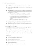
To begin our discussion, let’s look at the structure of a typical system
(Figure 36.1). The picture shows a single CPU attached to the main memory of the system via some kind of memory bus or interconnect. Some
devices are connected to the system via a general I/O bus, which in many
modern systems would be PCI (or one of its many derivatives); graphics and some other higher-performance I/O devices might be found here.
Finally, even lower down are one or more of what we call a peripheral
bus, such as SCSI, SATA, or USB. These connect the slowest devices to
the system, including disks, mice, and other similar components.
One question you might ask is: why do we need a hierarchical structure like this? Put simply: physics, and cost. The faster a bus is, the
shorter it must be; thus, a high-performance memory bus does not have
much room to plug devices and such into it. In addition, engineering
a bus for high performance is quite costly. Thus, system designers have
adopted this hierarchical approach, where components that demand high
performance (such as the graphics card) are nearer the CPU. Lower per1
2
I/O D EVICES
CPU
Memory
Memory Bus
(proprietary)
General I/O Bus
(e.g., PCI)
Graphics
Peripheral I/O Bus
(e.g., SCSI, SATA, USB)
Figure 36.1: Prototypical System Architecture
formance components are further away. The benefits of placing disks and
other slow devices on a peripheral bus are manifold; in particular, you
can place a large number of devices on it.
36.2
A Canonical Device
Let us now look at a canonical device (not a real one), and use this
device to drive our understanding of some of the machinery required
to make device interaction efficient. From Figure 36.2, we can see that a
device has two important components. The first is the hardware interface
it presents to the rest of the system. Just like a piece of software, hardware
must also present some kind of interface that allows the system software
to control its operation. Thus, all devices have some specified interface
and protocol for typical interaction.
The second part of any device is its internal structure. This part of
the device is implementation specific and is responsible for implementing the abstraction the device presents to the system. Very simple devices
will have one or a few hardware chips to implement their functionality;
more complex devices will include a simple CPU, some general purpose
memory, and other device-specific chips to get their job done. For example, modern RAID controllers might consist of hundreds of thousands of
lines of firmware (i.e., software within a hardware device) to implement
its functionality.
O PERATING
S YSTEMS
[V ERSION 0.90]
WWW. OSTEP. ORG
I/O D EVICES
3
Registers
Status
Command
Data
Micro-controller (CPU)
Memory (DRAM or SRAM or both)
Other Hardware-specific Chips
Interface
Internals
Figure 36.2: A Canonical Device
36.3 The Canonical Protocol
In the picture above, the (simplified) device interface is comprised of
three registers: a status register, which can be read to see the current status of the device; a command register, to tell the device to perform a certain task; and a data register to pass data to the device, or get data from
the device. By reading and writing these registers, the operating system
can control device behavior.
Let us now describe a typical interaction that the OS might have with
the device in order to get the device to do something on its behalf. The
protocol is as follows:
While (STATUS
; // wait
Write data to
Write command
(Doing so
While (STATUS
; // wait
== BUSY)
until device is not busy
DATA register
to COMMAND register
starts the device and executes the command)
== BUSY)
until device is done with your request
The protocol has four steps. In the first, the OS waits until the device is
ready to receive a command by repeatedly reading the status register; we
call this polling the device (basically, just asking it what is going on). Second, the OS sends some data down to the data register; one can imagine
that if this were a disk, for example, that multiple writes would need to
take place to transfer a disk block (say 4KB) to the device. When the main
CPU is involved with the data movement (as in this example protocol),
we refer to it as programmed I/O (PIO). Third, the OS writes a command
to the command register; doing so implicitly lets the device know that
both the data is present and that it should begin working on the command. Finally, the OS waits for the device to finish by again polling it
in a loop, waiting to see if it is finished (it may then get an error code to
indicate success or failure).
This basic protocol has the positive aspect of being simple and working. However, there are some inefficiencies and inconveniences involved.
The first problem you might notice in the protocol is that polling seems
inefficient; specifically, it wastes a great deal of CPU time just waiting for
the (potentially slow) device to complete its activity, instead of switching
to another ready process and thus better utilizing the CPU.
c 2014, A RPACI -D USSEAU
T HREE
E ASY
P IECES
4
I/O D EVICES
T HE C RUX : H OW T O AVOID T HE C OSTS O F P OLLING
How can the OS check device status without frequent polling, and
thus lower the CPU overhead required to manage the device?
36.4
Lowering CPU Overhead With Interrupts
The invention that many engineers came upon years ago to improve
this interaction is something we’ve seen already: the interrupt. Instead
of polling the device repeatedly, the OS can issue a request, put the calling process to sleep, and context switch to another task. When the device
is finally finished with the operation, it will raise a hardware interrupt,
causing the CPU to jump into the OS at a pre-determined interrupt service routine (ISR) or more simply an interrupt handler. The handler is
just a piece of operating system code that will finish the request (for example, by reading data and perhaps an error code from the device) and
wake the process waiting for the I/O, which can then proceed as desired.
Interrupts thus allow for overlap of computation and I/O, which is
key for improved utilization. This timeline shows the problem:
CPU
1
1
1
1
1
Disk
p
p
p
p
p
1
1
1
1
1
1
1
1
1
1
In the diagram, Process 1 runs on the CPU for some time (indicated by
a repeated 1 on the CPU line), and then issues an I/O request to the disk
to read some data. Without interrupts, the system simply spins, polling
the status of the device repeatedly until the I/O is complete (indicated by
a p). The disk services the request and finally Process 1 can run again.
If instead we utilize interrupts and allow for overlap, the OS can do
something else while waiting for the disk:
CPU
Disk
1
1
1
1
1
2
2
2
2
2
1
1
1
1
1
1
1
1
1
1
In this example, the OS runs Process 2 on the CPU while the disk services Process 1’s request. When the disk request is finished, an interrupt
occurs, and the OS wakes up Process 1 and runs it again. Thus, both the
CPU and the disk are properly utilized during the middle stretch of time.
Note that using interrupts is not always the best solution. For example,
imagine a device that performs its tasks very quickly: the first poll usually
finds the device to be done with task. Using an interrupt in this case will
actually slow down the system: switching to another process, handling the
interrupt, and switching back to the issuing process is expensive. Thus, if
a device is fast, it may be best to poll; if it is slow, interrupts, which allow
O PERATING
S YSTEMS
[V ERSION 0.90]
WWW. OSTEP. ORG
I/O D EVICES
5
T IP : I NTERRUPTS N OT A LWAYS B ETTER T HAN PIO
Although interrupts allow for overlap of computation and I/O, they only
really make sense for slow devices. Otherwise, the cost of interrupt handling and context switching may outweigh the benefits interrupts provide. There are also cases where a flood of interrupts may overload a system and lead it to livelock [MR96]; in such cases, polling provides more
control to the OS in its scheduling and thus is again useful.
overlap, are best. If the speed of the device is not known, or sometimes
fast and sometimes slow, it may be best to use a hybrid that polls for a
little while and then, if the device is not yet finished, uses interrupts. This
two-phased approach may achieve the best of both worlds.
Another reason not to use interrupts arises in networks [MR96]. When
a huge stream of incoming packets each generate an interrupt, it is possible for the OS to livelock, that is, find itself only processing interrupts
and never allowing a user-level process to run and actually service the
requests. For example, imagine a web server that suddenly experiences
a high load due to the “slashdot effect”. In this case, it is better to occasionally use polling to better control what is happening in the system and
allow the web server to service some requests before going back to the
device to check for more packet arrivals.
Another interrupt-based optimization is coalescing. In such a setup, a
device which needs to raise an interrupt first waits for a bit before delivering the interrupt to the CPU. While waiting, other requests may soon
complete, and thus multiple interrupts can be coalesced into a single interrupt delivery, thus lowering the overhead of interrupt processing. Of
course, waiting too long will increase the latency of a request, a common
trade-off in systems. See Ahmad et al. [A+11] for an excellent summary.
36.5 More Efficient Data Movement With DMA
Unfortunately, there is one other aspect of our canonical protocol that
requires our attention. In particular, when using programmed I/O (PIO)
to transfer a large chunk of data to a device, the CPU is once again overburdened with a rather trivial task, and thus wastes a lot of time and
effort that could better be spent running other processes. This timeline
illustrates the problem:
CPU
Disk
1
1
1
1
1
c
c
c
2
2
2
2
2
1
1
1
1
1
1
1
In the timeline, Process 1 is running and then wishes to write some data to
the disk. It then initiates the I/O, which must copy the data from memory
to the device explicitly, one word at a time (marked c in the diagram).
When the copy is complete, the I/O begins on the disk and the CPU can
finally be used for something else.
c 2014, A RPACI -D USSEAU
T HREE
E ASY
P IECES
6
I/O D EVICES
T HE C RUX : H OW T O L OWER PIO O VERHEADS
With PIO, the CPU spends too much time moving data to and from
devices by hand. How can we offload this work and thus allow the CPU
to be more effectively utilized?
The solution to this problem is something we refer to as Direct Memory Access (DMA). A DMA engine is essentially a very specific device
within a system that can orchestrate transfers between devices and main
memory without much CPU intervention.
DMA works as follows. To transfer data to the device, for example, the
OS would program the DMA engine by telling it where the data lives in
memory, how much data to copy, and which device to send it to. At that
point, the OS is done with the transfer and can proceed with other work.
When the DMA is complete, the DMA controller raises an interrupt, and
the OS thus knows the transfer is complete. The revised timeline:
CPU
DMA
1
1
1
1
1
2
2
2
c
c
c
Disk
2
2
2
2
2
1
1
1
1
1
1
1
From the timeline, you can see that the copying of data is now handled
by the DMA controller. Because the CPU is free during that time, the OS
can do something else, here choosing to run Process 2. Process 2 thus gets
to use more CPU before Process 1 runs again.
36.6
Methods Of Device Interaction
Now that we have some sense of the efficiency issues involved with
performing I/O, there are a few other problems we need to handle to
incorporate devices into modern systems. One problem you may have
noticed thus far: we have not really said anything about how the OS actually communicates with the device! Thus, the problem:
T HE C RUX : H OW T O C OMMUNICATE W ITH D EVICES
How should the hardware communicate with a device? Should there
be explicit instructions? Or are there other ways to do it?
Over time, two primary methods of device communication have developed. The first, oldest method (used by IBM mainframes for many
years) is to have explicit I/O instructions. These instructions specify a
way for the OS to send data to specific device registers and thus allow the
construction of the protocols described above.
O PERATING
S YSTEMS
[V ERSION 0.90]
WWW. OSTEP. ORG
I/O D EVICES
7
For example, on x86, the in and out instructions can be used to communicate with devices. For example, to send data to a device, the caller
specifies a register with the data in it, and a specific port which names the
device. Executing the instruction leads to the desired behavior.
Such instructions are usually privileged. The OS controls devices, and
the OS thus is the only entity allowed to directly communicate with them.
Imagine if any program could read or write the disk, for example: total
chaos (as always), as any user program could use such a loophole to gain
complete control over the machine.
The second method to interact with devices is known as memorymapped I/O. With this approach, the hardware makes device registers
available as if they were memory locations. To access a particular register,
the OS issues a load (to read) or store (to write) the address; the hardware
then routes the load/store to the device instead of main memory.
There is not some great advantage to one approach or the other. The
memory-mapped approach is nice in that no new instructions are needed
to support it, but both approaches are still in use today.
36.7 Fitting Into The OS: The Device Driver
One final problem we will discuss: how to fit devices, each of which
have very specific interfaces, into the OS, which we would like to keep
as general as possible. For example, consider a file system. We’d like
to build a file system that worked on top of SCSI disks, IDE disks, USB
keychain drives, and so forth, and we’d like the file system to be relatively
oblivious to all of the details of how to issue a read or write request to
these difference types of drives. Thus, our problem:
T HE C RUX : H OW T O B UILD A D EVICE - NEUTRAL OS
How can we keep most of the OS device-neutral, thus hiding the details of device interactions from major OS subsystems?
The problem is solved through the age-old technique of abstraction.
At the lowest level, a piece of software in the OS must know in detail
how a device works. We call this piece of software a device driver, and
any specifics of device interaction are encapsulated within.
Let us see how this abstraction might help OS design and implementation by examining the Linux file system software stack. Figure 36.3 is
a rough and approximate depiction of the Linux software organization.
As you can see from the diagram, a file system (and certainly, an application above) is completely oblivious to the specifics of which disk class
it is using; it simply issues block read and write requests to the generic
block layer, which routes them to the appropriate device driver, which
handles the details of issuing the specific request. Although simplified,
the diagram shows how such detail can be hidden from most of the OS.
c 2014, A RPACI -D USSEAU
T HREE
E ASY
P IECES
I/O D EVICES
user
8
Application
POSIX API [open, read, write, close, etc.]
Generic Block Interface [block read/write]
Generic Block Layer
Specific Block Interface [protocol-specific read/write]
kernel mode
File System
Device Driver [SCSI, ATA, etc.]
Figure 36.3: The File System Stack
Note that such encapsulation can have its downside as well. For example, if there is a device that has many special capabilities, but has to
present a generic interface to the rest of the kernel, those special capabilities will go unused. This situation arises, for example, in Linux with SCSI
devices, which have very rich error reporting; because other block devices (e.g., ATA/IDE) have much simpler error handling, all that higher
levels of software ever receive is a generic EIO (generic IO error) error
code; any extra detail that SCSI may have provided is thus lost to the file
system [G08].
Interestingly, because device drivers are needed for any device you
might plug into your system, over time they have come to represent a
huge percentage of kernel code. Studies of the Linux kernel reveal that
over 70% of OS code is found in device drivers [C01]; for Windows-based
systems, it is likely quite high as well. Thus, when people tell you that the
OS has millions of lines of code, what they are really saying is that the OS
has millions of lines of device-driver code. Of course, for any given installation, most of that code may not be active (i.e., only a few devices are
connected to the system at a time). Perhaps more depressingly, as drivers
are often written by “amateurs” (instead of full-time kernel developers),
they tend to have many more bugs and thus are a primary contributor to
kernel crashes [S03].
36.8
Case Study: A Simple IDE Disk Driver
To dig a little deeper here, let’s take a quick look at an actual device: an
IDE disk drive [L94]. We summarize the protocol as described in this reference [W10]; we’ll also peek at the xv6 source code for a simple example
of a working IDE driver [CK+08].
An IDE disk presents a simple interface to the system, consisting of
four types of register: control, command block, status, and error. These
registers are available by reading or writing to specific “I/O addresses”
(such as 0x3F6 below) using (on x86) the in and out I/O instructions.
O PERATING
S YSTEMS
[V ERSION 0.90]
WWW. OSTEP. ORG
I/O D EVICES
9
Control Register:
Address 0x3F6 = 0x80 (0000 1RE0): R=reset, E=0 means "enable interrupt"
Command Block Registers:
Address 0x1F0 = Data Port
Address 0x1F1 = Error
Address 0x1F2 = Sector Count
Address 0x1F3 = LBA low byte
Address 0x1F4 = LBA mid byte
Address 0x1F5 = LBA hi byte
Address 0x1F6 = 1B1D TOP4LBA: B=LBA, D=drive
Address 0x1F7 = Command/status
Status Register (Address 0x1F7):
7
6
5
4
3
2
1
0
BUSY READY FAULT SEEK DRQ CORR IDDEX ERROR
Error Register (Address 0x1F1): (check when Status ERROR==1)
7
6
5
4
3
2
1
0
BBK
UNC
MC
IDNF MCR ABRT T0NF AMNF
BBK
UNC
MC
IDNF
MCR
ABRT
T0NF
AMNF
=
=
=
=
=
=
=
=
Bad Block
Uncorrectable data error
Media Changed
ID mark Not Found
Media Change Requested
Command aborted
Track 0 Not Found
Address Mark Not Found
Figure 36.4: The IDE Interface
The basic protocol to interact with the device is as follows, assuming
it has already been initialized.
• Wait for drive to be ready. Read Status Register (0x1F7) until drive
is not busy and READY.
• Write parameters to command registers. Write the sector count,
logical block address (LBA) of the sectors to be accessed, and drive
number (master=0x00 or slave=0x10, as IDE permits just two drives)
to command registers (0x1F2-0x1F6).
• Start the I/O. by issuing read/write to command register. Write
READ—WRITE command to command register (0x1F7).
• Data transfer (for writes): Wait until drive status is READY and
DRQ (drive request for data); write data to data port.
• Handle interrupts. In the simplest case, handle an interrupt for
each sector transferred; more complex approaches allow batching
and thus one final interrupt when the entire transfer is complete.
• Error handling. After each operation, read the status register. If the
ERROR bit is on, read the error register for details.
Most of this protocol is found in the xv6 IDE driver (Figure 36.5),
which (after initialization) works through four primary functions. The
first is ide rw(), which queues a request (if there are others pending),
or issues it directly to the disk (via ide start request()); in either
c 2014, A RPACI -D USSEAU
T HREE
E ASY
P IECES
10
I/O D EVICES
static int ide_wait_ready() {
while (((int r = inb(0x1f7)) & IDE_BSY) || !(r & IDE_DRDY))
;
// loop until drive isn’t busy
}
static void ide_start_request(struct buf *b) {
ide_wait_ready();
outb(0x3f6, 0);
// generate interrupt
outb(0x1f2, 1);
// how many sectors?
outb(0x1f3, b->sector & 0xff);
// LBA goes here ...
outb(0x1f4, (b->sector >> 8) & 0xff);
// ... and here
outb(0x1f5, (b->sector >> 16) & 0xff); // ... and here!
outb(0x1f6, 0xe0 | ((b->dev&1)<<4) | ((b->sector>>24)&0x0f));
if(b->flags & B_DIRTY){
outb(0x1f7, IDE_CMD_WRITE);
// this is a WRITE
outsl(0x1f0, b->data, 512/4); // transfer data too!
} else {
outb(0x1f7, IDE_CMD_READ);
// this is a READ (no data)
}
}
void ide_rw(struct buf *b) {
acquire(&ide_lock);
for (struct buf **pp = &ide_queue; *pp; pp=&(*pp)->qnext)
;
// walk queue
// add request to end
*pp = b;
if (ide_queue == b)
// if q is empty
ide_start_request(b);
// send req to disk
while ((b->flags & (B_VALID|B_DIRTY)) != B_VALID)
sleep(b, &ide_lock);
// wait for completion
release(&ide_lock);
}
void ide_intr() {
struct buf *b;
acquire(&ide_lock);
if (!(b->flags & B_DIRTY) && ide_wait_ready() >= 0)
insl(0x1f0, b->data, 512/4);
// if READ: get data
b->flags |= B_VALID;
b->flags &= ˜B_DIRTY;
wakeup(b);
// wake waiting process
if ((ide_queue = b->qnext) != 0) // start next request
ide_start_request(ide_queue); // (if one exists)
release(&ide_lock);
}
Figure 36.5: The xv6 IDE Disk Driver (Simplified)
case, the routine waits for the request to complete and the calling process is put to sleep. The second is ide start request(), which is
used to send a request (and perhaps data, in the case of a write) to the
disk; the in and out x86 instructions are called to read and write device
registers, respectively. The start request routine uses the third function,
ide wait ready(), to ensure the drive is ready before issuing a request
to it. Finally, ide intr() is invoked when an interrupt takes place; it
reads data from the device (if the request is a read, not a write), wakes the
process waiting for the I/O to complete, and (if there are more requests
in the I/O queue), launches the next I/O via ide start request().
O PERATING
S YSTEMS
[V ERSION 0.90]
WWW. OSTEP. ORG
I/O D EVICES
11
36.9 Historical Notes
Before ending, we include a brief historical note on the origin of some
of these fundamental ideas. If you are interested in learning more, read
Smotherman’s excellent summary [S08].
Interrupts are an ancient idea, existing on the earliest of machines. For
example, the UNIVAC in the early 1950’s had some form of interrupt vectoring, although it is unclear in exactly which year this feature was available [S08]. Sadly, even in its infancy, we are beginning to lose the origins
of computing history.
There is also some debate as to which machine first introduced the idea
of DMA. For example, Knuth and others point to the DYSEAC (a “mobile” machine, which at the time meant it could be hauled in a trailer),
whereas others think the IBM SAGE may have been the first [S08]. Either way, by the mid 50’s, systems with I/O devices that communicated
directly with memory and interrupted the CPU when finished existed.
The history here is difficult to trace because the inventions are tied to
real, and sometimes obscure, machines. For example, some think that the
Lincoln Labs TX-2 machine was first with vectored interrupts [S08], but
this is hardly clear.
Because the ideas are relatively obvious — no Einsteinian leap is required to come up with the idea of letting the CPU do something else
while a slow I/O is pending — perhaps our focus on “who first?” is misguided. What is certainly clear: as people built these early machines, it
became obvious that I/O support was needed. Interrupts, DMA, and related ideas are all direct outcomes of the nature of fast CPUs and slow
devices; if you were there at the time, you might have had similar ideas.
36.10 Summary
You should now have a very basic understanding of how an OS interacts with a device. Two techniques, the interrupt and DMA, have been
introduced to help with device efficiency, and two approaches to accessing device registers, explicit I/O instructions and memory-mapped I/O,
have been described. Finally, the notion of a device driver has been presented, showing how the OS itself can encapsulate low-level details and
thus make it easier to build the rest of the OS in a device-neutral fashion.
c 2014, A RPACI -D USSEAU
T HREE
E ASY
P IECES
12
I/O D EVICES
References
[A+11] “vIC: Interrupt Coalescing for Virtual Machine Storage Device IO”
Irfan Ahmad, Ajay Gulati, Ali Mashtizadeh
USENIX ’11
A terrific survey of interrupt coalescing in traditional and virtualized environments.
[C01] “An Empirical Study of Operating System Errors”
Andy Chou, Junfeng Yang, Benjamin Chelf, Seth Hallem, Dawson Engler
SOSP ’01
One of the first papers to systematically explore how many bugs are in modern operating systems.
Among other neat findings, the authors show that device drivers have something like seven times more
bugs than mainline kernel code.
[CK+08] “The xv6 Operating System”
Russ Cox, Frans Kaashoek, Robert Morris, Nickolai Zeldovich
From: />See ide.c for the IDE device driver, with a few more details therein.
[D07] “What Every Programmer Should Know About Memory”
Ulrich Drepper
November, 2007
Available: />A fantastic read about modern memory systems, starting at DRAM and going all the way up to virtualization and cache-optimized algorithms.
[G08] “EIO: Error-handling is Occasionally Correct”
Haryadi Gunawi, Cindy Rubio-Gonzalez, Andrea Arpaci-Dusseau, Remzi Arpaci-Dusseau,
Ben Liblit
FAST ’08, San Jose, CA, February 2008
Our own work on building a tool to find code in Linux file systems that does not handle error return
properly. We found hundreds and hundreds of bugs, many of which have now been fixed.
[L94] “AT Attachment Interface for Disk Drives”
Lawrence J. Lamers, X3T10 Technical Editor
Available: />Reference number: ANSI X3.221 - 1994 A rather dry document about device interfaces. Read it at
your own peril.
[MR96] “Eliminating Receive Livelock in an Interrupt-driven Kernel”
Jeffrey Mogul and K. K. Ramakrishnan
USENIX ’96, San Diego, CA, January 1996
Mogul and colleagues did a great deal of pioneering work on web server network performance. This
paper is but one example.
[S08] “Interrupts”
Mark Smotherman, as of July ’08
Available: />A treasure trove of information on the history of interrupts, DMA, and related early ideas in computing.
O PERATING
S YSTEMS
[V ERSION 0.90]
WWW. OSTEP. ORG
I/O D EVICES
13
[S03] “Improving the Reliability of Commodity Operating Systems”
Michael M. Swift, Brian N. Bershad, and Henry M. Levy
SOSP ’03
Swift’s work revived interest in a more microkernel-like approach to operating systems; minimally, it
finally gave some good reasons why address-space based protection could be useful in a modern OS.
[W10] “Hard Disk Driver”
Washington State Course Homepage
Available: />A nice summary of a simple IDE disk drive’s interface and how to build a device driver for it.
c 2014, A RPACI -D USSEAU
T HREE
E ASY
P IECES