File System Implementation
Bạn đang xem bản rút gọn của tài liệu. Xem và tải ngay bản đầy đủ của tài liệu tại đây (161.46 KB, 18 trang )
40
File System Implementation
In this chapter, we introduce a simple file system implementation, known
as vsfs (the Very Simple File System). This file system is a simplified
version of a typical U NIX file system and thus serves to introduce some
of the basic on-disk structures, access methods, and various policies that
you will find in many file systems today.
The file system is pure software; unlike our development of CPU and
memory virtualization, we will not be adding hardware features to make
some aspect of the file system work better (though we will want to pay attention to device characteristics to make sure the file system works well).
Because of the great flexibility we have in building a file system, many
different ones have been built, literally from AFS (the Andrew File System) [H+88] to ZFS (Sun’s Zettabyte File System) [B07]. All of these file
systems have different data structures and do some things better or worse
than their peers. Thus, the way we will be learning about file systems is
through case studies: first, a simple file system (vsfs) in this chapter to
introduce most concepts, and then a series of studies of real file systems
to understand how they can differ in practice.
T HE C RUX : H OW T O I MPLEMENT A S IMPLE F ILE S YSTEM
How can we build a simple file system? What structures are needed
on the disk? What do they need to track? How are they accessed?
40.1 The Way To Think
To think about file systems, we usually suggest thinking about two
different aspects of them; if you understand both of these aspects, you
probably understand how the file system basically works.
The first is the data structures of the file system. In other words, what
types of on-disk structures are utilized by the file system to organize its
data and metadata? The first file systems we’ll see (including vsfs below)
employ simple structures, like arrays of blocks or other objects, whereas
1
2
F ILE S YSTEM I MPLEMENTATION
A SIDE : M ENTAL M ODELS O F F ILE S YSTEMS
As we’ve discussed before, mental models are what you are really trying
to develop when learning about systems. For file systems, your mental
model should eventually include answers to questions like: what on-disk
structures store the file system’s data and metadata? What happens when
a process opens a file? Which on-disk structures are accessed during a
read or write? By working on and improving your mental model, you
develop an abstract understanding of what is going on, instead of just
trying to understand the specifics of some file-system code (though that
is also useful, of course!).
more sophisticated file systems, like SGI’s XFS, use more complicated
tree-based structures [S+96].
The second aspect of a file system is its access methods. How does
it map the calls made by a process, such as open(), read(), write(),
etc., onto its structures? Which structures are read during the execution
of a particular system call? Which are written? How efficiently are all of
these steps performed?
If you understand the data structures and access methods of a file system, you have developed a good mental model of how it truly works, a
key part of the systems mindset. Try to work on developing your mental
model as we delve into our first implementation.
40.2
Overall Organization
We now develop the overall on-disk organization of the data structures of the vsfs file system. The first thing we’ll need to do is divide the
disk into blocks; simple file systems use just one block size, and that’s
exactly what we’ll do here. Let’s choose a commonly-used size of 4 KB.
Thus, our view of the disk partition where we’re building our file system is simple: a series of blocks, each of size 4 KB. The blocks are addressed from 0 to N − 1, in a partition of size N 4-KB blocks. Assume we
have a really small disk, with just 64 blocks:
0
7 8
15 16
23 24
31
32
39 40
47 48
55 56
63
Let’s now think about what we need to store in these blocks to build
a file system. Of course, the first thing that comes to mind is user data.
In fact, most of the space in any file system is (and should be) user data.
Let’s call the region of the disk we use for user data the data region, and,
O PERATING
S YSTEMS
[V ERSION 0.90]
WWW. OSTEP. ORG
F ILE S YSTEM I MPLEMENTATION
3
again for simplicity, reserve a fixed portion of the disk for these blocks,
say the last 56 of 64 blocks on the disk:
Data Region
DDDDDDDD DDDDDDDD
0
7 8
15 16
23
Data Region
DDDDDDDD DDDDDDDD DDDDDDDD
32
39 40
47 48
55
DDDDDDDD
24
31
DDDDDDDD
56
63
As we learned about (a little) last chapter, the file system has to track
information about each file. This information is a key piece of metadata,
and tracks things like which data blocks (in the data region) comprise a
file, the size of the file, its owner and access rights, access and modify
times, and other similar kinds of information. To store this information,
file systems usually have a structure called an inode (we’ll read more
about inodes below).
To accommodate inodes, we’ll need to reserve some space on the disk
for them as well. Let’s call this portion of the disk the inode table, which
simply holds an array of on-disk inodes. Thus, our on-disk image now
looks like this picture, assuming that we use 5 of our 64 blocks for inodes
(denoted by I’s in the diagram):
Data Region
Inodes
DDDDDDDD DDDDDDDD
0
7 8
15 16
23
Data Region
DDDDDDDD DDDDDDDD DDDDDDDD
32
39 40
47 48
55
I
I
I
I
I
DDDDDDDD
24
31
DDDDDDDD
56
63
We should note here that inodes are typically not that big, for example
128 or 256 bytes. Assuming 256 bytes per inode, a 4-KB block can hold 16
inodes, and our file system above contains 80 total inodes. In our simple
file system, built on a tiny 64-block partition, this number represents the
maximum number of files we can have in our file system; however, do
note that the same file system, built on a larger disk, could simply allocate
a larger inode table and thus accommodate more files.
Our file system thus far has data blocks (D), and inodes (I), but a few
things are still missing. One primary component that is still needed, as
you might have guessed, is some way to track whether inodes or data
blocks are free or allocated. Such allocation structures are thus a requisite
element in any file system.
Many allocation-tracking methods are possible, of course. For example, we could use a free list that points to the first free block, which then
points to the next free block, and so forth. We instead choose a simple and
popular structure known as a bitmap, one for the data region (the data
bitmap), and one for the inode table (the inode bitmap). A bitmap is a
c 2014, A RPACI -D USSEAU
T HREE
E ASY
P IECES
4
F ILE S YSTEM I MPLEMENTATION
simple structure: each bit is used to indicate whether the corresponding
object/block is free (0) or in-use (1). And thus our new on-disk layout,
with an inode bitmap (i) and a data bitmap (d):
Data Region
Inodes
i d
DDDDDDDD DDDDDDDD
7 8
0
15 16
23
Data Region
DDDDDDDD DDDDDDDD DDDDDDDD
32
39 40
47 48
55
I
I
I
I
I
DDDDDDDD
24
31
DDDDDDDD
56
63
You may notice that it is a bit of overkill to use an entire 4-KB block for
these bitmaps; such a bitmap can track whether 32K objects are allocated,
and yet we only have 80 inodes and 56 data blocks. However, we just use
an entire 4-KB block for each of these bitmaps for simplicity.
The careful reader (i.e., the reader who is still awake) may have noticed there is one block left in the design of the on-disk structure of our
very simple file system. We reserve this for the superblock, denoted by
an S in the diagram below. The superblock contains information about
this particular file system, including, for example, how many inodes and
data blocks are in the file system (80 and 56, respectively in this instance),
where the inode table begins (block 3), and so forth. It will likely also
include a magic number of some kind to identify the file system type (in
this case, vsfs).
Inodes
S i d
0
Data Region
DDDDDDDD DDDDDDDD
7 8
15 16
23
Data Region
DDDDDDDD DDDDDDDD DDDDDDDD
32
39 40
47 48
55
I
I
I
I
I
DDDDDDDD
24
31
DDDDDDDD
56
63
Thus, when mounting a file system, the operating system will read
the superblock first, to initialize various parameters, and then attach the
volume to the file-system tree. When files within the volume are accessed,
the system will thus know exactly where to look for the needed on-disk
structures.
40.3
File Organization: The Inode
One of the most important on-disk structures of a file system is the
inode; virtually all file systems have a structure similar to this. The name
inode is short for index node, the historical name given to it by U NIX inventor Ken Thompson [RT74], used because these nodes were originally
arranged in an array, and the array indexed into when accessing a particular inode.
O PERATING
S YSTEMS
[V ERSION 0.90]
WWW. OSTEP. ORG
F ILE S YSTEM I MPLEMENTATION
5
A SIDE : D ATA S TRUCTURE — T HE I NODE
The inode is the generic name that is used in many file systems to describe the structure that holds the metadata for a given file, such as its
length, permissions, and the location of its constituent blocks. The name
goes back at least as far as U NIX (and probably further back to Multics
if not earlier systems); it is short for index node, as the inode number is
used to index into an array of on-disk inodes in order to find the inode
of that number. As we’ll see, design of the inode is one key part of file
system design. Most modern systems have some kind of structure like
this for every file they track, but perhaps call them different things (such
as dnodes, fnodes, etc.).
Each inode is implicitly referred to by a number (called the inumber),
which we’ve earlier called the low-level name of the file. In vsfs (and
other simple file systems), given an i-number, you should directly be able
to calculate where on the disk the corresponding inode is located. For example, take the inode table of vsfs as above: 20-KB in size (5 4-KB blocks)
and thus consisting of 80 inodes (assuming each inode is 256 bytes); further assume that the inode region starts at 12KB (i.e, the superblock starts
at 0KB, the inode bitmap is at address 4KB, the data bitmap at 8KB, and
thus the inode table comes right after). In vsfs, we thus have the following
layout for the beginning of the file system partition (in closeup view):
The Inode Table (Closeup)
iblock 0
Super
i-bmap d-bmap
iblock 1
iblock 2
iblock 3
iblock 4
0
1
2
3 16 17 18 19 32 33 34 35 48 49 50 51 64 65 66 67
4
5
6
7 20 21 22 23 36 37 38 39 52 53 54 55 68 69 70 71
8
9 10 11 24 25 26 27 40 41 42 43 56 57 58 59 72 73 74 75
12 13 14 15 28 29 30 31 44 45 46 47 60 61 62 63 76 77 78 79
0KB
4KB
8KB
12KB
16KB
20KB
24KB
28KB
32KB
To read inode number 32, the file system would first calculate the offset into the inode region (32 · sizeof (inode) or 8192), add it to the start
address of the inode table on disk (inodeStartAddr = 12KB), and thus
arrive upon the correct byte address of the desired block of inodes: 20KB.
Recall that disks are not byte addressable, but rather consist of a large
number of addressable sectors, usually 512 bytes. Thus, to fetch the block
of inodes that contains inode 32, the file system would issue a read to sector 20×1024
, or 40, to fetch the desired inode block. More generally, the
512
sector address iaddr of the inode block can be calculated as follows:
blk
= (inumber * sizeof(inode_t)) / blockSize;
sector = ((blk * blockSize) + inodeStartAddr) / sectorSize;
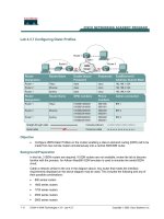
Inside each inode is virtually all of the information you need about a
file: its type (e.g., regular file, directory, etc.), its size, the number of blocks
c 2014, A RPACI -D USSEAU
T HREE
E ASY
P IECES
6
F ILE S YSTEM I MPLEMENTATION
Size
2
2
4
4
4
4
4
2
2
4
4
4
60
4
4
4
4
12
Name
mode
uid
size
time
ctime
mtime
dtime
gid
links count
blocks
flags
osd1
block
generation
file acl
dir acl
faddr
i osd2
What is this inode field for?
can this file be read/written/executed?
who owns this file?
how many bytes are in this file?
what time was this file last accessed?
what time was this file created?
what time was this file last modified?
what time was this inode deleted?
which group does this file belong to?
how many hard links are there to this file?
how many blocks have been allocated to this file?
how should ext2 use this inode?
an OS-dependent field
a set of disk pointers (15 total)
file version (used by NFS)
a new permissions model beyond mode bits
called access control lists
an unsupported field
another OS-dependent field
Figure 40.1: The Ext2 Inode
allocated to it, protection information (such as who owns the file, as well
as who can access it), some time information, including when the file was
created, modified, or last accessed, as well as information about where its
data blocks reside on disk (e.g., pointers of some kind). We refer to all
such information about a file as metadata; in fact, any information inside
the file system that isn’t pure user data is often referred to as such. An
example inode from ext2 [P09] is shown in Figure 40.1.
One of the most important decisions in the design of the inode is how
it refers to where data blocks are. One simple approach would be to
have one or more direct pointers (disk addresses) inside the inode; each
pointer refers to one disk block that belongs to the file. Such an approach
is limited: for example, if you want to have a file that is really big (e.g.,
bigger than the size of a block multiplied by the number of direct pointers), you are out of luck.
The Multi-Level Index
To support bigger files, file system designers have had to introduce different structures within inodes. One common idea is to have a special
pointer known as an indirect pointer. Instead of pointing to a block that
contains user data, it points to a block that contains more pointers, each
of which point to user data. Thus, an inode may have some fixed number
of direct pointers (e.g., 12), and a single indirect pointer. If a file grows
large enough, an indirect block is allocated (from the data-block region
of the disk), and the inode’s slot for an indirect pointer is set to point to
it. Assuming that a block is 4KB and 4-byte disk addresses, that adds
another 1024 pointers; the file can grow to be (12 + 1024) · 4K or 4144KB.
O PERATING
S YSTEMS
[V ERSION 0.90]
WWW. OSTEP. ORG
F ILE S YSTEM I MPLEMENTATION
7
T IP : C ONSIDER E XTENT- BASED A PPROACHES
A different approach is to use extents instead of pointers. An extent is
simply a disk pointer plus a length (in blocks); thus, instead of requiring
a pointer for every block of a file, all one needs is a pointer and a length
to specify the on-disk location of a file. Just a single extent is limiting, as
one may have trouble finding a contiguous chunk of on-disk free space
when allocating a file. Thus, extent-based file systems often allow for
more than one extent, thus giving more freedom to the file system during
file allocation.
In comparing the two approaches, pointer-based approaches are the most
flexible but use a large amount of metadata per file (particularly for large
files). Extent-based approaches are less flexible but more compact; in particular, they work well when there is enough free space on the disk and
files can be laid out contiguously (which is the goal for virtually any file
allocation policy anyhow).
Not surprisingly, in such an approach, you might want to support
even larger files. To do so, just add another pointer to the inode: the double indirect pointer. This pointer refers to a block that contains pointers
to indirect blocks, each of which contain pointers to data blocks. A double indirect block thus adds the possibility to grow files with an additional
1024 · 1024 or 1-million 4KB blocks, in other words supporting files that
are over 4GB in size. You may want even more, though, and we bet you
know where this is headed: the triple indirect pointer.
Overall, this imbalanced tree is referred to as the multi-level index approach to pointing to file blocks. Let’s examine an example with twelve
direct pointers, as well as both a single and a double indirect block. Assuming a block size of 4 KB, and 4-byte pointers, this structure can accommodate a file of just over 4 GB in size (i.e., (12 + 1024 + 10242 ) × 4 KB).
Can you figure out how big of a file can be handled with the addition of
a triple-indirect block? (hint: pretty big)
Many file systems use a multi-level index, including commonly-used
file systems such as Linux ext2 [P09] and ext3, NetApp’s WAFL, as well as
the original U NIX file system. Other file systems, including SGI XFS and
Linux ext4, use extents instead of simple pointers; see the earlier aside for
details on how extent-based schemes work (they are akin to segments in
the discussion of virtual memory).
You might be wondering: why use an imbalanced tree like this? Why
not a different approach? Well, as it turns out, many researchers have
studied file systems and how they are used, and virtually every time they
find certain “truths” that hold across the decades. One such finding is
that most files are small. This imbalanced design reflects such a reality; if
most files are indeed small, it makes sense to optimize for this case. Thus,
with a small number of direct pointers (12 is a typical number), an inode
c 2014, A RPACI -D USSEAU
T HREE
E ASY
P IECES
8
F ILE S YSTEM I MPLEMENTATION
A SIDE : L INKED - BASED A PPROACHES
Another simpler approach in designing inodes is to use a linked list.
Thus, inside an inode, instead of having multiple pointers, you just need
one, to point to the first block of the file. To handle larger files, add another pointer at the end of that data block, and so on, and thus you can
support large files.
As you might have guessed, linked file allocation performs poorly for
some workloads; think about reading the last block of a file, for example,
or just doing random access. Thus, to make linked allocation work better,
some systems will keep an in-memory table of link information, instead
of storing the next pointers with the data blocks themselves. The table
is indexed by the address of a data block D; the content of an entry is
simply D’s next pointer, i.e., the address of the next block in a file which
follows D. A null-value could be there too (indicating an end-of-file), or
some other marker to indicate that a particular block is free. Having such
a table of next pointers makes it so that a linked allocation scheme can
effectively do random file accesses, simply by first scanning through the
(in memory) table to find the desired block, and then accessing (on disk)
it directly.
Does such a table sound familiar? What we have described is the basic
structure of what is known as the file allocation table, or FAT file system.
Yes, this classic old Windows file system, before NTFS [C94], is based on a
simple linked-based allocation scheme. There are other differences from
a standard U NIX file system too; for example, there are no inodes per se,
but rather directory entries which store metadata about a file and refer
directly to the first block of said file, which makes creating hard links
impossible. See Brouwer [B02] for more of the inelegant details.
can directly point to 48 KB of data, needing one (or more) indirect blocks
for larger files. See Agrawal et. al [A+07] for a recent study; Figure 40.2
summarizes those results.
Of course, in the space of inode design, many other possibilities exist; after all, the inode is just a data structure, and any data structure that
stores the relevant information, and can query it effectively, is sufficient.
As file system software is readily changed, you should be willing to explore different designs should workloads or technologies change.
Most files are small
Average file size is growing
Most bytes are stored in large files
File systems contains lots of files
File systems are roughly half full
Directories are typically small
Roughly 2K is the most common size
Almost 200K is the average
A few big files use most of the space
Almost 100K on average
Even as disks grow, file systems remain ˜50% full
Many have few entries; most have 20 or fewer
Figure 40.2: File System Measurement Summary
O PERATING
S YSTEMS
[V ERSION 0.90]
WWW. OSTEP. ORG
F ILE S YSTEM I MPLEMENTATION
9
40.4 Directory Organization
In vsfs (as in many file systems), directories have a simple organization; a directory basically just contains a list of (entry name, inode number) pairs. For each file or directory in a given directory, there is a string
and a number in the data block(s) of the directory. For each string, there
may also be a length (assuming variable-sized names).
For example, assume a directory dir (inode number 5) has three files
in it (foo, bar, and foobar), and their inode numbers are 12, 13, and 24
respectively. The on-disk data for dir might look like this:
inum | reclen | strlen | name
5
4
2
.
2
4
3
..
12
4
4
foo
13
4
4
bar
24
8
7
foobar
In this example, each entry has an inode number, record length (the
total bytes for the name plus any left over space), string length (the actual
length of the name), and finally the name of the entry. Note that each directory has two extra entries, . “dot” and .. “dot-dot”; the dot directory
is just the current directory (in this example, dir), whereas dot-dot is the
parent directory (in this case, the root).
Deleting a file (e.g., calling unlink()) can leave an empty space in
the middle of the directory, and hence there should be some way to mark
that as well (e.g., with a reserved inode number such as zero). Such a
delete is one reason the record length is used: a new entry may reuse an
old, bigger entry and thus have extra space within.
You might be wondering where exactly directories are stored. Often,
file systems treat directories as a special type of file. Thus, a directory has
an inode, somewhere in the inode table (with the type field of the inode
marked as “directory” instead of “regular file”). The directory has data
blocks pointed to by the inode (and perhaps, indirect blocks); these data
blocks live in the data block region of our simple file system. Our on-disk
structure thus remains unchanged.
We should also note again that this simple linear list of directory entries is not the only way to store such information. As before, any data
structure is possible. For example, XFS [S+96] stores directories in B-tree
form, making file create operations (which have to ensure that a file name
has not been used before creating it) faster than systems with simple lists
that must be scanned in their entirety.
40.5 Free Space Management
A file system must track which inodes and data blocks are free, and
which are not, so that when a new file or directory is allocated, it can find
space for it. Thus free space management is important for all file systems.
In vsfs, we have two simple bitmaps for this task.
c 2014, A RPACI -D USSEAU
T HREE
E ASY
P IECES
10
F ILE S YSTEM I MPLEMENTATION
A SIDE : F REE S PACE M ANAGEMENT
There are many ways to manage free space; bitmaps are just one way.
Some early file systems used free lists, where a single pointer in the super
block was kept to point to the first free block; inside that block the next
free pointer was kept, thus forming a list through the free blocks of the
system. When a block was needed, the head block was used and the list
updated accordingly.
Modern file systems use more sophisticated data structures. For example,
SGI’s XFS [S+96] uses some form of a B-tree to compactly represent which
chunks of the disk are free. As with any data structure, different timespace trade-offs are possible.
For example, when we create a file, we will have to allocate an inode
for that file. The file system will thus search through the bitmap for an inode that is free, and allocate it to the file; the file system will have to mark
the inode as used (with a 1) and eventually update the on-disk bitmap
with the correct information. A similar set of activities take place when a
data block is allocated.
Some other considerations might also come into play when allocating
data blocks for a new file. For example, some Linux file systems, such
as ext2 and ext3, will look for a sequence of blocks (say 8) that are free
when a new file is created and needs data blocks; by finding such a sequence of free blocks, and then allocating them to the newly-created file,
the file system guarantees that a portion of the file will be on the disk and
contiguous, thus improving performance. Such a pre-allocation policy is
thus a commonly-used heuristic when allocating space for data blocks.
40.6
Access Paths: Reading and Writing
Now that we have some idea of how files and directories are stored on
disk, we should be able to follow the flow of operation during the activity
of reading or writing a file. Understanding what happens on this access
path is thus the second key in developing an understanding of how a file
system works; pay attention!
For the following examples, let us assume that the file system has been
mounted and thus that the superblock is already in memory. Everything
else (i.e., inodes, directories) is still on the disk.
Reading A File From Disk
In this simple example, let us first assume that you want to simply open
a file (e.g., /foo/bar, read it, and then close it. For this simple example,
let’s assume the file is just 4KB in size (i.e., 1 block).
When you issue an open("/foo/bar", O RDONLY) call, the file system first needs to find the inode for the file bar, to obtain some basic information about the file (permissions information, file size, etc.). To do so,
O PERATING
S YSTEMS
[V ERSION 0.90]
WWW. OSTEP. ORG
F ILE S YSTEM I MPLEMENTATION
11
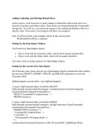
data
inode root
foo
bar root foo
bar
bar
bar
bitmap bitmap inode inode inode data data data[0] data[1] data[2]
read
read
open(bar)
read
read
read
read
read()
read
write
read
read()
read
write
read
read()
read
write
Figure 40.3: File Read Timeline (Time Increasing Downward)
the file system must be able to find the inode, but all it has right now is
the full pathname. The file system must traverse the pathname and thus
locate the desired inode.
All traversals begin at the root of the file system, in the root directory
which is simply called /. Thus, the first thing the FS will read from disk
is the inode of the root directory. But where is this inode? To find an
inode, we must know its i-number. Usually, we find the i-number of a file
or directory in its parent directory; the root has no parent (by definition).
Thus, the root inode number must be “well known”; the FS must know
what it is when the file system is mounted. In most U NIX file systems,
the root inode number is 2. Thus, to begin the process, the FS reads in the
block that contains inode number 2 (the first inode block).
Once the inode is read in, the FS can look inside of it to find pointers to
data blocks, which contain the contents of the root directory. The FS will
thus use these on-disk pointers to read through the directory, in this case
looking for an entry for foo. By reading in one or more directory data
blocks, it will find the entry for foo; once found, the FS will also have
found the inode number of foo (say it is 44) which it will need next.
The next step is to recursively traverse the pathname until the desired
inode is found. In this example, the FS reads the block containing the
inode of foo and then its directory data, finally finding the inode number
of bar. The final step of open() is to read bar’s inode into memory; the
FS then does a final permissions check, allocates a file descriptor for this
process in the per-process open-file table, and returns it to the user.
Once open, the program can then issue a read() system call to read
from the file. The first read (at offset 0 unless lseek() has been called)
will thus read in the first block of the file, consulting the inode to find
the location of such a block; it may also update the inode with a new lastaccessed time. The read will further update the in-memory open file table
for this file descriptor, updating the file offset such that the next read will
read the second file block, etc.
c 2014, A RPACI -D USSEAU
T HREE
E ASY
P IECES
12
F ILE S YSTEM I MPLEMENTATION
A SIDE : R EADS D ON ’ T A CCESS A LLOCATION S TRUCTURES
We’ve seen many students get confused by allocation structures such
as bitmaps. In particular, many often think that when you are simply
reading a file, and not allocating any new blocks, that the bitmap will still
be consulted. This is not true! Allocation structures, such as bitmaps,
are only accessed when allocation is needed. The inodes, directories, and
indirect blocks have all the information they need to complete a read request; there is no need to make sure a block is allocated when the inode
already points to it.
At some point, the file will be closed. There is much less work to be
done here; clearly, the file descriptor should be deallocated, but for now,
that is all the FS really needs to do. No disk I/Os take place.
A depiction of this entire process is found in Figure 40.3 (time increases
downward). In the figure, the open causes numerous reads to take place
in order to finally locate the inode of the file. Afterwards, reading each
block requires the file system to first consult the inode, then read the
block, and then update the inode’s last-accessed-time field with a write.
Spend some time and try to understand what is going on.
Also note that the amount of I/O generated by the open is proportional to the length of the pathname. For each additional directory in the
path, we have to read its inode as well as its data. Making this worse
would be the presence of large directories; here, we only have to read one
block to get the contents of a directory, whereas with a large directory, we
might have to read many data blocks to find the desired entry. Yes, life
can get pretty bad when reading a file; as you’re about to find out, writing
out a file (and especially, creating a new one) is even worse.
Writing to Disk
Writing to a file is a similar process. First, the file must be opened (as
above). Then, the application can issue write() calls to update the file
with new contents. Finally, the file is closed.
Unlike reading, writing to the file may also allocate a block (unless
the block is being overwritten, for example). When writing out a new
file, each write not only has to write data to disk but has to first decide
which block to allocate to the file and thus update other structures of the
disk accordingly (e.g., the data bitmap and inode). Thus, each write to a
file logically generates five I/Os: one to read the data bitmap (which is
then updated to mark the newly-allocated block as used), one to write the
bitmap (to reflect its new state to disk), two more to read and then write
the inode (which is updated with the new block’s location), and finally
one to write the actual block itself.
The amount of write traffic is even worse when one considers a simple and common operation such as file creation. To create a file, the file
system must not only allocate an inode, but also allocate space within
O PERATING
S YSTEMS
[V ERSION 0.90]
WWW. OSTEP. ORG
F ILE S YSTEM I MPLEMENTATION
13
data
inode root foo
bar root foo
bar
bar
bar
bitmap bitmap inode inode inode data data data[0] data[1] data[2]
read
read
read
read
create
read
(/foo/bar)
write
write
read
write
write
read
read
write()
write
write
write
read
read
write()
write
write
write
read
read
write()
write
write
write
Figure 40.4: File Creation Timeline (Time Increasing Downward)
the directory containing the new file. The total amount of I/O traffic to
do so is quite high: one read to the inode bitmap (to find a free inode),
one write to the inode bitmap (to mark it allocated), one write to the new
inode itself (to initialize it), one to the data of the directory (to link the
high-level name of the file to its inode number), and one read and write
to the directory inode to update it. If the directory needs to grow to accommodate the new entry, additional I/Os (i.e., to the data bitmap, and
the new directory block) will be needed too. All that just to create a file!
Let’s look at a specific example, where the file /foo/bar is created,
and three blocks are written to it. Figure 40.4 shows what happens during
the open() (which creates the file) and during each of three 4KB writes.
In the figure, reads and writes to the disk are grouped under which
system call caused them to occur, and the rough ordering they might take
place in goes from top to bottom of the figure. You can see how much
work it is to create the file: 10 I/Os in this case, to walk the pathname
and then finally create the file. You can also see that each allocating write
costs 5 I/Os: a pair to read and update the inode, another pair to read
and update the data bitmap, and then finally the write of the data itself.
How can a file system accomplish any of this with reasonable efficiency?
c 2014, A RPACI -D USSEAU
T HREE
E ASY
P IECES
14
F ILE S YSTEM I MPLEMENTATION
T HE C RUX : H OW T O R EDUCE F ILE S YSTEM I/O C OSTS
Even the simplest of operations like opening, reading, or writing a file
incurs a huge number of I/O operations, scattered over the disk. What
can a file system do to reduce the high costs of doing so many I/Os?
40.7
Caching and Buffering
As the examples above show, reading and writing files can be expensive, incurring many I/Os to the (slow) disk. To remedy what would
clearly be a huge performance problem, most file systems aggressively
use system memory (DRAM) to cache important blocks.
Imagine the open example above: without caching, every file open
would require at least two reads for every level in the directory hierarchy
(one to read the inode of the directory in question, and at least one to read
its data). With a long pathname (e.g., /1/2/3/ ... /100/file.txt), the file
system would literally perform hundreds of reads just to open the file!
Early file systems thus introduced a fixed-size cache to hold popular
blocks. As in our discussion of virtual memory, strategies such as LRU
and different variants would decide which blocks to keep in cache. This
fixed-size cache would usually be allocated at boot time to be roughly
10% of total memory.
This static partitioning of memory, however, can be wasteful; what
if the file system doesn’t need 10% of memory at a given point in time?
With the fixed-size approach described above, unused pages in the file
cache cannot be re-purposed for some other use, and thus go to waste.
Modern systems, in contrast, employ a dynamic partitioning approach.
Specifically, many modern operating systems integrate virtual memory
pages and file system pages into a unified page cache [S00]. In this way,
memory can be allocated more flexibly across virtual memory and file
system, depending on which needs more memory at a given time.
Now imagine the file open example with caching. The first open may
generate a lot of I/O traffic to read in directory inode and data, but subsequent file opens of that same file (or files in the same directory) will
mostly hit in the cache and thus no I/O is needed.
Let us also consider the effect of caching on writes. Whereas read I/O
can be avoided altogether with a sufficiently large cache, write traffic has
to go to disk in order to become persistent. Thus, a cache does not serve
as the same kind of filter on write traffic that it does for reads. That said,
write buffering (as it is sometimes called) certainly has a number of performance benefits. First, by delaying writes, the file system can batch
some updates into a smaller set of I/Os; for example, if an inode bitmap
is updated when one file is created and then updated moments later as
another file is created, the file system saves an I/O by delaying the write
after the first update. Second, by buffering a number of writes in memory,
O PERATING
S YSTEMS
[V ERSION 0.90]
WWW. OSTEP. ORG
F ILE S YSTEM I MPLEMENTATION
15
T IP : U NDERSTAND S TATIC V S . D YNAMIC PARTITIONING
When dividing a resource among different clients/users, you can use
either static partitioning or dynamic partitioning. The static approach
simply divides the resource into fixed proportions once; for example, if
there are two possible users of memory, you can give some fixed fraction
of memory to one user, and the rest to the other. The dynamic approach
is more flexible, giving out differing amounts of the resource over time;
for example, one user may get a higher percentage of disk bandwidth for
a period of time, but then later, the system may switch and decide to give
a different user a larger fraction of available disk bandwidth.
Each approach has its advantages. Static partitioning ensures each user
some share of the resource, usually delivers more predictable performance, and is often easier to implement. Dynamic partitioning can
achieve better utilization (by letting resource-hungry users consume otherwise idle resources), but can be more complex to implement, and can
lead to worse performance for users whose idle resources get consumed
by others and then take a long time to reclaim when needed. As is often the case, there is no best method; rather, you should think about the
problem at hand and decide which approach is most suitable. Indeed,
shouldn’t you always be doing that?
the system can then schedule the subsequent I/Os and thus increase performance. Finally, some writes are avoided altogether by delaying them;
for example, if an application creates a file and then deletes it, delaying
the writes to reflect the file creation to disk avoids them entirely. In this
case, laziness (in writing blocks to disk) is a virtue.
For the reasons above, most modern file systems buffer writes in memory for anywhere between five and thirty seconds, representing yet another trade-off: if the system crashes before the updates have been propagated to disk, the updates are lost; however, by keeping writes in memory longer, performance can be improved by batching, scheduling, and
even avoiding writes.
Some applications (such as databases) don’t enjoy this trade-off. Thus,
to avoid unexpected data loss due to write buffering, they simply force
writes to disk, by calling fsync(), by using direct I/O interfaces that
work around the cache, or by using the raw disk interface and avoiding
the file system altogether1 . While most applications live with the tradeoffs made by the file system, there are enough controls in place to get the
system to do what you want it to, should the default not be satisfying.
1
Take a database class to learn more about old-school databases and their former insistence on avoiding the OS and controlling everything themselves. But watch out! Those
database types are always trying to bad mouth the OS. Shame on you, database people. Shame.
c 2014, A RPACI -D USSEAU
T HREE
E ASY
P IECES
16
F ILE S YSTEM I MPLEMENTATION
T IP : U NDERSTAND T HE D URABILITY /P ERFORMANCE T RADE - OFF
Storage systems often present a durability/performance trade-off to
users. If the user wishes data that is written to be immediately durable,
the system must go through the full effort of committing the newlywritten data to disk, and thus the write is slow (but safe). However, if
the user can tolerate the loss of a little data, the system can buffer writes
in memory for some time and write them later to the disk (in the background). Doing so makes writes appear to complete quickly, thus improving perceived performance; however, if a crash occurs, writes not
yet committed to disk will be lost, and hence the trade-off. To understand
how to make this trade-off properly, it is best to understand what the application using the storage system requires; for example, while it may be
tolerable to lose the last few images downloaded by your web browser,
losing part of a database transaction that is adding money to your bank
account may be less tolerable. Unless you’re rich, of course; in that case,
why do you care so much about hoarding every last penny?
40.8
Summary
We have seen the basic machinery required in building a file system.
There needs to be some information about each file (metadata), usually
stored in a structure called an inode. Directories are just a specific type
of file that store name→inode-number mappings. And other structures
are needed too; for example, file systems often use a structure such as a
bitmap to track which inodes or data blocks are free or allocated.
The terrific aspect of file system design is its freedom; the file systems
we explore in the coming chapters each take advantage of this freedom
to optimize some aspect of the file system. There are also clearly many
policy decisions we have left unexplored. For example, when a new file
is created, where should it be placed on disk? This policy and others will
also be the subject of future chapters. Or will they?2
2
Cue mysterious music that gets you even more intrigued about the topic of file systems.
O PERATING
S YSTEMS
[V ERSION 0.90]
WWW. OSTEP. ORG
F ILE S YSTEM I MPLEMENTATION
17
References
[A+07] Nitin Agrawal, William J. Bolosky, John R. Douceur, Jacob R. Lorch
A Five-Year Study of File-System Metadata
FAST ’07, pages 31–45, February 2007, San Jose, CA
An excellent recent analysis of how file systems are actually used. Use the bibliography within to follow
the trail of file-system analysis papers back to the early 1980s.
[B07] “ZFS: The Last Word in File Systems”
Jeff Bonwick and Bill Moore
Available: last.pdf
One of the most recent important file systems, full of features and awesomeness. We should have a
chapter on it, and perhaps soon will.
[B02] “The FAT File System”
Andries Brouwer
September, 2002
Available: />A nice clean description of FAT. The file system kind, not the bacon kind. Though you have to admit,
bacon fat probably tastes better.
[C94] “Inside the Windows NT File System”
Helen Custer
Microsoft Press, 1994
A short book about NTFS; there are probably ones with more technical details elsewhere.
[H+88] “Scale and Performance in a Distributed File System”
John H. Howard, Michael L. Kazar, Sherri G. Menees, David A. Nichols, M. Satyanarayanan,
Robert N. Sidebotham, Michael J. West.
ACM Transactions on Computing Systems (ACM TOCS), page 51-81, Volume 6, Number 1,
February 1988
A classic distributed file system; we’ll be learning more about it later, don’t worry.
[P09] “The Second Extended File System: Internal Layout”
Dave Poirier, 2009
Available: />Some details on ext2, a very simple Linux file system based on FFS, the Berkeley Fast File System. We’ll
be reading about it in the next chapter.
[RT74] “The U NIX Time-Sharing System”
M. Ritchie and K. Thompson
CACM, Volume 17:7, pages 365-375, 1974
The original paper about U NIX. Read it to see the underpinnings of much of modern operating systems.
[S00] “UBC: An Efficient Unified I/O and Memory Caching Subsystem for NetBSD”
Chuck Silvers
FREENIX, 2000
A nice paper about NetBSD’s integration of file-system buffer caching and the virtual-memory page
cache. Many other systems do the same type of thing.
[S+96] “Scalability in the XFS File System”
Adan Sweeney, Doug Doucette, Wei Hu, Curtis Anderson,
Mike Nishimoto, Geoff Peck
USENIX ’96, January 1996, San Diego, CA
The first attempt to make scalability of operations, including things like having millions of files in a
directory, a central focus. A great example of pushing an idea to the extreme. The key idea behind this
file system: everything is a tree. We should have a chapter on this file system too.
c 2014, A RPACI -D USSEAU
T HREE
E ASY
P IECES
18
F ILE S YSTEM I MPLEMENTATION
Homework
Use this tool, vsfs.py, to study how file system state changes as various operations take place. The file system begins in an empty state, with
just a root directory. As the simulation takes place, various operations are
performed, thus slowly changing the on-disk state of the file system. See
the README for details.
Questions
1. Run the simulator with some different random seeds (say 17, 18, 19,
20), and see if you can figure out which operations must have taken
place between each state change.
2. Now do the same, using different random seeds (say 21, 22, 23,
24), except run with the -r flag, thus making you guess the state
change while being shown the operation. What can you conclude
about the inode and data-block allocation algorithms, in terms of
which blocks they prefer to allocate?
3. Now reduce the number of data blocks in the file system, to very
low numbers (say two), and run the simulator for a hundred or so
requests. What types of files end up in the file system in this highlyconstrained layout? What types of operations would fail?
4. Now do the same, but with inodes. With very few inodes, what
types of operations can succeed? Which will usually fail? What is
the final state of the file system likely to be?
O PERATING
S YSTEMS
[V ERSION 0.90]
WWW. OSTEP. ORG