Design models for adsorption systems in wastewater treatment
Bạn đang xem bản rút gọn của tài liệu. Xem và tải ngay bản đầy đủ của tài liệu tại đây (680.16 KB, 15 trang )
J. Cham. Tech. Biotechnol. 1981,31, 717-731
Design Models for Adsorption Systems
in Wastewater Treatment
Gordon McKay
Department of Industrial Chemistry, The Queen's University of Belfast, 21 Chlorine Gardens, Belfat BT9 5DL
(Paper received 27 February 1981 and accepted 19 June 1981)
The application of mathematical models to the design of adsorption systems as a
method of purifying wastewaters is considered. The design of batch, fixed-bed, pulsedbed, moving-bed and fluidised-bed systems for effluent treatment is discussed. A brief
review of the wide range of industrial effluents and adsorbents that may be utilised
in such systems is considered. Reactivation procedures are presented and the principles
of minimising design costs by optimising design are given.
1. Introduction
Adsorption operations exploit the ability of certain solids to concentrate specific substances from
solution onto their surfaces. Typical liquid separations include the removal of moisture dissolved in
gasoline, decolorisation of petroleum products and aqueous sugar solutions, removal of objectionable taste and odour from water, and the fractionation of mixtures of aromatic and paraffinic
hydrocarbons. The treatment of wastewaters by adsorption techniques is receiving growing attention
since the standards for the quality of a waste effluent are gradually becoming more rigid, and new
methods of treatment are continuously being developed. Certain industrial wastes cannot be treated
by conventional methods of aerobic digestion and adsorption offers an attractive method for
solving these problems.
Most of the work has been based on studies with activated carbonl-14 which has found wide
application in wastewater treatment operations. Activated carbon is available in powdered or
granular form; the powder is usually dry-fed or slurry-fed to the water undergoing treatment,
whereas the granular material is normally used in pressure-fed adsorption units similar to pressure
filters.
Specific applications of adsorption include the removal of dialysable organic compounds in
solution in sewage effluents.15 Other examples of the adsorption of organic compounds from dilute
solutions are available, sucb as butanol adsorption on carbonla and detergents with carbon and
macroporous zeolites and gel-type resins.l7.1* The substances which are most necessary to remove,
for example pesticides, tastes and odours, generally constitute only a small fraction of the organic
matter in the ~ a t e r . 1 ~
Treatment of textile wastes by adsorption techniques has received considerable attention. An
activated carbon plant,20 designed to treat 2.52 dms s-1 (40g.p.m.), incorporates a continuous
on-line operation for the treatment of textile effluent and has two sets of three adsorption columns
in series. While one set of columns is in operation for the effluent treatment, the remaining columns
are undergoing regeneration.
The use of other adsorbents in treating textile effluents is continually being investigated. Activated
silica made from sodium silicate has been usedal-2s as an important adjunct in the treatment of
water supplies as well as waste effluents from many industrial processes. Silica gel has been shown
to be an effective adsorbent for basic dyes24325 in fixed-bed and fluidised-bed systems. Some
workers 28-28 have found Fuller's earth and bauxite successful as adsorbents for textile effluent
0142-0356/81/1200-0717 $02.00
01981 Society of Chemical Industry
717
G . McKay
718
treatment, but considerable flow problems wereencountered in the fixed-bed operation. Williamson29
tested several cheap commercially available materials for the treatment of wastewaters. The use of
peat and wood for wastewater treatment is of considerable intere~t.~O-~O
2. Adsorption systems
It is important to consider the modes of contacting the solid adsorbent and the wastewater when
applying the adsorption system to large-scale treatment. Five types of contacting systems are
usually encountered: (i) batch-type contact; (ii) fixed-bed type process; (iii) pulsed beds; (iv) steadystate moving beds; (v) fluidised-bed type contact.
Batch-type processes are usually limited to the treatment of small volumes of effluent, whereas
fixed-bed systems have an advantage because adsorption depends on the concentration of solute
in the solution being treated. The adsorbent is continuously in contact with fresh solution; thus the
concentration in the solution in contact with a given layer of adsorbent in a column is relatively
constant. Conversely, the concentration of solute in contact with a given quantity of adsorbent is
continuously changing due to the solute being adsorbed. Fluidised beds for effluent removal result
in high mass-transfer rates, but suffer from relatively short residence times.
2.1. Batch adsorption
The schematic diagram for a single-stage adsorption process is shown in Figure 1. The solution to
be treated contains G kg of solvent and the pollutant concentration is reduced from YO to Y1 kg
of solute kg-1 of solvent. The amount of adsorbent added is L kg of adsorbate-free solid and the
solute concentration increases from XO to X1 kg of solute kg-l of adsorbent. If fresh adsorbent is
used, Xo=O. The mass balance equates the solute removed from the liquid to that picked up by the
solid.
G( Yo - Y l )= L(X1- XO) = L X 1
(1)
The Freundlich isotherm data from equation (2) may now be applied to (1).
L g of adsorbent
X , g of solute g-' of adsorbent
G g of solvent
G g of solvent
C, g of solute g-' of
solvent
C, g of solute 9-l of
solvent
L g of adsorbent
XI g of solute g-' of adsorbent
Figure 1. Single-stage
batch adsorption.
719
Design models for adsorption systems in wastewater treatment
Figure 2. Contact filtration.
Schematic arrangement for singlestage batch adsorption. A, Agitated
contacting tank; B, filter press;
C, filtrate storage tank; D, steam.
where k and n are the Freundlich constants, Xe represents the equilibrium concentration of solute
(kg) on adsorbent (kg) and Ye is the equilibrium solute concentration. Substituting equation (2)
into (1) for unit mass of adsorbent gives equation (3).
L
YO- Ye
c=o'ln
(3)
Equation (3) permits calculation of the adsorbent, solution ratio for a given change in solution
concentration, YO-Ye.
A typical batch process is shown in Figure 2. The effluent to be treated and the adsorbent are
intimately mixed in the treating tank for a set time to enable the system to approach equilibrium,
following which the thin slurry is filtered to separate the solid adsorbent and adsorbate from the
liquid. The equipment may be made multistage by providing additional tanks and filters. If the
operation is to be made continuous, centrifuges or a continuous rotary filter may be substituted
for the filter press. The adsorbent is usually applied in the form of a finely ground powder and the
time required for the adsorbent and liquid to come to substantial equilibrium depends primarily
on the concentration and particle size of the solid, the viscosity of the liquid and the extent of agitation. Agitation should be vigorous to ensure rapid contact of the adsorbent particles with the liquid.
2.2. Fixed-bedadsorption
Normally, in practical cases, the concept of fixed-bed adsorbers is expressed in graphical terms, to
allow for deviation from the ideal case. The dynamic adsorption system is represented in Figures
3 and 4, where the wavefront length (mass-transfer zone or MTZ) can be expressed in terms of
time, 8. In the MTZ the concentration of solute in the effluent will change from YOto Ye. In Figure 3
the area below the wave (a, g, d, e, a) reflects unused adsorbent capacity and the (a, g, d, e, a)/
(a, b, d, e, a) ratio is the fraction of unused adsorbent in the MTZ.
I
Figure 3. The Mass-transfer zone.
I
I /
I/
V
I
I
I
G. McKay
720
Effluent
v.
breakthrough
curve
1 71 --yv.
- -- - -
yo
e.
eb
0
- -- -
v.
eb
0
e,
e.
Onstream t i m e ( 0 )
Figure 4. Progress of a stable mass-transfer front through an absorbent bed(a) and position of the stoicheiometric front relative to the stable mass-transfer front during dynamic adsorption (b).
A vertical straight line drawn through g, the 50% breakthrough point, such that area (a, f, c, b, a)
=(a, g, d, b, a) and (f, e, d, c, f) = (a, g, d, e, a), yields an equivalent stoicheiometric front for the
system at time, 0,. The rectangle (h, f, c, k, h) corresponds to adsorbent at its equilibrium loading,
X,; it is defined as the equivalent equilibrium section and is specified in terms of the length of this
section, ZE.The area (f, e, d, c, f) corresponds to adsorbent at its initial loading, X O ;it is specified
in terms of the length of unused bed, Z,.
The adsorbent bed at breakthrough is actually comprised of an equilibrium zone and a masstransfer zone. The system is shown schematically in Figure 4 where (a) depicts a stable MTZ moving
at uniform velocity, U,through an adsorber and (b) shows the stoicheiometric transfer front superimposed over the actual transfer front.
The total amount of solute removed, w, from the bulk fluid between time 8 and time (0+ A0)
is expressed in equation (4).
(4)
w = G ( Y e - YO)A 0
As w kg of soluted are adsorbed, the shape of the MTZ is unaltered although its position changes
and there is an increase in bed length, AZ, and
w = ( AZ) a,( Xe - XO)
(5)
where p is the bulk density of the adsorbent and a is the surface area for adsorption.
Combining equations (4) and ( 5 ) and rearranging gives equation (6).
AZ=
(
5
A0
'
)
or
apAX
AZ= UA8
During steady-state operation, the values of G, p, AX and A Y are fixed and so at any time, 0,
the position of the stoicheiometric front, Z,, is given by equation (7)
zs= u0
and by definition at the breakthrough time, 0b,
zs=zE
Therefore
zE= u8b
At the stoicheiometric time, 0,,
z, =zo
Therefore
z o = ue,
(7)
Design models for adsorption systems in wastewater treatment
721
Combining equations (9), (11) and (12) and eliminating U gives
z u = z o (l+)
Thus simple breakthrough curves provide the data required for the correlation of rate data in
dynamic systems and equation (8) is the basic equation which may be used for the analysis of
breakthrough data. Several examples of the use of the MTZ theory33-37 may be found in the
literature.
A simplified approach for fixed-bed adsorbers is available to correlate the Service time with the
operation variables. One such model is the Bed-Depth Service Time (BDST)modelas (a simplified
form of a previous theory)3gand states that the Service time of a column is given by the following
equation (14):
e,="
[Z-mln
V
($-I)]
xo v
where NOis the adsorption capacity, k the rate constant of adsorption and V the superficial volumetric flow rate.
At 50% breakthrough, Xo/X=2 and 8= 80.5, the final term in equation (14) becomes zero giving
the relationship:
80.5=
No
xo v Z= constant Z
~
Consequently a plot of BDST at 50% breakthrough against bed height should be a straight line
passing through the origin. The model has been applied successfullys~3sprovided certain conditions
apply; namely, that the MTZ is small compared with the adsorbent bed height and also that the
breakthrough curve is symmetrical about the stoicheiometric front.
A further column-design method38 is based on two concepts: the height of an equivalent transfer
unit (HETU) and the maximum permissible space rate at which full adsorption takes place (R).
The HETU unit is based on the variation in the void fraction, E , with variation in mean equivalent
particle diameter, dp,and packing density. It reaches a maximum of 0.12 m when E is 0.50 and dp
is 0.008 m and methods for estimating HETU for any adsorbent are a ~ a i l a b l e . ~The
~ - HETU
~~
for
any adsorbent can be determined from Figure 5 and the minimum adsorbent bed height for
maximum product quality is 55-60 HETU; thus
Zmin=(55-60) HETU
(16)
Equation (16) normally results in minimum bed heights between 3 and 6 m. Bed heights>Zminare
desirable economically for longer on-stream lifetimes, but values of Z> 10 m should not be used
because of difficulties in maintaining packing stability.
Column diameters are limited to constructional details. For diameters c 1 m columns are usually
made from pipes and for diameters 1-4 m (a maximum value for stable packing) plate fabrication
is normally used.
The maximum flow rate, R (m3 of solution per m3 of adsorbent h-1) may be calculated from
equations (17) and (18) with certain limitations as described by Johnston. (See reference49.)
log R=2.0896-38.7 p + b g (0.00308-0.305 dp)
For
p > 0.5 x
10-3 Nsm-2 and dp< 0.00305 m
R=101.2-3.08~ 1 0 S p + 2 . 2 9 ~10gp2-219.5dp
For
0.05 x lO-3< p < 0.50 x 10⁻³ Nsm-2 and dpup to 0.008 m
G . McKay
122
0.003
I
0.34
I
I
0.36
0.38
1
I
0.40
Void fraction
6
0.42
( D packed
~
I
0.44
I
I
0.46
0.48
density )
Figure 5. HETU against void fraction.
Nsm and dp=0.61x
m are substituted into equation (18)
However, if a value of 0.40x
a value of -779 m3 of feed per m3 of adsorbent h-l is obtained. Furthermore suitable values of
p and dp in equation (17) give low results. [Limited information in reference 38 makes it impossible
to derive the correct equations for Rx; the author therefore does not recommend the use of
equations (17) and (18).]
The volume of bed is obtained by dividing the throughput by R and thus the amount of adsorbent,
diameter and height of bed can be determined.
The maximum permissible space rate is a function of the feed absolute viscosity, the pressure
42
drop and dp.Pressure drop and flow distribution problems have been di~cussed.~l.
Figures 6 and 7 showed schematically the operation of fixed-bed adsorbers in series and in parallel
respectively.
2.3. Pulsed beds
A moving or pulsed-bed system may be used, where some carbon is removed at intervals from the
bottom of the column and replaced at the top by fresh adsorbent, when the adsorption wave front
In
out
Figure 6. Fixed adsorption
beds in parallel.
Design models for adsorption systems in wastewater treatment
In
Figure 7. Fixed adsorption beds in
series.
723
I1
t
L
out
begins to leave the system. Consequently, the rate at which the wave front moves through the bed
will be the rate for determining when a ‘pulse’ of fresh adsorbent must be removed.
The BDST equation may be varied to cover pulse systems by determining the wave-front rate
from pilot-plant tests. The modified equation is developed by assuming that the moving bed is
pulsed just as the wave front begins to leave the column. The design equation based on equation
(14) may be expressed as:
eb= U Z -
/I
where the constants
No
Yo v
and
1
/I= k-1n
Yo
(;-I)
Effluent
Freeboard
Media
Influent
Figure 8. Schematic diagram of
pulsed-fed adsorption unit.
Air inlet
G . McKay
124
For changes in flow rate, VI, then the constant a is replaced by al, where
(20)
and for changes in feed concentration, XI*then a and b are replaced by
u1 and
where
and YA is the new effluent concentration.
A typical process configuration which has been developed43 is shown in Figure 8. The system
uses a column or bed of a fine medium with wastewater and air flowing concurrently upward through
the bed. The air supplies oxygen for biological oxygen demand (BOD)and also provides a pulsing
agitation action to the bed to prevent clogging.
L
L
X
G
G
Y
1
L
I+dX
YtdY
6
n
L
XO
G
YO
Figure 9. Continuous-contact moving-bed adsorption.
725
Design models for adsorption systems in wastewater treatment
2.4. Steady-state moving-bed adsorbers
Steady-state conditions require continuous movement of both fluid and adsorbent through the
equipment at a constant rate, with no change in composition at any point in the system with
passage of time. If parallel flows of solid and fluid exist, the net result is at best a condition of
equilibrium between effluent streams or the equivalent of one theoretical stage. However, countercurrent operations of such systems enable separations equivalent to many stages to be developed.
A schematic diagram of a continuous counter-current adsorption system is shown by Figure 9.
A solute balance around the entire tower is given by equation (21).
G( Yo- Y I )=L( Xo - XI)
(21)
The mass balance around the upper part of the column is,
G( Y - Y I ) =L ( X - X I )
From the mass-balance equations, the operating line can be constructed on the equilibrium curve
(Figure 10). The operating line is the straight line of slope L/G, joining the terminal conditions
v,
Y
Figure 10. Operating diagram
for continuous-contact adsorption.
R
(XO,
YO)and ( X I , Y I ) .The concentrations of solute, X and Y, at any height within the column
will lie on this line.
By assuming that the column operates under approximately isothermal conditions and that film
and internal diffusional resistances can be represented by an overall mass-transfer term, ky,then
the incremental mass-transfer rate is,
LdX= Gd Y = kN( Y - Ye) d Z
(23)
where d Z is an incremental height in the adsorber, a is the external surface of the adsorbent particles
and Ye is the equilibrium solute concentration in liquid corresponding to composition X. The
driving force, A Y = Y - Ye, is obtained from the vertical distance between the operating line and
the equilibrium curve in Figure 10. The number of mass-transfer units, N, may be defined by equation (24).
(24)
G . McKay
726
The number of mass-transfer units may be obtained by graphical integration and the height of
the bed, 2, is obtained by combining equations (23) and (24) to give,
l.0
dY
kyadZ_ -2
Y - Ye
G
Ht
where the height of the mass-transfer unit, H, is defined by
Mass-transfer correlations, for evaluating k,, have been reviewed.44
Large-scale devices for the continuous contacting of granular solids and fluids have been developed
after certain operational problems had been overcome. These difficulties included obtaining uniform
flow of solid particles and fluid without channelling or local irregularities, as well as those of introducing and removing the solid continuously into the vessel to be used. Such devices include the
hyper~orber~
and
~-~
the
~ Higgins contactor,*8~49the latter being specifically designed for solidliquid ion-exchange operations. The previous systems utilise the principals of fluidisation and recent
work on fluidisation has been applied specifically to colour removal.
2.5. Fluidised beds
In wastewater treatment systems it is advantageous to keep the particle size as small as possible,
so that high rates of adsorption may be achieved. Columnar operation, in which the solution to be
treated flows upward through an expanded bed of the particulate adsorbent, is one method of
taking advantage of small particle size. The main problems of the use of small particles in fixed
beds are excessive head loss, air-binding and fouling with particulate matter. The design of a
continuously operating counter-current fluidised bed is relatively ~imple,~O-52
although the solution
of the design equations can become quite ~ o m p l e x . ~ ~ - ~ ~
Determination of the mass-transfer coefficient, k,, provides the fundamental design parameter
for fluidised-bed systems. An intraparticle diffusion-controlled adsorption model has been prop0sed5~~59
and also a ‘completely mixed column’ model has been used for the removal of alkylbenzene sulphonate from wastewater,OO with a fluidised bed of carbon, and of basic dye from
effluent,24 with a fluidised bed of silica.
By assuming steady-state conditions, the rate of mass transfer to the adsorbent across a film is,
Rate= Driving force
Resistance
The driving force is the product of the concentration gradient between adsorbent and solution
and the total area across which transfer is taking place. The resistance is assumed to be uniform
throughout the system and the reciprocal of this resistance is the transfer coefficient, k y . Therefore
r = k y A M Ay
(28)
where : A =effective transfer area per unit mass of adsorbent; M = mass of adsorbent; Ay =concentration difference across the film; r = rate of transfer.
Since the investigations24, 60 were performed under non-steady-state conditions, the rate of transfer may be expressed in tcrms of the concentration in solution at any time and the eon&khtkdtioh
gradient across the film at that time. Due to the strong affinity of the adsorbate for the adsorbent a
partition coefficient, P,is incorporated to increase the concentration gradient term. Its value is the
mass concentration of adsorbate in solution, at time 0, divided by the mass concentration in the
adsorbent at time 0, at equilibrium:
P= Y equilibrium
-
Ys
727
Design models for adsorption systems in wastewater treatment
where: Q=mass flow rate of solution; k,=mass-transfer coefficient per unit driving force ( y .
represents the instantaneous concentration gradient term and is difficult to measure experimentally).
The term, ys, may be evaluated by graphical integration of the term (yo-y), since the time may
easily be found from the experimental data:
where W is total weight of adsorbent. By rearranging equation (30):
Qro
Qr
Pys=y+-kyAM kyAM
~
(32)
and differentiating with respect to y :
(33)
Now substitution into equation (31):
(34)
Hence :
(35)
Integrating equation (35) gives:
Defining E by equation (37):
and rearranging equation (36) gives:
yo-y=yoexp ( - E e l
(38)
Therefore a plot of In (1 -y/yo) against time will be a straight line of slope - E.
Final values of ky are then calculated by
EWQ
k '-A~(QP- E W )
(39)
where AT= AM= total surface area of adsorbent.
The oyerdl height of a transfer unit, Ht, is then obtained from equation (40):
Ht=-
G
kYaP
(40)
The Ht obtained is based on a 'single-resistance' model and neglects two additional processes,
namely: (i) transfer between the fluidised bed and the wall (other particles); (ii) transfer between
lean and dense phases in fluidised beds.
50
1
128
C . McKay
Ht may be affected by several orders of magnitude based on the single-resistance model, but
mathematical analysis is complex.61-68
3. Regeneration
The economics of adsorption systems are very dependent on the ability to regenerate the adsorbent.
For many adsorbents regeneration by refractory techniques is possible and for carbon this results
in a l0-15% loss of adsorbent.67 In all five adsorption systems discussed previously the size of the
regeneration system depends on the carbon-use rate. For batch adsorbers and fixed-bed column
systems the mass of carbon per batch contractor/or column is needed and this value may be used
to predict the minimum capacity of the furnace required. For pulsed and other types of moving-bed
contactors, the carbon usage rate may be estimated from the slope a to calculate a new slope
a’ in the BDST equation (14), given by:
where f is a moving-bed factor 20.30.
The cost of regeneration is based on the capital cost of the furnace and associated equipment.
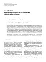
A typical system is shown in Figure 11 ; in addition, bins and conveying equipment are required.
To adsorber
From
adsor.her
F
Figure 11. Reactivation plant. A,
Spent carbon; B, dewatering screw;
C, reactivation furnace; D, quench
tank; E, reactivated carbon tank:
FI,Fz, Fs, eductors.
Operating costs are based on labour, make-up carbon, power, fuel oil (or other heating medium)
and steam if a stripping regeneration process is envisaged.
The heat input, HR, required for regeneration is based on equation (42)
where HI is the thermal capacity of the furnace, H2 of adsorbent and H3 of retained fluid in particles.
Thermal capacities are based on a temperature drop, AT, which is the temperature of regeneration minus the adsorbent particle temperature. Other conventional heat losses from the furnace
and the flue gases will occur and a combustion efficiency for the fuel of 45 % has been reported.49
As shown in Figure 11 adsorbent is fed from the adsorbers to a spent carbon tank and from there
via a dewatering screw-feed system into the furnace. The reactivated adsorbent is quenched with
treated water and transferred to a storage tank where it is held for re-use.
An alternative regeneration system utilising purge gas has been reported,6e in which an efficiency
factor, vefr, for thermal regeneration has been correlated against the function, BHZ/cpgG, where
BH is the overall particle heat transfer coefficient, Z is the packed-bed height, Cpg is the specific
heat of gas and G’ is the superficial gas mass velocity.
Total regenerating time may be calculated from the heating and cooling cycle times and the carbonusage rate must be balanced against these to supply sufficient regenerated adsorbent.
Regeneration with solutions is often used, although the method produces a small additional
effluent. A major development described previously 2o is the implementation of biological regenera-
Design models for adsorption systems in wastewater treatment
729
tion. Certain adsorbents, such as peat and wood, are much cheaper than most of their competitors
and, whereas they could not withstand higher temperature regeneration, the material could be
burned and used as a source of low-grade heat.
4. Costing and optimisation
From the basic design equations, the minimum costs for the system can be obtained by optimising
the size of the adsorption and regeneration units. Bed depth and flow rate determine residence
time; the total costs, direct and indirect, may be plotted against residence time. Figure 12 shows
this effect and indicates a minimum total operating cost for a specific residence time.
u)
t
u)
0
0
.-C
t
e
0)
2
Direct cost
CI
0
Figure 12. Optimisation to determinz
residence time.
Residence time
5. Conclusions
The various methods of solid-liquid contacting in adsorption systems have been considered. In
fluidised bed systems higher mass-transfer rates are obtained and smaller adsorbent particles may
be used thus giving a large external surface area for adsorption. The control of such systems is
more difficult than in a fixed-bed column and there is a lack of flexibility in operation. Fixed-bed
adsorbers are most widely used and the effluent is continuously coming into contact with fresh
adsorbent and therefore the driving force to reach equilibrium is high. In batch processes a relatively
long contact time is needed to reach equilibrium and a further solid-liquid separation stage is
needed at the end of the process.
The economics of adsorption systems depend on the selection of the correct adsorbent, the
method of contacting and the regeneration system. Several methods of designing adsorption systems
for wastewater treatment have been considered. The design of the reactivation unit is presented and
the technique of minimising the cost of adsorption plant has been discussed. The procedures outlined adopt a ‘simplified’ approach to design in the sense that detailed kinetic and mass-transfer
steps have not been incorporated into the models. Nevertheless there is considerable evidence in
the literature that the methods may be used successfully and should be used with some basic design
‘common sense’. It is usually beneficial in wastewater treatment plants to allow some overdesign
to account for certain factors: (i) flow rate surges; (ii) changes in feed concentration; (iii) increased
G.McKay
730
throughput requirements or increased levels of effluent quality; (iv) decreased adsorbent
performance due to numerous reactivations.
References
I.
2.
3.
4.
5.
6.
7.
8.
9.
10.
1I.
12.
13.
14.
IS.
16.
17.
18.
19.
20.
21.
22.
23.
24.
25.
26.
27.
28.
29.
30.
31.
32.
33.
34.
35.
36.
37.
38.
39.
40.
41.
42.
43.
44.
45.
46.
47.
48.
49.
SO.
51.
52.
53.
54.
55.
56.
Rizzo, J. L. Chem. Engng Progr. Symp. Ser. 1971, 67,466.
MacCrum J. M. Proc. Amer. Assoc. Text. Chem. Colorists Symp. Atlanta, 1971, p. 133.
Molvar, A. E.; Rodman. C. A.; Shunney, E. L. Text. Chem. Colourist 1970, 2, 36.
Activated Carbon Reclaims Textile Industry's Waste Waters Enoiron. Sci. Tech. 1969, 3, 314.
Hassler, J. W. Activated Carbon, Chemical Publishing Co., Inc., New York, 1963.
Evaluation of Granular Carbon for Chemical Process Applications D-116, ICI America, Inc., May, 1962.
Euahtatioti of Granular Carbon in Columns for Wasrewater Treatment PC-3, ICI America, Inc., May, 1972.
Davies, R. A , ; Hartmut, J. K.; Clemens, M. M. Chem. Indy 1973, 1, 827.
Fornwalt, H. J.; Helbig, W. A.; Scheffler, G. H. Br. Chem. Engng August, 1963.
Fornwalt, H. J.; Hutchins, R. A. Chem. Engng April, 1966.
Joyce, R. S.;Valentine, A. S. Activated Carbon in Wastewater Treatment Seminar on Advanced Waste Treatment Research, Cincinnati, Ohio, 1962.
Hager D. G.; Fulker, R. D. War. Treat. Exam. 1968, 17,41.
Gauatlett, R. @.;,Packham,R. F. Chem. Indy 1973, 1, 812.
W e e r >W. J.; M,&nis,J. C. J. Am. 'Vht.W k s Ass. 1964, 56, 447.
Piihter, H. A. Chem. In8y 1973, 1, 818.
Bartell, F. E.; Sloan, C. K. J . Am. Chem. SOC.1929, 51, 1643.
Gustafson, L. Ind. Engng Chem. Prod. Res. Dew. 1968, 7, 107.
Oehme, C.; Martinola, F. Chem. Indy 1973, 1, 823.
Robeck, G. G.; Dostal, K. A.; Cohen, J. M.; Kreissl, J. F. J. Am. War. Wks Ass. 1965, 57, 181.
Fram Corporation Bio-Regenerated Activated Carbon Treatment of Textile Dye Wastwater Wat. Poll. Contr.
Res. Ser., Project No. 12090 DWM, 1971.
Mittelstaedt, 0. R. Tappi 1968, 51, 61A.
Pitman, R. W.; Wells, C. W. J. Am. War. W k s Ass. 1968, 60, 1167.
Middleton, A. B. Am. DyestuflReptr. August, 1971, 26.
McKay, G.; Alexander, F. Chem. Engng 1977, 319,244.
McKay, G.; Poots, V. J. P.; Alexander, F. Ind. Engng Chem. Process Res. Dev. 1978, 17, 406.
Mutch, N. Q.J. Pharm. Pharmac. 1946,19,490.
Parsons, C. L. Min. Technol. 3 Bull. 71, US Bureau of Mines, 1913, p. 32.
Thornton, H. A.; Moore, J. R. Sewage Ind. Wastes 1953, 23,497.
Williamson, J. N.; Heit, A. H.; Calrnon, C. Public Health Services Publications, No. 999-WP-14, vol. 12, 1964.
McKay, G.; Otterburn, M. S.;Sweeney, A. G. J.S.D.C. Aug, 1978, 357.
Silvo, E. Proc. 4th Internat. Peat Congr. Otaniemi, Finland, Vol. 4, 1972, 31 1.
Tinh, V. Q.; Le Blanc, R.; Janssens, J. M.; Ruel, M. Canadian Inst. Min. Metall. Bull. 1971, 64,99.
Farnham, R. S.:Brown, J. L. Proc. 4th Infernat. Peat Congr. Otaniemi, Finland, Vol. 4, 1972, 271.
Ottemeyer, W. Gesundh. Ingr. 1930, 53, 185.
Poots, V. J. P.: McKay, G.; Healy, J. J. Water Res. 1976, 10, 1061.
Poots, V. J. P., McKat, G.; Healy, J. J. Scient. Proc. Roy. Dublin Soc., Ser. A 1978, 6, 61.
Leslie, M. Am. Dyesrufls Reptr. 1974, 63, 15.
Poots, V. J. 0.; McKay, G. Proc. R. Irish Acad. 1977, 47, 539.
Poots, V. J. P.; McKay, G.; Healy, J. J. Water Res. 1976, 10, 1067.
Poots, V. J. P.; McKay, G.; Healy, J. 5. J . W.P.C.F. May, 1978, 926.
Collins, J. J. Chem. Engng Prog. Symp. Series No. 74.
Michaels, A. S. Ind. Engng Chem. 1952.44, 1922.
Rosen, J. B. Ind. Engng Chem. 1954, 46, 1590.
Heister, N. K.; Vermeulen, T.; Klein, G. Chemical Engineers Handbook (Perry, R. H., Ed.), McGraw-Hill,
1977.
Lukchis, G. M. Chem. Engng. 1973,80, 1 I I.
Lukchis, G. M. Chem. Engng. 1973,80,83.
Mair, J. B.: Westhaver, J. W.; Rossini, F. D. Ind. Engng Chem. 1950, 42, 1279.
White, G. E. Chem. Engng Prog. 1950, 46, 363.
Johnston, W. A. Chem. Engng 1972,79,87.
Allen, H. V. Petr. ReJ July, 1944.
Strain, H. H. Ind. Engng Chem 1950, 42, 1307.
Johnston, R. L.;Baumann, E. R. J . W.P.C.F. 1971, 43, 1640.
Berg, C. Trans. Am. Ind. Chem. Engng 1946,42,665; Chem. Engr. Prog. 1951,47. 585
Kehde, H.; Faifield, R. G.; Frank, J. C.; Zahnstecker, L. W. Chem. Engng Prog. 1948,44, 575.
Swinton, E. A.; Weiss, D. E.; etal. Austral. J. appl. Sci. 1953, 4, pp. 316,510,519, 530, 543.
Hancher, C. W.; Jury, S. H. Chem. Engng Prog. Symp. Ser. 55 N o . 24, 1959, p. 87.
Deaip models for adsorption systems in wastewater treatment
57.
58.
59*
60.
61.
62.
63.
64.
65.
66.
67.
68.
69.
731
Higgins, 1. R.; Roberts, J. T. Chem. Engng Prog. Symp. Ser. 50 No. 14, 1954, p. 87.
Anon. Chem. Engng April 15, 1963,10, 92.
Errnenc, E. D. Chem. Engng 1961, 68,87.
Weber, W. J.; Morris, J. C. J. War. Poll. Control. Fed. 1965, 31, 425.
Etherington, L. D.; Fritz, R. J.; Nicholson, E. W.; Scheeline, H. W. Chem. Engng Prog. 1956, 52, 274.
Leva. M. Fluidination McGraw-Hill. New York. 1959.
Zenz, F. A. In Modern Chemical Engineering (Acrivos, A., Ed.), Reinhold Publishing Corporation, New York,
1963.
Zenz, F. A.; Othrner, D. F. Fluidisation and Fluid Particle Sysrems Reinhold Publishing Corporation, New
York, 1960.
Davidson, J. F.; Harrison, D. Fluidisation Academic Press, London and New York, 1971.
Kunii, D.; Levenspiel, 0. Fluidisation Engineering J Wiley and Co., New York, 1969.
Rosen, J. B. J. Phys. Chem. 1952, U ,387.
Amundsen, N. R.; Karten, P. R.; Lapidus, L. J. J . Phys. Chem. 1952, 56, 683.
Culp, G . L.; Culp, R. L. New Concepts in Water Purification Van Nostrand Reinhold Environmental Engineering Series, New York.