Design of LCL filters for the back to back converter in a doubly fed induction generator
Bạn đang xem bản rút gọn của tài liệu. Xem và tải ngay bản đầy đủ của tài liệu tại đây (590.8 KB, 6 trang )
IEEE PES ISGT ASIA 2012 1569538915
1
Design of LCL Filters for the Back-to-back
Converter in a Doubly Fed Induction Generator
Peng Zhan, Student Member, IEEE, Weixing Lin, Student Member, IEEE, Jinyu Wen*, Member, IEEE,
Meiqi Yao, Naihu Li, Member, IEEE
well designed [2].
There have been reports on using LCL filters to the GSC
[3-5] and reports on designing LC filter for the RSC [6]. In [3],
an LCL filter for inverter of wind power was introduced, and
the characteristics of the LCL filter compared with the L filter
were investigated. Paper [4] investigated the damping of
resonance oscillations for grid side converter with LCL filter
for doubly-fed wind power system. Paper [5] gave an
optimized design rule of the LCL filter for inverter of a wind
turbine. As to LCL filter for rotor side converter, in [6], a
second-order output LC filter was inserted between the
inverter and the rotor circuit of a DFIG. Taking the rotor
leakage inductance into consideration, it is an LCL filter
essentially. However, no design details were provided. Very
few paper exists on designing LCL filters for both the GSC
and the RSC to date.
This paper designs a Y connected LCL filter for GSC and a
delta connected LCL filter for RSC of a 2.5MW DFIG, and
the design procedures are proposed as well. Simulation and
analysis results validate the effectiveness of the designed
filters in attenuating harmonics.
Abstract--Wind power generator based on Doubly Fed
Induction Generator (DFIG) incorporates a back-to-back PWM
converter. Filters are used to eliminate the harmonics produced
by the PWM converter. However, very few papers have detailed
the design procedure of the filters for a DFIG based wind power
generator. A systematic procedure to design the LCL filters for
DFIG back-to-back converter is proposed in this paper. Both
filters for the grid side converter and the rotor side converter are
designed. Simulations in PSCAD/EMTDC verify the effectiveness
of the design procedure.
Index Terms-- LCL filter, doubly fed induction generator
(DFIG), back-to-back converter
I. INTRODUCTION
Doubly fed induction generators (DFIG) are widely used in
wind power systems. A back-to-back PWM converter in
DFIG, consisting of grid side converter (GSC) and rotor side
converter (RSC), guarantees its good performance. As there
are power electronic devices, harmonics produced by the
converters will be a problem. Harmonics in the rotor currents
cause undesirable fluctuations of generating active and
reactive powers, and harmonics in the stator currents
deteriorate the utility power quality. In order to comply with
corresponding standards [1], it is necessary to equip the
converters with low-pass filters.
Traditionally, an L filter or LC filter is be implemented to
eliminate high-frequency harmonics. However, since the
capacitance of the PWM converter in a DFIG is large, the
switching frequency is not very high. Thus, to attenuate
harmonics in comparatively low frequencies, large inductance
is required, which will result in large size and weight of the
filter. Though an LC filter can get higher harmonics
attenuation than an L filter, it is not suitable for using in grid
connected converter due to its low output impedance. An LCL
filter can provide higher harmonic attenuation than that of the
L filter, which is a better choice in DFIG application.
However, resonance may occur if the LCL filter has not been
II. LCL FILTER PRINCIPLE ANALYSIS
A. Characteristic analysis of LCL filter
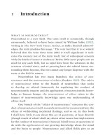
Fig. 1 presents the schematic diagram of an LCL filter
which is inserted between a PWM converter and the grid.
Where, UO is terminal voltage of PWM converter, US is grid
voltage, L1 is the converter side inductor, R1 is the equivalent
resistance of L1, L2 is the grid side inductor, R2 is the
equivalent resistance of L2, C3 is the capacitor, R3 is the
damping resistor in series with C3.
This work was supported in part by the National Natural Science
Foundation of China (50937002) and the National Basic Research Program of
China (2009CB219701, 2012CB215106).
P. Zhan, W. Lin and J. Wen (contact author) are with State Key Laboratory of Advanced Electromagnetic Engineering and Technology (Huazhong
University of Science and Technology), Wuhan 430074, Hubei Province,
China). (E-mails: , ,
).
M. Yao and N. Li are with the Alstom Grid China Technology Center,
Shanghai, China. (E-mails: , ).
Fig. 1. LCL filter equivalent circuit diagram
Ignoring R1 and R2, the LCL filter can be viewed as L2 and
C3 paralleled, then, together they are in series with L1. The
transfer function between the input voltage UO and the output
1
2
current I2 is:
H (s) =
R3C3 s + 1
3
2
L1 L2 C3 s + ( L1 + L2 ) R3 C3 s + ( L1 + L2 ) s
C3 ≤ 5% ×
(6)
2
3 × 2π f BU rated
Where Prated is the rated power of the converter, fB is the
grid frequency, Urated is the RMS value of converter output
phase voltage.
2) Select the desired current ripple reduction σ with
respect to the ripple on the converter side to design the
inductance of L2. Thus in total the L2C2 part reduces the grid
current ripple to a very low level.
(1)
While for an L filter, the transfer function becomes:
1
H (s) =
(2)
sL
Equation (1) is of third order. It is expected that the LCL
filter gets higher harmonics attenuation at high frequency than
the L filter with a first order transfer function.
The filter parameters L1, L2, C3, and R3 greatly influence
the performance of the LCL filter. Poorly designed parameters
will not reach the expected attenuation effect or even cause
distortion increase due to oscillation effects [2]. The following
section will describe how to design these parameters
following a step-by-step procedure.
σ=
U dc
8 f PWM L1
U dc
ωres =
ωres =
U dc / 3 − U m
2
(3)
2
=10%
(7)
L1 + L2
L1 L2 C3
(9)
L1 + L2
3 L1 L2 C3
(10)
Transfer function in (8) has a pair of poles located at the
imaginary axis. The imaginary poles will cause oscillation to
the system, which requires the filter to be damped to avoid
resonance problems.
Damping resistors are widely used to increase the stability
of the system due to its simplicity and reliability. Studies have
shown that the greater the damping resistor, the better
resonant inhibition [3, 8]. However, larger damping resistor
will cause larger power losses. Generally, R3 is set at one-third
the impedance of capacitor at resonant frequency [2],
1
(12)
R3 =
3ωres C3
2
ωB I m
L2 C3ωPWM − 1
After designing L1, L2, and C3, the resonant frequency
should be verified. If the limit is not satisfied, the parameters
would be changed accordingly.
4) Without damping resistor R3, equation (1) becomes
1
(11)
H (s) =
3
L1 L2 C3 s + ( L1 + L2 ) s
However, in order to improve the ability of current tracking
and avoid large ac voltage drop, L1 cannot be too large [7]. L1
is also limited by
L1 ≤
1
For a delta connected LCL filter, ωres is
(4)
8irip f PWM
iC ( f PWM )
=
For a Y connected LCL filter, the resonant frequency ωres is
expressed as
Where Udc is the converter dc-link voltage, fPWM is the
switching frequency. Thus to reach a desired current ripple irip,
L1 is designed following:
L1 ≥
ig ( f PWM )
Where ig(fPWM) and iC(fPWM) are grid current ripple and
converter current ripple at the switching frequency.
3) To avoid resonance problems in the lower and upper
parts of the harmonic spectrum, ωres should be in a range
between ten times the grid frequency and one-half of the
switching frequency, i.e.,
(8)
10ωB < ωres < 1 / 2ωPWM
B. Constraints on LCL filter design
With the free variables in equation (1), the solution of the
LCL filter parameters is not exclusive, which brings difficulty
in the filter design. However, according to the desired ripple
attenuation ratio and other requirements [2], constraints on the
values of L1, L2, C3, and R3 can be deduced.
1) The total value of inductance should limit current
ripple of I1 to 15%-25% of rated current [3]. In Fig. 1, the
current I1 depends on the impedance of L1 (denoted as XL1)
and the parallel impedance of L2 and C3 (denoted as XL2C3).
The impedance of C3 (denoted as XC3) at switching frequency,
should be much smaller than the impedance of L2 at switching
frequency (denoted as XL2) to ensure that most of the high
frequency currents flow through C3 branch, so the parallel
impedance is dominated by XC3. Because XC3 is small, I1 is
mainly determined by XL1, which requires large L1 value to
limit current ripple. The maximum current ripple in a PWM
switching period is estimated as
irip max =
Prated
(5)
Where Um is the peak phase voltage of gird, Im is the peak
current of grid, ωB is the angular frequency of grid voltage.
Low impedance of XC3 means large capacitor value of C3,
which will result in large reactive power. For converters
directly connected to the grid, the reactive power by C3 is
generally less than 5% of rated power with the power factor
limit. Thus, C3 is designed following:
III. LCL FILTERS DESIGN FOR BACK-TO-BACK
CONVERTER OF DFIG
2
3
L2g=0.73mH is calculated using (7). Thus in total the L2gC3g
part reduces the grid current ripple to 2%.
The consequent resonant frequency is 775Hz, which is in
the range between 10fB (500Hz) and 1/2fPWM (975Hz).
4) The impedance of the filter capacitor at the resonant
frequency is 2.05Ω, so the damping value R3g is chosen as
one-third, i.e., 0.68Ω.
A. System configuration
TABLE I
LCL filter parameters on GSC side
L1g
1.0e-3H
Fig. 2. Configuration of a DFIG system with two LCL filters
L2g
0.73e-3H
Rg
0.68Ω
Cg
100μF
In summary, the LCL filter parameters on GSC side are list
in TABLE I.
Fig. 2 shows the overall configuration of a DFIG system
with a Y connected LCL filter on GSC side and a delta
connected LCL filter on RSC side respectively. The DFIG is
rated at 2.5MW with a 690V voltage (line to line, 50Hz). The
stator rotor turns ratio is 0.3, and other parameters are listed in
the Appendix. The converter dc-link capacitor is 20,000uF,
the dc-link reference voltage is set at 1,200V, and the
switching frequency is 1,950Hz for both the converters.
With the control of the back-to-back converter, DFIG
realizes maximum wind power tracking control and decoupled
P-Q control [9]. The controllers are typically designed in a dq
rotating frame using proportional-plus-integral (PI) based
control strategies. The appearance of the LCL filter brings a
little change to the rotating frame as well as the controller
design. In [10], state feedback control was used to guarantee
the stability of a PWM inverter with an LCL filter. However,
the approach increased complexity in the control algorithm.
In fact, PI control parameters are generally designed only
considering the low frequency components. As the
fundamental component of the output currents of both GSC
and RSC is at low frequency, and the capacitor branch
presents low pass characteristics for the high frequency
components, the capacitor branch can be neglected while
determining the control parameters. Thus the PI controllers for
the converter with LCL filters can be designed by only
adapting the parameters of the PI controllers that is already
used for the converter with L filter configuration.
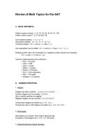
Substituting L1g, L2g, C3g and R3g into (1), the transfer
function becomes:
H (s) =
6.8 × 10⁻⁵ s + 1
7.3 × 10
−11 3
−7 2
−3
s + 1.18 × 10 s + 1.73 × 10 s
(13)
Bode Diagram
50
0
Frequency (Hz): 1950
Magnitude (dB): -37.2
-50
-100
-90
-135
-180
-225
1
10
3
10
2
10
4
10
Frequency (Hz)
Fig. 3. Bode plot of LCL filter on GSC side
The bold lines in Fig. 3 are the bode plot of the LCL filter
on GSC side. It can be seen that the filter has satisfactory
filtering performance with the gain of -37.2dB for 1950Hz
signal, and higher frequency harmonics get higher attenuation.
The slender lines shows the bode plot of an L filter with a
7.2mH inductance. It can be concluded that in order to get the
same attenuation as the LCL filter, a much larger inductance
value is required for the L filter.
B. Y connected LCL filter design for GSC
Taking the constraints proposed in Section II into
consideration, the systematic procedure to design the filter on
GSC side is as follows.
1) According to (4), in order to obtain a 20% current
ripple of I1g, a minimum value of 0.65mH is required for
inductance L1g. L1g should be less than 2.2mH according to (5).
Here, 1.0mH is adopted for L1g.
2) The maximum value of capacitor C3g is 167μF under
the 5% power factor limit, but capacitor value cannot be too
low to avoid too high a value of grid side inductance L2g. Here
C3g is set at 100μF. If other constraints cannot be met, it will
be increased up to the maximum value.
3) Selecting a current ripple attenuation of 10% with
respect to the ripple on the converter side, a value of
C. Delta connected LCL filter design for RSC
The frequency of RSC current varies in accordance with the
rotor speed to keep stator frequency constant. Assume the
DFIG in our study operates at a maximum speed of 1.2pu on
high wind speed conditions. Thus a 0.2pu slip frequency
exists and consequently the rotor current frequency is 10Hz
(in negative sequence).
3
4
Rr
I2r
Lrσ
E r
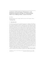
As can be seem from Fig. 5, a gain of -47.8dB is obtained
for 1,950Hz harmonic, which shows the good performance of
the filter on attenuating high frequency harmonics. It can be
found that this system is unstable because the resonant peak is
above 0dB. In order to enhance the system stability, Rr3 is
increased. The slender lines are the bode plot with Rr3 equals
1.14Ω (2 times of 0.57Ω). With the larger damping resistor,
the resonant peak is below 0dB, so the designed value of Rr3 is
changed to 1.14Ω. It can be seen that the greater the passive
damping resistor, the better resonant inhibition, but larger
losses will be caused.
L1r I2c
L2r
U Cr
C3r
Fig. 4. Equivalent circuit of DFIG rotor side with the LCL filter
Phase (deg)
Magnitude (dB)
Fig. 4 shows the equivalent circuit of DFIG rotor side with
the LCL filter. Lrσ and Rr is the rotor leakage inductance and
the rotor resistor respectively. Er is the induced electromotive
force. Neglecting Rr, some differences exist in designing the
LCL filter on RSC side due to the existing Lrσ. The detailed
designing procedures are:
1) In order to obtain a 20% current ripple of I1r, a
minimum value of 0.36mH is required for inductance L1r
according to (4). To enhance the ability of current tracking, L1r
is set at 0.5mH, a little larger than the required value, which is
also less than 4.6mH according to (5).
2) The filter is delta connected on RSC side. With less
capacitance, the delta connected LCL filter can achieve the
same harmonics attenuation as Y connected LCL filter [11].
The maximum value of capacitor is 633μF under the 5%
power factor limit. Here C3r is set at 300μF. In order reach a
current ripple attenuation of 10% with respect to the ripple on
the converter side, a value of L2r=0.05mH is calculated using
(7). However, the existing rotor leakage inductance Lrσ is
0.106pu, which is 0.71mH when converted to rotor side.
Because Lrσ is much larger than the required value, it will play
the role of L2r. Thus L2r can be omitted. Thus with the LrσC3r
part, a current ripple attenuation of more than 10% with
respect to the ripple on the converter side can be reached. It
must be pointed out that if Lrσ is smaller than the required
value, an extra inductance should be added to rotor side.
3) The consequent resonant frequency is 310Hz, which is
also in the range between 10fB (100Hz) and 1/2fPWM (975Hz).
4) The damping value R3g is set at 0.57Ω in delta
connection, one-third of the impedance of the capacitor at the
resonant frequency, 1.71Ω.
The parameters are list in TABLE II.
Fig. 5. Bode plot of LCL filter on RSC side
IV. SIMULATION AND ANALYSIS
The DFIG with the two LCL filters proposed is modeled
and simulated in PSCAD/EMTDC. The phase A currents on
GSC side are shown in Fig. 6(a) and Fig. 6 (b), where ICA is
the converter output current and IgA is the current into the grid.
The currents are analyzed using FFT, and their spectrums
are shown in Fig. 6(c) and Fig. 6 (d). It can be found that the
lowest frequency current ripple of the currents is around
1,950Hz, 3,900Hz and 5,850Hz ect. It’s obvious that
harmonics magnitude of ICA is much higher than IgA.
The Total Harmonics Distortion (THD) is used to evaluate
the filtering performance. THD is expressed as
TABLE II
LCL filter parameters on RSC side
L1r
5.0e-4H
L2r
—
R3r
0.57Ω
∞
I 2 (h)
C3r
300μF
THD=
h=2
(15)
I (1)
Where I(1) is the RMS value of fundamental current and
Transforming the value C3r and R3r in delta connection into I(h) is the RMS value of the hth harmonic current. RMS values
the Y connection, and then substituting the parameters into (1), and the THDs of the currents are list in TABLE III.
the transfer function becomes:
TABLE III
Phase A current of GSC (RMS: kA)
−4
H (s) =
1.7 × 10 s + 1
3.2 × 10
−10 3
−7 2
−3
s + 2.1 × 10 s + 1.2 × 10 s
(14)
Overall
current(kA)
According to (14), the bode plot of the designed LCL filter
on RSC side is shown with the bold lines in Fig. 5.
4
Fundamental
current(kA)
Overall-harmonic
currents(kA)
THD
ICA
0.2401
0.2387
0.0264
11.05%
IgA
0.2397
0.2396
0.0041
1.70%
5
(d)
Mag(kA)
(d)
Mag(kA)
(c)
Mag(kA)
(c)
Mag(kA)
(b)
IgA/kA
(b)
IrA/kA
(a)
ICA/kA
(a)
IcA/kA
It can be seen that current THD is significantly reduced
from 11.05% on converter side to 1.70% on grid side, which
shows the effectiveness of the LCL filter.
Fig. 7. Phase A currents on RSC side and the spectrum
V. CONCLUSION
By analyzing the characteristic of the LCL filter, the
constraints on designing the parameters of the LCL filter are
provided. Based on the constraints, two LCL filters, one in Y
connection and one in delta connection, are designed for the
back-to-back converter of a 2.5MW DFIG. The detailed
design procedures are proposed as well. PSCAD/EMTDC
simulation and analysis results show that the THD of the
current after filtering is 1.70% on GSC side and 1.64% on
RSC side respectively, which verified the effectiveness of the
designed filters in attenuating harmonics produced by the
back-to-back converter.
Fig. 6. Phase A currents on GSC side and the spectrums
Taking into account the active power consumed by the
damping resistor and the reactive power provided by the
capacitor, the losses are 0.48% of rated power, and the power
factor is 4.4% consequently.
Phase A currents on RSC side with their spectrums are
shown in Fig. 7. IcA is the converter side current and IrA is
rotor side current. The analysis results are list in TABLE IV.
TABLE IV
Phase A currents on RSC side (RMS: kA)
VI. APPENDIX
Overall
current
Fundamental
current
Overall-harmonic
currents
THD
IcA
0.5388
0.5374
0.0386
7.19%
IrA
0.5443
0.5442
0.0089
1.64%
DFIG parameters:
Turn ratio:
Stator resistance:
Rotor resistance:
Stator leakage inductance:
Rotor leakage inductance:
Magnetizing inductance:
The fundamental current on rotor side is a little larger than
that of the converter side because the power flows form rotor
side to converter side due to supersynchronous operation. The
THD is 7.19% at converter terminal and it is reduced to 1.64%
on rotor side, and the loss is 0.22%, which also demonstrates
the good performance of the LCL filter.
0.3
0.023pu
0.0396pu
0.104pu
0.106pu
2.93pu
REFERENCES
[1]
5
"IEEE Recommended Practices and Requirements for Harmonic Control
in Electrical Power Systems," IEEE Std 519-1992, p. 0_1, 1993-01-01
1993.
6
[2]
M. Liserre, F. Blaabjerg and S. Hansen, "Design and control of an LCLfilter-based three-phase active rectifier," Industry Applications, IEEE
Transactions on, vol. 41, pp. 1281- 1291, 2005-01-01 2005.
[3] W. Xing, X. Lan, Y. Zhilei, and G. Chunying, "Design of LCL filter for
wind power inverter," in World Non-Grid-Connected Wind Power and
Energy Conference (WNWEC), 2010, 2010, pp. 1-6.
[4] Z. Xianping, "Damping Strategy of Grid-side Converter With New
Topology Filter in Doubly-fed Wind Power System,". vol. 29, L. Yaxi,
Ed., 2009, pp. 1-7.
[5] Q. Zhiling and C. Guozhu, "Study and Design of Grid Connected
Inverter for 2 MW Wind Turbine," in Industry Applications Conference,
2007. 42nd IAS Annual Meeting. Conference Record of the 2007 IEEE,
2007, pp. 165-170.
[6] M. Hacil, A. L. Nemmour, A. Khezzar, and M. Boucherma,
"Improvement generating powers quality of a doubly-fed induction
generator with a second-order LC filter in the rotor circuit," in 18th
International Conference on, 2008, pp. 1-6.
[7] P. A. Dahono, "A control method to damp oscillation in the input LC
filter," in Power Electronics Specialists Conference, 2002. pesc 02. 2002
IEEE 33rd Annual, 2002, pp. 1630- 1635.
[8] V. Blasko and V. Kaura, "A novel control to actively damp resonance in
input LC filter of a three-phase voltage source converter," Industry
Applications, IEEE Transactions on, vol. 33, pp. 542-550, 1997-01-01
1997.
[9] R. Pena, J. C. Clare and G. M. Asher, "Doubly fed induction generator
using back-to-back PWM converters and its application to variablespeed wind-energy generation," Electric Power Applications, IEE
Proceedings -, vol. 143, pp. 231-241, 1996-01-01 1996.
[10] I. J. Gabe, J. R. Massing, V. F. Montagner, and H. Pinheiro, "Stability
analysis of grid-connected voltage source inverters with LCL-filters
using partial state feedback," in Power Electronics and Applications,
2007 European Conference on, 2007, pp. 1-10
[11] L. Sangin, L. Kui-jun and H. Dong-seok, "Modeling and control of a
grid connected VSI using a delta connected LCL filter," in Industrial
Electronics, 2008. IECON 2008. 34th Annual Conference of IEEE, 2008,
pp. 833-838.
BIOGRAPHIES
Peng Zhan was born in 1987. He received the B.Eng in electrical
engineering from Huazhong University of Science and Technology (HUST),
Wuhan, China in 2010. Currently he is pursuing a Mater degree at HUST. His
research interest is the wind power generation and the control schemes for
integrating wind power to the grid through HVDC.
Weixing Lin was born in 1986. He received the B.Eng in electrical
engineering from Huazhong University of Science and Technology (HUST),
Wuhan, China in 2008. Currently he is pursuing a Ph.D. degree at HUST. His
research interest is control, technical and economic comparisons of different
schemes for integrating wind power to the grid.
Jinyu Wen received the B.Eng. and Ph.D. degrees all in electrical
engineering from HUST, Wuhan, China, in 1992 and 1998, respectively. He
was a visiting student from 1996 to 1997 and research scholar from 2002 to
2003 all at the University of Liverpool UK. In 2003 he entered the HUST and
now is a professor at HUST. His current research interests include smart grid,
renewable energy, energy storage, FACTS, HVDC and power system
operation and control.
6