[]_Hydrocarbon_Processing_Refining_Processes_2000(BookZZ.org)
Bạn đang xem bản rút gọn của tài liệu. Xem và tải ngay bản đầy đủ của tài liệu tại đây (4.47 MB, 95 trang )
Hydrocarbon Processing ®
www.HydrocarbonProcessing.com
Refining Processes 2000
process index
Select a Process
to view
GULF PUBLISHING COMPANY
3 Greenway Plaza, 9th Floor, Houston, TX 77046
Phone 713-529-4301, Fax 713-520-4433
E-mail:
contributor index
Alkylation
Alkylation feed preparation
Aromatics extraction
Aromatics extracted distillation
Aromatics recovery
Benzene reduction
Benzene saturation
Catalytic cracking
Catalytic dewaxing
Catalytic reforming
Coking
Crude distillation
Deasphalting
Deep catalytic cracking
Deep thermal conversion
Delayed coking
Desulfurization
Dewaxing
Electric desalting
Ethers
Fluid catalytic cracking
Gas oil hydrotreatment
Gas treating—H2S removal
key word
process
category/type
next
Hydrocarbon Processing ®
www.HydrocarbonProcessing.com
Refining Processes 2000
process index
Select a Process
to view
GULF PUBLISHING COMPANY
3 Greenway Plaza, 9th Floor, Houston, TX 77046
Phone 713-529-4301, Fax 713-520-4433
E-mail:
contributor index
Gasification
Gasoline desulfurization
Gasoline desulfurization, ultra-deep
Hydrocracking
Hydrocracking, residue
Hydrocracking/hydrotreating—VGO
Hydrodearomatization
Hydrodesulfurization
Hydrodesulfurization—UDHDS
Hydrogenation
Hydrotreating
Hydrotreating—catalytic dewaxing
Hydrotreating—HDAr
Hydrotreating—HDHDC
Hydrotreating, residue
Iso-octane
Isomerization
Lube hydroprocessing
Lube treating
NOx abatement
Oily waste treatment
Olefins recovery
Resid catalytic cracking
Residue hydroprocessing
key word
process
category/type
back
next
Hydrocarbon Processing ®
www.HydrocarbonProcessing.com
Refining Processes 2000
process index
Select a Process
to view
Thermal gas oil process
Treating
Visbreaking
contributor index
key word
process
category/type
back
GULF PUBLISHING COMPANY
3 Greenway Plaza, 9th Floor, Houston, TX 77046
Phone 713-529-4301, Fax 713-520-4433
E-mail:
Hydrocarbon Processing ®
www.HydrocarbonProcessing.com
Refining Processes 2000
process index
contributor index
ABB Lummus Global Inc.
Select a Process
to view
Coking
Fluid catalytic cracking
Hydrocracking
Hydrocracking
Hydrotreating
Isomerization
Thermal gasoil process
Visbreaking
key word
contributing
company/licensor
Akzo Nobel Chemicals B.V.
Hydrodesulfurization—UDHDS
Hydrotreating—catalytic dewaxing
Isomerization
BARCO
Catalytic cracking
Bechtel Corp.
Delayed coking
Dewaxing
Lube treating
BP Corp.
Hydrocracking
CDTECH
GULF PUBLISHING COMPANY
3 Greenway Plaza, 9th Floor, Houston, TX 77046
Phone 713-529-4301, Fax 713-520-4433
E-mail:
Ethers
Hydrogenation
Hydrotreating
Iso-octane/iso-octene
Isomerization
next
Hydrocarbon Processing ®
www.HydrocarbonProcessing.com
Refining Processes 2000
process index
contributor index
Chevron Research and Technology Co.
Select a Process
to view
Hydrocracking
Hydrotreating
Conoco Inc.
key word
contributing
company/licensor
Desulfurization
ELF
back
Crude distillation
ExxonMobil Research & Engineering Co.
Alkylation
Catalytic dewaxing
Gas treating—H2S removal
Hydrotreating—catalytic dewaxing
Lube treating
NOx abatement
Oily waste treatment
Foster Wheeler USA Corp.
Coking
Crude distillation
Deasphalting
Visbreaking
Fuels Technology Division of Phillips Petroleum Co.
GULF PUBLISHING COMPANY
3 Greenway Plaza, 9th Floor, Houston, TX 77046
Phone 713-529-4301, Fax 713-520-4433
E-mail:
Alkylation
Gasoline desulfurization
Isomerization
GTC Technology Corp.
Aromatics recovery
Desulfurization
next
Hydrocarbon Processing ®
www.HydrocarbonProcessing.com
Refining Processes 2000
process index
contributor index
Haldor Topsøe A/S
Select a Process
to view
Hydrodearomatization
Hydrotreating
Howe-Baker Engineers, Inc.
Catalytic reforming
Electrical desalting
Hydrotreating
key word
contributing
company/licensor
back
IFP
Benzene reduction
Catalytic reforming
Fluid catalytic cracking
Gas oil hydrotreatment
Gasoline desulfurization, ultra-deep
Hydrocracking
Hydrocracking/hydrotreating—VGO
Hydrotreating, residue
Isomerization
Resid catalytic cracking
IFP North America
Gasoline desulfurization, ultra-deep
Hydrocracking/hydrotreating—VGO
Imperial Petroleum Recovery Corp.
Oily waste treatment
GULF PUBLISHING COMPANY
3 Greenway Plaza, 9th Floor, Houston, TX 77046
Phone 713-529-4301, Fax 713-520-4433
E-mail:
Kellogg Brown & Root, Inc.
Deasphalting
Fluid catalytic cracking
Hydrocracking
next
Hydrocarbon Processing ®
www.HydrocarbonProcessing.com
Refining Processes 2000
process index
contributor index
Kellogg Brown & Root, Inc. continued
Select a Process
to view
Hydrodesulfurization—UDHDS
Hydrotreating—HDHDC
Iso-octane
Isomerization
Krupp Uhde
key word
contributing
company/licensor
back
Aromatics extractive distillation
Lyondell Chemical Co.
Isomerization
Merichem Co.
Treating
Neste Engineering Oy
Iso-octane
Oxy Research & Development Co.
Hydrocracking
Pro-Quip Corp.
Olefins recovery
Research Institute of Petroleum
Deep catalytic cracking
Shell Global Solutions International B.V.
GULF PUBLISHING COMPANY
3 Greenway Plaza, 9th Floor, Houston, TX 77046
Phone 713-529-4301, Fax 713-520-4433
E-mail:
Crude distillation
Deep thermal conversion
Fluid catalytic cracking
Gasification
Hydrocracking
Hydrotreating
next
Hydrocarbon Processing ®
www.HydrocarbonProcessing.com
Refining Processes 2000
process index
contributor index
Shell Global Solutions International B.V. continued
Select a Process
to view
Lube hydroprocessing
Residue hydroprocessing
Visbreaking
key word
contributing
company/licensor
Shell International Oil Products B.V.
Thermal gasoil process
SK Corp.
back
Lube treating
Snamprogetti SpA
Ethers
Iso-octane/iso-octene
Stone & Webster Inc., a Shaw Group Co.
Deep catalytic cracking
Fluid catalytic cracking
Resid catalytic cracking
Stratco Inc.
Alkylation
TECHNIP
Crude distillation
UOP LLC
GULF PUBLISHING COMPANY
3 Greenway Plaza, 9th Floor, Houston, TX 77046
Phone 713-529-4301, Fax 713-520-4433
E-mail:
Alkylation
Alkylation
Catalytic cracking
Catalytic reforming
Coking
Deasphalting
Fluid catalytic cracking
next
Hydrocarbon Processing ®
www.HydrocarbonProcessing.com
Refining Processes 2000
process index
contributor index
UOP LLC continued
Select a Process
to view
Hydrocracking
Hydrodesulfurization
Hydrotreating
Hydrotreating
Isomerization
Visbreaking
VEBA OEL Technologie und Automatisierung GmbH
Hydrocracking
Washington Group International
Lube treating
GULF PUBLISHING COMPANY
3 Greenway Plaza, 9th Floor, Houston, TX 77046
Phone 713-529-4301, Fax 713-520-4433
E-mail:
key word
contributing
company/licensor
back
REFINING PROCESSES 2000
Propane product
3
2
Refrigerant
1
Recycle
isobutane
4
5
Olefin
feed
START
Recycle acid
Butane
product
Makeup
isobutane
6
Alkylate
product
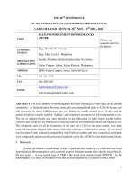
Alkylation
Application: Combines propylene, butylene and pentylene with
isobutane, in the presence of sulfuric acid catalyst, to form a highoctane, mogas component.
Products: A highly isoparaffinic, low Rvp, high-octane gasoline
blendstock is produced from the alkylation process.
Description: Olefin feed and recycled isobutane are introduced into
the stirred, autorefrigerated reactor (1). Mixers provide intimate contact between the reactants and the acid catalyst. Reaction heat is
removed from the reactor by the highly efficient autorefrigeration
method. The hydrocarbons that are vaporized from the reactor, and that
provide cooling to the 40°F level, are routed to the refrigeration compressor (2) where they are compressed, condensed and returned to the
reactor. A depropanizer (3), which is fed by a slipstream from the refrigeration section, is designed to remove any propane introduced to the
back to main menu
plant with the feeds. The reactor product is sent to the settler (4), where
the hydrocarbons are separated from the acid that is recycled. The
hydrocarbons are then sent to the deisobutanizer (5) along with
makeup isobutane. The isobutane-rich overhead is recycled to the
reactor. The bottoms are then sent to a debutanizer (6) to produce a
low Rvp alkylate product with an FBP less than 400°F.
Major features of the reactor are:
• Use of the autorefrigeration method of cooling is thermodynamically
efficient. It also allows lower temperatures, which are favorable for producing high product quality with low power requirements.
• Use of a staged reactor system results in a high average isobutane concentration, which favors high product quality.
• Use of low space velocity in the reactor design results in high product quality and eliminates any corrosion problems in the fractionation section associated with the formation of esters.
• Use of low reactor operating pressure means high reliability for
the mechanical seals for the mixers.
• Use of simple reactor internals translates to low cost.
Yields:
Alkylate yield
Isobutane (pure) required
Alkylate quality
1.78 bbl C5+/bbl butylene feed
1.17 bbl/bbl butylene feed
96 RON/94 MON
Economics:
Utilities, typical per barrel of alkylate produced:
Water, cooling (20°F rise), 1,000 gal
2.1
Power, kWh
10.5
Steam, 60 psig, lb
200
H2SO4, lb
19
NaOH, 100%, lb
0.1
Installation: 100,000-bpd capacity at nine locations with the sizes
ranging from 2,000 to 30,000 bpd. Single reactor/settle trains with
capacities up to 89,000 bpd.
Reference: Lerner, H., “Exxon sulfuric acid alkylation technology,” Handbook of Petroleum Refining Processes, 2nd Ed., R. A. Meyers, ed., pp. 1.3–1.14.
Licensor: ExxonMobil Research & Engineering Co.
Copyright © 2001 by Gulf Publishing Company. All rights reserved.
REFINING PROCESSES 2000
Isobutane recycle
3
Propane
Olefin feed
1
START
2
Motor fuel butane
Isobutane
START
Alkylate
required)
• Low catalyst consumption
• Low operating cost
• Superior alkylate qualities from propylene, isobutylene and
amylene feedstocks
• Onsite catalyst regeneration
• Environmentally responsible (very low emissions/waste)
• Between 60%–90% reduction in airborne catalyst release over
traditional catalysts
• Can be installed in all licensors’ HF alkylation units.
With the proposed reduction of MTBE in gasoline, ReVAP offers
significant advantages over sending the isobutylene to a sulfuricacid-alkylation unit or a dimerization plant. ReVAP alkylation produces higher octane, lower RVP and endpoint product than a sulfuric-acid-alkylation unit and nearly twice as many octane barrels as
can be produced from a dimerization unit.
Feed type
Butylene
Propylene-butylene mix
Yields:
Alkylation
Application: Convert propylene, amylenes, butylenes and isobutane
to the highest quality motor fuel using ReVAP alkylation.
Products: An ultra-low-sulfur, high-octane and low-RVP blending
stock for motor and aviation fuels.
Description: Dry liquid feed containing olefins and isobutane is
charged to a combined reactor-settler (1). The reactor uses the principle of differential gravity head to effect catalyst circulation through
a cooler prior to contacting highly dispersed hydrocarbon in the
reactor pipe. The hydrocarbon phase that is produced in the settler
is fed to the main fractionator (2), which separates LPG-quality
propane, isobutane recycle, n-butane and alkylate products. Small
amount of dissolved catalyst is removed from the propane product
by a small stripper tower (3). Major process features are:
• Gravity catalyst circulation (no catalyst circulation pumps
back to main menu
Composition (lv%)
Propylene
Propane
Butylene
i-Butane
n-Butane
i-Pentane
Alkylate product
Gravity, API
RVP, psi
ASTM 10%, °F
ASTM 90%, °F
RONC
Per bbl olefin converted
i-Butane consumed, bbl
Alkylate produced, bbl
0.8
1.5
47.0
33.8
14.7
2.2
24.6
12.5
30.3
21.8
9.5
1.3
70.1
6–7
185
236
96.0
71.1
6–7
170
253
93.5
1.139
1.780
1.175
1.755
Installation: 107 alkylation units licensed worldwide.
Licensor: Fuels Technology Division of Phillips Petroleum Co.
Copyright © 2001 by Gulf Publishing Company. All rights reserved.
REFINING PROCESSES 2000
Propane
product
5
6
2
n-Butane
product
3
1
Olefin feed
4
Alkylate
product
START
i-Butane
START
Alkylation
Application: To combine propylene, butylenes and amylenes with
isobutane in the presence of strong sulfuric acid to produce highoctane branched chain hydrocarbons using the Effluent Refrigeration Alkylation process.
Products: Branched chain hydrocarbons for use in high-octane
motor fuel and aviation gasoline.
Description: Plants are designed to process a mixture of propylene,
butylenes and amylenes. Olefins and isobutane-rich streams along
with a recycle stream of H2SO 4 are charged to the Contactor (1). The
liquid contents of the Contactor are circulated at high velocities
back to main menu
and an extremely large amount of interfacial area is exposed between
the reacting hydrocarbons and the acid catalyst from the acid settler
(2). The entire volume of the liquid in the Contactor is maintained
at a uniform temperature, less than 1°F between any two points
within the reaction mass. Reactor products pass through a flash drum
(3) and deisobutanizer (4). The refrigeration section consists of a compressor (5) and depropanizer (6).
The overhead from the deisobutanizer (4) and effluent refrigerant
recycle (6) constitutes the total isobutane recycle to the reaction
zone. This total quantity of isobutane and all other hydrocarbons is
maintained in the liquid phase throughout the Contactor, thereby
serving to promote the alkylation reaction. Onsite acid regeneration
technology is also available.
Product quality: The total debutanized alkylate has RON of 92 to
96 clear and MON of 90 to 94 clear. When processing straight
butylenes, the debutanized total alkylate has RON as high as 98 clear.
Endpoint of the total alkylate from straight butylene feeds is less than
390°F and less than 420°F for mixed feeds containing amylenes in
most cases.
Economics (basis: butylene feed):
Investment (basis: 10,000-bpsd unit), $ per bpsd
Utilities, typical per bbl alkylate:
Electricity, kWh
Steam, 150 psig, lb
Water, cooling (20oF rise), 103 gal
Acid, lb
Caustic, lb
3,500
13.5
180
1.85
15
0.1
Installation: Nearly 600,000 bpsd installed capacity.
Reference: Hydrocarbon Processing, Vol. 64, No. 9, September
1985, pp. 67–71.
Licensor: Stratco, Inc.
Copyright © 2001 by Gulf Publishing Company. All rights reserved.
REFINING PROCESSES 2000
Light ends
LPG
i-C4/H2
3
2
Olefin feed
4
Alkylate
i-C4/H2
1
Isobutane recycle
Alkylation
Application: The Alkylene process uses a solid catalyst to react isobutane with light olefins (C3 to C5) to produce a branched-chain paraffinic fuel. The performance characteristics of this catalyst and novel
process design have yielded a technology that is competitive with traditional liquid-acid-alkylation processes. Unlike liquid-acid-catalyzed technologies, significant opportunities to continually advance
the catalytic activity and selectivity of this exciting new technology
are possible. This process meets today’s demand for both improved
gasoline formulations and a more “environmentally friendly” light
olefin upgrading technology.
back to main menu
Description: Olefin charge is first treated to remove impurities such
as diolefins and oxygenates (1). The olefin feed and isobutane recycle are mixed with reactivated catalyst at the bottom of the reactor
vessel riser (2). The reactants and catalyst flow up the riser in a cocurrent manner where the alkylation reaction occurs. Upon exiting the
riser, the catalyst separates easily from the hydrocarbon effluent liquid by gravity and flows downward into the cold reactivation zone
of the reactor. The hydrocarbon effluent flows to the fractionation section (3), where the alkylate product is separated from the LPG product. There is no acid soluble oil (ASO) or heavy polymer to dispose
of as with liquid acid technology.
The catalyst flows slowly down the annulus section of the reactor
around the riser as a packed bed. Isobutane saturated with hydrogen
is injected to reactivate the catalyst. The reactivated catalyst then
flows through standpipes back into the bottom of the riser. The reactivation in this section is nearly complete, but some strongly adsorbed
material remains on the catalyst surface. This is removed by processing a small portion of the circulating catalyst in the reactivation vessel (4), where the temperature is elevated for complete reactivation. The
reactivated catalyst then flows back to the bottom of the riser.
Product quality: Alkylate has ideal gasoline properties such as: high
research and motor octane numbers, low Reid vapor pressure (Rvp),
and no aromatics, olefins or sulfur. The alkylate from an Alkylene
unit has the particular advantage of lower 50% and 90% distillation
temperatures, which is important for new reformulated gasoline
specifications.
Economics: (basis: FCC source C4 olefin feed)
Investment (basis: 6,000-bpsd unit), $ per bpsd
Operating cost ($/gal)
4,940
0.54
Licensor: UOP LLC.
Copyright © 2001 by Gulf Publishing Company. All rights reserved.
REFINING PROCESSES 2000
Makeup H2
Olefin
feed
Offgas
5
1
2
4
3
LPG
Alkylate
Alkylation
Application: The UOP Indirect Alkylation (InAlk) process uses
solid catalysts to react isobutylene with light olefins (C3 to C5 ) to produce a high-octane, low-vapor pressure, paraffinic gasoline component similar in quality to traditional motor alkylate.
Description: The InAlk process combines two, commercially proven
technologies: polymerization and olefin saturation. Isobutylene is
reacted with light olefins (C3 to C5 ) in the polymerization reactor (1).
The resulting mixture of iso-olefins is saturated in the hydrogenation reactor (2). Recycle hydrogen is removed (3) and the product is
back to main menu
stabilized (4) to produce a paraffinic gasoline component
The InAlk process is more flexible than the traditional alkylation processes. Using a direct alkylation process, refiners must match
the isobutane requirement with olefin availability. The InAlk process does not require a set amount of isobutane to produce a highquality product. Additional flexibility comes from being able to revamp
existing catalytic condensation and MTBE units easily to the InAlk
process.
The flexibility of the InAlk process is in both the polymerization
and hydrogenation sections. Both sections have different catalyst
options based on specific operating objectives and site conditions.
This flexibility allows existing catalytic condensation units to revamp
to the InAlk process with the addition of the hydrogenation section
and optimized processing conditions. Existing MTBE units can be
converted to the InAlk process with only minor modifications.
Product quality: High octane (99 RON, 94 MON), low Rvp, mid-boiling-range paraffinic gasoline blending component with no aromatic
content, low-sulfur content and adjustable olefin content.
Economics: (basis: C4 feed from FCC unit)
Investment (basis: 2,800-bpsd unit), $ / bpsd
Grassroots
3,000
Revamp of MTBE unit
1,580
Utilities (per bbl InAlkylate)
Hydrogen, lb
Power, kW
HP steam, lb
LP steam, lb
4.3
2.1
65
33
Licensor: UOP LLC.
Copyright © 2001 by Gulf Publishing Company. All rights reserved.
REFINING PROCESSES 2000
Fuel gas
Reactor
Stripper
Hydrogen
C4 feed
START
Hydroisomerized
C4s to alkylation
while enabling high turndown ratios. Butene yields are maximized,
hydrogen is completely consumed, and essentially no gaseous byproducts or heavier compounds are formed. Additional savings are possible when pure hydrogen is available eliminating the need for a stabilizer. The process integrates easily with the C3/C4 splitter.
Alkyfining performance and impact on HF alkylation
product: The table below shows the results of an Alkyfining unit
treating an FCC C4-HF-alkylation unit feed containing 0.8% 1,3butadiene.
Butadiene in alkylate, ppm
1-butene isomerization, %
Butenes yield, %
RON increase in alkylate
MON increase in alkylate
Alkylate end-point reduction, °C
< 10
70
100.5
2
1
–20
The increases in MON, RON and butenes yield are reflected in a
substantial octane-barrel increase while the lower alkylate end
point results in reductions in ASO production and HF consumption.
Alkylation feed preparation
Application: Upgrades alkylation plant feeds with Alkyfining process.
Description: Diolefins and acetylenes in the C4 (or C3–C4) feed
react selectively with hydrogen in the liquid-phase, fixed-bed reactor under mild temperature and pressure conditions. Butadiene
and, if C3s are present, methylacetylene and propadiene are converted
to olefins.
The high isomerization activity of the catalyst transforms 1-butene
into cis- and trans-2-butenes, which affords higher octane-barrel
production.
Good hydrogen distribution and reactor design eliminate channeling
back to main menu
Economics:
Investment: Grassroots ISBL cost:
For an HF unit, $/bpsd
430
For an H2SO4 unit, $/bpsd
210
Annual savings for a 10,000-bpsd alkylation unit:
For an HF unit:
U.S.$ 4.1 million
For an H2SO4 unit:
U.S.$ 5.5 million
Installation: Over 80 units, for a total capacity of 700,000 bpsd.
Licensor: IFP.
Copyright © 2001 by Gulf Publishing Company. All rights reserved.
REFINING PROCESSES 2000
Nonaromatics
Washer
Extractor
Water &
solvent
Extractive
distillation
column
Water
Feed BTXfraction
Water
Side
stripper Aromatics
Light nonaromatics
Aromatics extraction
Application: Simultaneous recovery of benzene, toluene and xylenes
(BTX) from reformate or pyrolysis gasoline (pygas) using liquid-liquid extraction.
Description: At the top of extractor operating at 30°C to 50°C and
1 to 3 bar, the solvent, N-Formylmorpholin with 4% to 6% water, is
fed as a continuous phase. The feedstock—reformate or pygas—
enters several stages above the base of the column. Due to density
differences, the feedstock bubbles upwards, countercurrent to the solvent. Aromatics pass into the solvent, while the nonaromatics move
to the top, remaining in the light phase. Low-boiling nonaromatics
back to main menu
from the top of the extractive distillation (ED) column enter the base
of the extractor as countersolvent.
Aromatics and solvent from the bottom of the extractor enter the
ED, which is operated at reduced pressure due to the boiling-temperature threshold. Additional solvent is fed above the aromatics
feed containing small amounts of nonaromatics that move to the top
of the column. In the bottom section as well as in the side rectifier aromatics and practically water-free solvent are separated.
The water is produced as a second subphase in the reflux drum
after azeotropic distillation in the top section of the ED. This water
is then fed to the solvent-recovery stage of the extraction process.
Economics:
Consumption per ton of feedstock
Steam (20 bar), t/t
Water, cooling (T=10ºC), m3/t
Electric power, kWh/t
Production yield
Benzene, %
Toluene, %
EB, Xylenes,%
Purity
Benzene, wt%
Toluene, wt%
EB, Xylenes, wt%
0.46
12
18
~100
99.7
94.0
99.999
>99.99
>99.99
Installation: One Morphylane plant was erected.
Reference: Emmrich, G., F. Ennenbach, and U. Ranke, “Krupp Uhde
Processes for Aromatics Recovery,” European Petrochemical Technology Conference, June 21–22, 1999, London.
Licensor: Krupp Uhde.
Copyright © 2001 by Gulf Publishing Company. All rights reserved.
REFINING PROCESSES 2000
Nonaromatics
Extractive
distillation
column
Aromatics
fraction
mounted on the main column or installed separately.
Bottom product of the ED column is fed to the stripper to separate
pure aromatics from the solvent. After intensive heat exchange, the
lean solvent is recycled to the ED column. NFM perfectly satisfies
the necessary solvent properties needed for this process including
high selectivity, thermal stability and a suitable boiling point.
Economics:
Pygas feedstock:
Aromatics
Stripper
column
Solvent
Solvent+aromatics
Aromatics extractive
distillation
Application: Recovery of high-purity aromatics from reformate,
pyrolysis gasoline or coke-oven light oil using extractive distillation.
Description: In the extractive distillation (ED) process, a single-compound solvent, N-Formylmorpholin (NFM) alters the vapor pressure
of the components being separated. The vapor pressure of the aromatics is lowered more than that of the less soluble nonaromatics.
Nonaromatics vapors leave the top of the ED column with some
solvent, which is recovered in a small column that can either be
back to main menu
Production yield
Benzene
Toluene
Quality
Benzene
Toluene
Consumption
Steam
Benzene
Benzene/toluene
99.95%
–
99.95%
99.98%
30 wt ppm NA*
–
80 wt ppm NA*
600 wt ppm NA*
475 kg/t ED feed 680 kg/t ED feed**
Reformate feedstock with low aromatics content (20wt%):
Benzene
Quality
Benzene
10 wt ppm NA*
Consumption
Steam
320 kg/t ED feed
*Maximum content of nonaromatics.
**Including benzene/toluene splitter.
Installation: 45 plants (total capacity of more than 6 MMtpa).
Reference: Emmrich, G., F. Ennenbach, and U. Ranke, “Krupp
Uhde Processes for Aromatics Recovery,” European Petrochemical
Technology Conference, June 21–22, 1999, London.
Licensor: Krupp Uhde.
Copyright © 2001 by Gulf Publishing Company. All rights reserved.
REFINING PROCESSES 2000
Water
Raffinate
Lean solvent
Hydrocarbon
feed
1
START
Extractive
distillation
column
Solvent
recovery
column
Aromatics to
downstream
fractionation
2
Steam
Aromatics-rich solvent
Aromatics recovery
Application: GT-BTX is an aromatics recovery process. The technology
uses extractive distillation to remove benzene, toluene and xylene (BTX)
from refinery or petrochemical aromatics streams such as catalytic reformate or pyrolysis gasoline. The process is superior to conventional liquidliquid extraction processes in terms of lower capital and operating costs,
simplicity of operation, range of feedstock and solvent performance. Flexibility of design allows its use for grassroots aromatics recovery units, debottlenecking or expansion of conventional extraction systems.
Description: The technology has several advantages:
• Less equipment required, thus, significantly lower capital cost
compared to conventional liquid-liquid extraction systems
• Energy integration reduces operating costs
• Higher product purity and aromatic recovery
• Recovers aromatics from full-range BTX feedstock without pre-
back to main menu
fractionation
• Distillation-based operation provides better control and simplified operation
• Proprietary formulation of commercially available solvents
exhibits high selectivity and capacity
• Low solvent circulation rates
• Insignif icant fouling due to elimination of liquid-liquid
contactors
• Fewer hydrocarbon emission sources for environmental benefits
• Flexibility of design options for grassroots plants or expansion
of existing liquid-liquid extraction units.
Hydrocarbon feed is preheated with hot circulating solvent and fed
at a midpoint into the extractive distillation column (EDC). Lean solvent
is fed at an upper point to selectively extract the aromatics into the column bottoms in a vapor/liquid distillation operation. The nonaromatic
hydrocarbons exit the top of the column and pass through a condenser.
A portion of the overhead stream is returned to the top of the column as
reflux to wash out any entrained solvent. The balance of the overhead
stream is the raffinate product, requiring no further treatment.
Rich solvent from the bottom of the EDC is routed to the solventrecovery column (SRC), where the aromatics are stripped overhead.
Stripping steam from a closed-loop water circuit facilitates hydrocarbon removal. The SRC is operated under a vacuum to reduce the
boiling point at the base of the column. Lean solvent from the bottom
of the SRC is passed through heat exchange before returning to the
EDC. A small portion of the lean circulating solvent is processed in a
solvent-regeneration step to remove heavy decomposition products.
The SRC overhead mixed aromatics product is routed to the purification section, where it is fractionated to produce chemical-grade
benzene, toluene and xylenes.
Economics: Estimated installed cost for a 15,000-bpd GT-BTX
extraction unit processing BT-Reformate feedstock is $12 million (U.S.
Gulf Coast 2000 basis).
Installations: Three grassroots applications.
Licensor: GTC Technology Corp.
Copyright © 2001 by Gulf Publishing Company. All rights reserved.
REFINING PROCESSES 2000
C5/C6
Offgas
Splitter
C5-C9
Reformate
H2
Light
reformate
Heavy
reformate
Benzene reduction
Application: Benzene reduction from reformate, with the Benfree
process, using integrated reactive distillation.
Description: Full-range reformate from either a semiregenerative
or CCR reformer is fed to the reformate splitter column, shown
above. The splitter operates as a dehexanizer lifting C6 and lowerboiling components to the overhead section of the column. Benzene
is lifted with the light ends, but toluene is not. Since benzene forms
azeotropic mixtures with some C7 paraffin isomers, these fractions
are also entrained with the light fraction.
back to main menu
Above the feed injection tray, a benzene-rich light fraction is withdrawn and pumped to the hydrogenation reactor outside the column.
A pump enables the reactor to operate at higher pressure than the
column, thus ensuring increased solubility of hydrogen in the feed.
A slightly higher-than-chemical stoichiometric ratio of hydrogen
to benzene is added to the feed to ensure that the benzene content
of the resulting gasoline pool is below mandated levels, i.e., below 1.0
vol% for many major markets. The low hydrogen flow minimizes
losses of gasoline product in the offgas of the column. Benzene conversion to cyclohexane can easily be increased if even lower benzene
content is desired. The reactor effluent, essentially benzene-free, is
returned to the column.
The absence of benzene disrupts the benzene-iso-C7 azeotropes,
thereby ensuring that the latter components leave with the bottoms fraction of the column. This is particularly advantageous when
the light reformate is destined to be isomerized, because iso-C7
paraffins tend to be cracked to C3 and C4 components, thus leading
to a loss of gasoline production.
Economics:
Investment:
Combined utilities:
Hydrogen:
Catalyst:
Grassroots ISBL cost: 300 $/bpsd
0.17 $/bbl
Stoichiometric to benzene
0.01 $/bbl
Installation: Eight benzene reduction units have been licensed.
Reference: “The Domino Interaction of Refinery Processes for
Gasoline Quality Attainment,” NPRA Annual Meeting, March 26–28,
2000, San Antonio.
Licensor: IFP.
Copyright © 2001 by Gulf Publishing Company. All rights reserved.
REFINING PROCESSES 2000
Makeup hydrogen
Light end to FG
Preheater
(for startup only)
2
3
Feed
effluent
exchanger
1
Feed
Product
START
Benzene saturation
Application: Remove benzene from light reformate or light straightrun naphtha streams to meet benzene specifications in the gasoline
pool. Benzene is saturated to cyclohexane at high selectivity. This saturation can be achieved either in a stand-alone option or in combination with isomerization to upgrade the octane.
The BenSat process is a stand-alone option to treat C5-C6 feedstocks
that are high in benzene. Benzene is completely saturated to cyclohexane in the presence of hydrogen.
The Penex-Plus process integrates the isomerization features of the
back to main menu
Penex process with benzene saturation for high-benzene feedstocks.
Complete benzene saturation is achieved while maintaining the
desired C5 and C6 isomerization reactions for octane upgrading.
Benzene levels in Penex-Plus and BenSat feedstocks range from
a few percent to 30 vol% or more.
Description: Both the BenSat and Penex-Plus processes use a
noble metal catalyst developed by UOP. The heat of reaction associated with benzene saturation is carefully managed to control the
temperature rise. The BenSat process is preferred when no octane
upgrade is required. The Penex-Plus process is chosen when an
octane increase is required.
The accompanying flow diagram represents the BenSat process.
Feed is heated (1) against reactor effluent, mixed with makeup
hydrogen and sent to the benzene saturation reactor section (2).
Reactor effluent is sent to the stabilizer (3) after heat exchange. Stabilizer bottoms are sent to gasoline blending and light ends are sent
to fuel gas.
Economics:
Investment (basis: 2nd Quarter 2000, U.S. Gulf Coast)
Operation
BenSat
Penex-Plus
Size basis, bpsd
10,000
15,000
Benzene basis, lv%
20
7
$ per bpsd
555
795
Installation: The BenSat and Penex-Plus processes were first
offered for license in 1991. Four Penex-Plus units and three BenSat
units are in operation.
Reference: AIChE meeting, New Orleans, Louisiana, April 1992.
Licensor: UOP LLC.
Copyright © 2001 by Gulf Publishing Company. All rights reserved.
REFINING PROCESSES 2000
Regenerator
1
3
Feed
MSCC reactor
2
4
5
Catalytic cracking
Application: To selectively convert gas oils and residual feedstocks
to higher-value cracked products such as light olefins, gasoline and
distillates.
Description: The Milli-Second Catalytic Cracking (MSCC) process
uses a fluid catalyst and a novel contacting arrangement to crack
heavier materials into a highly selective yield of light olefins, gasoline and distillates. A distinguishing feature of the process is that the
back to main menu
initial contact of oil and catalyst occurs without a riser in a very short
residence time followed by a rapid separation of initial reaction
products. Because there is no riser and the catalyst is downflowing,
startup and operability are outstanding.
The configuration of an MSCC unit has the regenerator (1) at a
higher elevation than the reactor (2). Regenerated catalyst falls down
a standpipe (3), through a shaped opening (4) that creates a falling
curtain of catalyst, and across a well-distributed feed stream. Many
products from this initial reaction are quickly separated from the
catalyst. The catalyst then passes into a second higher-temperature
reaction zone (5), where further reaction and stripping occurs. The
higher temperature is achieved through contact with regenerated
catalyst.
Since a large portion of the reaction product is produced under
very short time conditions, the reaction mixture maintains good product olefinicity and retains hydrogen content in the heavier liquid
products. Additional reaction time is available for the more-difficultto-crack species in the second reaction zone/stripper.
Stripped catalyst is airlifted back to the regenerator where coke
deposits are burned, creating clean, hot catalyst to begin the sequence
again.
Installations: A new MSCC unit began operation earlier this year,
and a revamped MSCC unit has been in operation since 1994. Two
additional MSCC facilities are in design and construction.
Reference: “Short-Contact-Time FCC,” AIChE 1998 Spring Meeting, New Orleans.
Licensor: UOP LLC (in cooperation with BARCO).
Copyright © 2001 by Gulf Publishing Company. All rights reserved.
REFINING PROCESSES 2000
Makeup
H2
Fuel ags to LP absorber
Purge
Water
wash
M/U
HDW
Rxr
HDT
Rxr
Waxy
feed
Rec
Water
wash
LT
HT sep
sep
Wild naphtha
HP
stripper
Sour water
MP steam
Vacuum system
Water
Vac
strip.
Sour
water
Oily
water
Distillate
MP steam
Lube product
Vac
dryer
Catalytic dewaxing
Application: Use the ExxonMobil Selective Catalytic Dewaxing
(MSDW) process to make high VI lube base stock.
Products: High VI / low-aromatics lube base oils (light neutral
through bright stocks). Byproducts include fuel gas, naphtha and lowpour diesel.
Description: MSDW is targeted for hydrocracked or severely
back to main menu
hydrotreated stocks. The improved selectivity of MSDW for the
highly isoparaffinic-lube components, which results in higher lube
yields and VI’s. The process uses multiple catalyst systems with multiple reactors. Internals are proprietary (the Spider Vortex Quench
Zone technology is used). Feed and recycle gases are preheated and
contact the catalyst in a down-flow-fixed-bed reactor. Reactor effluent is cooled, and the remaining aromatics are saturated in a posttreat reactor. The process can be integrated into a lube hydrocracker
or lube hydrotreater. Postfractionation is targeted for client needs.
Operating conditions:
Temperatures, °F
550 to 800
Hydrogen partial pressures, psig
500 to 2,500
LHSV
0.4 to 3.0
Conversion depends on feed wax content
Pour point reduction as needed.
Yields:
Lube yield, wt%
C1 to C4, wt%
C5–400°F, wt%
400°F–Lube, wt%
H2 cons,scf/bbl
Light neutral
94.5
1.5
2.7
1.5
100–300
Heavy neutral
96.5
1.0
1.8
1.0
100–300
Economics: $3,000–5,500 per bpsd installed cost (U. S. Gulf Coast).
Installation: Three units are operating, one under construction
and one being converted.
Licensor: ExxonMobil Research & Engineering Co.
Copyright © 2001 by Gulf Publishing Company. All rights reserved.
REFINING PROCESSES 2000
BFW
Steam
Heaters
Reactors
Hot
feed
START
Net gas
Highpressure
flash
CW
Lowpressure
flash
Liquid to stabilizer
Catalytic reforming
Application: Increase the octane of straight run or cracked naphthas for gasoline production.
Products: High-octane gasoline and hydrogen-rich gas. Byproducts may be LPG, fuel gas and steam.
Description: Semi-regenerative multibed reforming over platinum
or bimetallic catalysts. Hydrogen recycled to reactors at the rate of
back to main menu
3 to 7 mols/mol of feed. Straight run and/or cracked feeds are typically hydrotreated, but low-sulfur feeds (<10 ppm) may be reformed
without hydrotreatment.
Operating conditions: 875°F to 1,000°F and 150 to 400 psig reactor conditions.
Yields: Depend on feed characteristics, product octane and reactor
pressure. The following yields are one example. The feed contains
51.4% paraffins, 41.5% naphthenes and 7.1% aromatics, and boils
from 208°F to 375°F (ASTM D86). Product octane is 99.7 RONC and
average reactor pressure is 200 psig.
Component
wt%
vol%
H2
2.3
1,150 scf/bbl
C1
1.1
—
C2
1.8
—
C3
3.2
—
iC4
1.6
—
nC4
2.3
—
C5+
87.1
—
LPG
—
3.7
Reformate
—
83.2
Economics:
Utilities, (per bbl feed)
Fuel, 103 Btu release
Electricity, kWh
Water, cooling (20°F rise), gal
Steam produced (175 psig sat), lb
275
7.2
216
100
Licensor: Howe-Baker Engineers, Inc.
Copyright © 2001 by Gulf Publishing Company. All rights reserved.
REFINING PROCESSES 2000
Feed
START
1
2
3
4
5
Reformate
Catalytic reforming
Application: Upgrade various types of naphtha to produce highoctane reformate, BTX and LPG.
Description: Two different designs are offered. One design is conventional where the catalyst is regenerated in place at the end of each
cycle. Operating normally in a pressure range of 12 to 25 kg/cm2 (170
to 350 psig) and with low pressure drop in the hydrogen loop, the product is 90 to 100 RONC. With its higher selectivity, trimetallic catalyst RG582 makes an excellent catalyst replacement for semi-regenerative reformers.
The second, the advanced Octanizing process, uses continuous
catalyst regeneration allowing operating pressures as low as 3.5
kg/cm 2 (50 psig). This is made possible by smooth-flowing moving bed
reactors (1–4) which use a highly stable and selective catalyst suitable for continuous regeneration (5). Main features of IFP’s regenerative technology are:
back to main menu
• Side-by-side reactor arrangement, which is very easy to erect and
consequently leads to low investment cost.
• The Regen C catalyst regeneration system featuring the dry burn
loop, completely restores the catalyst activity while maintaining its
specific area for more than 600 cycles.
Finally, with the new CR401 (gasoline mode) and AR501 (aromatics production) catalysts specifically developed for ultra-low operating
pressure and the very effective catalyst regeneration system, refiners
operating Octanizing or Aromizing processes can obtain the highest
hydrogen, C5+ and aromatics yields over the entire catalyst life.
Yields: Typical for a 90°C to 170°C (176°F to 338°F) cut from light
Arabian feedstock:
Conventional
Octanizing
Oper. press., kg/cm2
10 –15
<5
Yield, wt% of feed
Hydrogen
2.8
3.8
C5+
83
88
RONC
100
102
MONC
89
90.5
Economics:
Investment (basis 25,000 bpsd continuous
Octanizing unit, battery limits, erected cost,
mid-2000 Gulf Coast), U.S.$ per bpsd
Utilities: typical per bbl feed:
Fuel, 103 kcal
Electricity, kWh
Steam, net, HP, kg
Water, boiler feed, m3
1,700
65
0.96
12.5
0.03
Installation: Of 104 units licensed, 56 units are designed with continuous regeneration technology capability.
Reference: “Continuing Innovation In Cat Reforming,” NPRA
Annual Meeting, March 15–17, 1998, San Antonio.
“Fixed Bed Reformer Revamp Solutions for Gasoline Pool Improvement,”Petroleum Technology Quarterly, Summer 2000.
Licensor: IFP.
Copyright © 2001 by Gulf Publishing Company. All rights reserved.
REFINING PROCESSES 2000
Net gas to fuel
Spent catalyst
Net gas to
H2 users
2
1
6
3
4
7
To fractionator
5
Charge
START
Catalytic reforming
Application: Upgrade naphtha for use as a gasoline blendstock or
feed to a petrochemical complex with the UOP CCR Platforming process. The unit is also a reliable, continuous source of high-purity
hydrogen.
Description: Constant product yields and onstream availability
distinguish the CCR Platforming process featuring catalyst transfer
with minimum lifts, no valves closing on catalyst and gravity flow
from reactor to reactor (2,3,4). The CycleMax regenerator (1) provides
simplified operation and enhanced performance at a lower cost than
other designs. The product recovery section downstream of the separator (7) is customized to meet site-specific requirements. The R270 series catalysts offer the highest C5+ and hydrogen yields while
also providing the R-230 series attributes of CCR Platforming process unit flexibility through reduced coke make.
back to main menu
Semiregenerative reforming units also benefit from the latest UOP
catalysts. The R-72 staged loading system provides the highest C5+
yields available. Refiners use UOP engineering and technical service
experience to tune operations, plan the most cost-effective revamps,
and implement a stepwise approach for conversion of semiregenerative units to obtain the full benefits of CCR Platforming technology.
Yields:
Operating mode
Semiregen.
Continuous
Onstream availability, days/yr
330
360
Feedstock, P/N/A LV%
63/25/12
63/25/12
IBP/EP,°F
200/360
200/360
Operating conditions
Reactor pressure, psig
200
50
C5+ octane, RONC
100
100
Catalyst
R-72 staged loading
R-274
Yield information
Hydrogen, scfb
1,270
1,690
C5+, wt%
85.3
91.6
Economics:
Investment (basis: 20,000 bpsd CCR Platforming unit, 50 psig reactor pressure, 100 C5+ RONC, 2000, U.S. Gulf Coast ISBL):
$ per bpsd
2,000
Installation: UOP has licensed more than 800 platforming units; 37
customers operate 2 or more CCR Platformers. Twenty-six refiners
operate 90 of the 163 operating units. Twenty units are designed for
initial semiregenerative operation with the future installation of a
CCR regeneration section.
Operating
Design & const.
Total CCR Platforming units
163
41
Ultra-low 50 psig units
40
27
Units at 35,000+ bpsd
29
4
Semiregenerative units
with a stacked reactor
14
5
Licensor: UOP LLC.
Copyright © 2001 by Gulf Publishing Company. All rights reserved.