Handbook of Optical Through the Air Communications
Bạn đang xem bản rút gọn của tài liệu. Xem và tải ngay bản đầy đủ của tài liệu tại đây (1.35 MB, 68 trang )
PREFACE
About the author:
David A. Johnson, P.E. is consulting electronics engineer with a broad spectrum of experience that
includes product research, design and development; electronic circuit design; design, building and
testing prototypes; electro-optics; and custom test instruments. Doing business for more than 17
years as David Johnson and Associates, Dave has established himself as an electronics engineer
who can provide a variety of services.
His proficiency is based on "hands-on" experience in general engineering, electronics and electrooptics. Mr. Johnson is licensed by the State of Colorado as a Professional Engineer; he is a
graduate of University of Idaho and is a member of IEEE. Holds three patents and has four more
pending.
He remains well informed of the latest scientific and engineering advancements through
independent studies. Dave is a published author with articles and designs in EDN, Electric Design,
Midnight Engineering and Popular Electronics.
He may be reach via email at
I became interested in optical through-the-air communications around 1980. At that time I was
doing research in high-speed fiber optic computer data networks for a large aerospace company. My
research assignment was to produce a report that made recommendations for the best ways of using
the latest optical fiber technologies to satisfy the increased demands for fast data transmission in the
aerospace industry. My research involved pouring through mountains of technical papers, scientific
journals, patents and manufacturer's application notes.
As my research progressed I began to notice that nearly all the optical communications systems
described used optical fibers. Little was being written on the subject of through-the-atmosphere
communications. It seemed logical to me that many of the techniques being used in fiber optic
communications could also be applied in through-the-air communications. I was puzzled by the
technical hole that seemed to exist. This lack of information started my personal crusade to learn
more about communicating through-the-air using light.
During my studies I reviewed many of the light communications construction projects that were
published in some electronics magazines. I was often disappointed with the lack of sophistication
they offered and usually found their performance lacking in many ways. Many of the circuits were
only able to transmit a signal a few feet. I thought that with a few changes they could go miles. I
was determined to see how far the technology could be pushed without becoming impractical. So, I
took many of the published circuits and made them work better. I discovered better ways to process
the weak light signals and methods to get more light from some common light emitters. I found
ways to reduce the influence ambient light had on the sensitive light detector circuits and I
developed techniques to increase the practical distance between a light transmitter and receiver. I
also experimented with many common light sources such as fluorescent lamps and xenon camera
flash tubes to see if they too could be used to send information. To my delight they were indeed
found to be very useful.
Today, my crusade continues. I am still discovering ways to apply what I have learned and I'm still
making improvements. However, after having devoted some 20 years of work toward advancing the
technology I felt it was time to collect what I have learned and pass some of the information on to
others. Thus, this book was conceived.
This handbook may be found at />
Optical Through-the-Air Communications Handbook -David A. Johnson, PE
Page 2 of 68
TABLE OF CONTTENTS
Preface
…………………………………………………………………………… 1
Table of Contents
……………………………………………………………. 3
Introduction:
……………………………………………………………………. 5
Brief History
…………………………………………………………….
Why Optical Communications? …………………………………………….
Why through-the-air communications? ……………………………………….
What are some of the limitations of through-the-air communications? ……..
How can these light-beam techniques be used? …..………………………………
Possible uses for optical through-the-air communications
…………….
5
7
7
7
8
8
Chapter One – LIGHT THEORY …….…………………………….…….…… 10
The Spectrum, Human Eye Response
………………………………….…. 10
Silicon Detector Response ……………………..………………………………
Units of Light
……………………………………………………………..
Light Power and Intensity ………………………..……………………………
Miscellaneous Stuff ………………………………..……………………………
Chapter Two – LIGHT DETECTORS
…………………………………….
What Does a Light Detector Do? ……………………………………………………...
The Silicon PIN Photodiode
……………………………………………………
InGaAs PIN Diode ………………………………………………….…………………
Typical PIN Diode Specifications ……………………………………………………
Package
……………………………………………………………………
Active Area ……………………………………………………………………
Response Time
……………………………………………………………
Capacitance
……………………………………………………………
Dark Current
……………………………………………………………
Noise Figure ……………………………………………………………………
………………………………………………..…………...
Other Light Detectors
Photo Transistor
…………………………………………………………….
Avalanche Photodiode
…………………………………………………….
Photo Multiplier Tube
…………………………………………………….
Optical Heterodyning
……………………………………………………..
Future Detectors
…………………………………………………………….
Detector Noise
…………………………………………………………….
Minimum Detectable Light Levels ……………………………………………………..
Optical Through-the-Air Communications Handbook -David A. Johnson, PE
11
11
13
13
14
14
14
14
16
16
17
17
17
18
18
18
18
19
20
21
21
21
22
Page 3 of 68
Chapter Three – LIGHT EMITTERS
………………………….………….. 23
Introduction to Light Emitters
…………………………………………………….. 23
Light Emitting Diodes (LEDs)
…………………………………………………….. 23
GaAlAs IR LED …………………………………………………………………….. 23
GaAs IR LED
………………………………………………………………. 24
GaAsP Visible Red LEDs
…………………………………………………….. 25
Solid State Semiconductor Lasers …………………………………………………….. 25
GaAs (Hetrojunction) Lasers …………………………………………………….. 25
GaAlAs (CW) Lasers ……………………………………………………………... 26
Surface Emitting Lasers
………………………………………….…………. 27
Externally Excited Solid State Lasers
…………………………..………………… 27
Gas Lasers …………………………………………………………………………….. 27
Fluorescent Light Sources …………………………………………………………….. 29
Fluorescent Lamps
…………………………………………………………….. 29
Cathode Ray Tubes (CRT)
…………………………………………………….. 29
Gas Discharge Sources
…………………………………………………………….. 30
Xenon Gas Discharge Tubes …………………………………………………….. 30
Nitrogen Gas (air) Sparks
…………………………………………………….. 31
Other Gas Discharge Sources …………………………………………………….. 31
External Light Modulators …………………………………………………………….. 32
Chapter Four –LIGHT SYSTEMS CONFIGURATIONS
……………..
Opposed Configuration
……………………………………………………………..
Diffuse Reflective Configuration ……………………………………………………..
Retro Reflective Configuration
……………………………………………………..
33
33
34
35
Chapter Five –LIGHT PROCESSING THEORY
…………………….. 37
Lenses as Antennas …………………………………………………………………….. 37
Mirrors and Lenses …………………………………………………………………….. 37
Types of Lenses
……………………………………………………………………... 37
Divergence Angle …………………………………………………………………….. 38
Acceptance Angle …………………………………………………………………….. 38
Light Collimators and Collectors …………………………………………………….. 38
Multiple Lenses, Multiple Sources …………………………………………………….. 39
Optical Filters
…………………………………………………………………….. 39
Make your own optical low-pass filter
…………………………………………….. 41
Inverse Square Law …………………………………………………………………….. 41
Range Equation
…………………………………………………………………….. 42
Chapter Six - OPTICAL RECEIVER CIRCUITS
……………………..
Light Collector
……………………………………………………………………..
Light Detector
……………………………………………………………………..
Stray Light Filters ……………………………………………………………………..
Current to Voltage Converter Circuits
……………………………………………..
High Impedance Detector Circuit ……………………………………………..
Transimpedance Amplifier Detector Circuit
with resistor feedback
……………………………………………………
Optical Through-the-Air Communications Handbook -David A. Johnson, PE
43
43
43
44
44
44
45
Page 4 of 68
Transimpedance Amplifier Detector Circuit
with inductor feedback
…………………………………………………….. 46
Transimpedance Amplifier Detector Circuit
with limited Q feedback
…………………………………………………….. 47
Post Signal Amplifiers
…………………………………………………………….. 48
Signal Pulse Discriminators …………………………………………………………….. 49
Frequency to Voltage Converters …………………………………………………….. 49
Modulation Frequency Filters
…………………………………………………….. 49
Audio Power Amplifiers
…………………………………………………………….. 49
Light Receiver Noise Considerations
…………………………………………….. 50
Other Receiver Circuits
…………………………………………………………….. 50
Sample of Receiver Circuits
………………………………..………………. 52 - 58
Chapter Seven - OPTICAL TRANSMITTER CIRCUITS
…………….. 59
Audio Amplifier with Filters
…………………………………………………….. 59
Voltage to Frequency Converters …………………………………………………….. 59
Pulsed Light Emitters
…………………………………………………………….. 60
Light Collimators …………………………………………………………………….. 60
Multiple Light Sources for Extended Range
…………………………………….. 61
Wide Area Light Transmitters
…………………………………………………….. 63
Wide Area Information Broadcasting
…………………………………………….. 63
Samples of Transmitter Circuits ………………………………………………….. 65-66
Optical Through-the-Air Communications Handbook -David A. Johnson, PE
Page 5 of 68
INTRODUCTION
Brief History
Communications using light is not a new science. Old Roman records indicate that polished metal
plates were sometimes used as mirrors to reflect sunlight for long range signaling. The U.S. military
used similar sunlight powered devices to send telegraph information from mountain top to mountain
top in the early 1800s. For centuries the navies of the world have been using and still use blinking
lights to send messages from one ship to another. Back in 1880, Alexander Graham Bell
experimented with his "Photophone" that used sunlight reflected off a vibrating mirror and a
selenium photo cell to send telephone like signals over a range of 600 feet. During both world wars
some lightwave communications experiments were conducted, but radio and radar had more success
and took the spotlight. It wasn't until the invention of the laser, some new semiconductor devices
and optical fibers in the 1960s that optical communications finally began getting some real
attention.
During the last thirty years great strides have been made in electro-optics. Lightbeam
communications devices are now finding their way into many common appliances, telephone
equipment and computer systems. On-going defense research programs may lead to some major
breakthroughs in long range optical communications. Ground-station to orbiting satellite optical
links have already been demonstrated, as well as very long range satellite to satellite
communications. Today, with the recent drop in price of some critical components, practical
through-the-air communications systems are now within the grasp of the average experimenter. You
can now construct a system to transmit and receive audio, television or even high speed computer
data over long distances using rather inexpensive components.
Why Optical Communications?
Since the invention of radio more and more of the electro-magnetic frequency spectrum has been
gobbled up for business, the military, entertainment broadcasting and telephone communications.
Like some of our cities and highways, the airwaves are becoming severely overcrowded. Businesses
looking for ways to improve their communications systems and hobbyist wishing to experiment are
frustrated by all the restrictions and regulations governing the transmission of information by radio.
There is simply little room left in the radio frequency spectrum to add more information
transmitting channels. For this reason, many companies and individuals are looking toward light as
a way to provide the needed room for communications expansion. By using modulated light as a
carrier instead of radio, an almost limitless, and so far unregulated, spectrum becomes available.
Let me give you an example of how much information an optical system could transmit. Imagine a
single laser light source. Let's say it is a semiconductor laser that emits a narrow wavelength (color)
of light. Such devices have already been developed that can be modulated at a rate in excess of 60
gigahertz (60,000MHz). If modulated at a modest 10GHz rate, such a single laser source could
transmit in one second: 900 high density floppy disks, 650,000 pages of text, 1000 novels, two 30volume encyclopedias, 200 minutes of high quality music or 10,000 TV pictures. In less than 12
hours, a single light source could transmit the entire contents of the library of congress. Such a
Optical Through-the-Air Communications Handbook -David A. Johnson, PE
Page 6 of 68
modulation rate has the capacity to provide virtually all of the typical radio, TV and business
communications needs of a large metropolitan area. However, with the addition of more light
sources, each at a different wavelength (colors), even more information channels could be added to
the communications system without interference. Color channels could be added until they
numbered in the thousands. Such an enormous information capacity would be impossible to
duplicate with radio.
Why through-the-air communications?
One of the first large scale users for optical communications were the telephone companies. They
replaced less efficient copper cables with glass fibers (fiber optics) in some complex long distance
systems. A single optical fiber could carry the equivalent information that would require tens of
thousands of copper wires. The fibers could also carry the information over much longer distances
than the copper cables they replaced. However, complex fiber optic networks that could bring such
improvements directly to the small business or home, are still many years away. The phone
companies don't want to spend the money to connect each home with optical fibers. Until fiber optic
networks become available, through-the-air communications could help bridge the gap. The term
“the last mile” is often used to describe the communications bottleneck between the neighborhood
telephone switching network and the home or office.
Although light can be efficiently injected into tiny glass fibers (fiber optics) and used like copper
cables to route the light information where it might be needed, there are many applications where
only the space between the light information transmitter and the receiver is needed. This "freespace"
technique requires only a clear line-of-sight path between the transmitter and the distant receiver to
form an information link. No cables need to be buried, no complex network of switches and
amplifiers are needed and no right-of-way agreements need to be made with landowners. Also, like
fiber optic communications, an optical through-the-air technique has a very large information
handling capacity. Very high data rates are possible from multiple color light sources. In addition,
systems could be designed to provide wide area communications, stretching out to perhaps ten to
twenty miles in all directions. Such systems could furnish a city with badly needed information
broadcasting systems at a fraction of the cost of microwave or radio systems, and all without any
FCC licenses required.
What are some of the limitations of through-the-air communications?
The main factor that can influence the ability of an optical communications system to send
information through the air is weather. "Pea soup" fog, heavy rain and snow can be severe enough
to block the light path and interrupt communications. Fortunately, our eyes are poor judges of how
far a signal can go. Some infrared wavelengths, used by many of the light transmitters in this book,
are able to penetrate poor weather much better than visible light. Also, if the distances are not too
great (less than 5 miles), systems can be designed with sufficient power to punch through most
weather conditions. Unfortunately, little useful information exists on the true effects weather has on
long-range optical systems. But, this should not be a hindrance to the development of a through-theair system, because there are many areas of the world where bad weather seldom occurs. In
addition, it would be a shame to completely reject an optical communications system as a viable
alternate to radio solely due to a few short interruptions each year. Even with present day systems,
TV, radio and cable systems are frequently interrupted by electrical storms. How may times has
your cable or TV service been interrupted due to bad weather? I think the advantages that throughthe-air communications can provide outweigh the disadvantages from weather.
Optical Through-the-Air Communications Handbook -David A. Johnson, PE
Page 7 of 68
Another limitation of light beam communications is that since light can't penetrate trees, hills or
buildings. A clear line-of-sight path must exist between the light transmitter and the receiver. This
means that you will have to position some installations so their light processing hardware would be
in more favorable line-of-sight locations.
A third limitation, one that is often overlooked, is the position of the sun relative to the light
transmitter and receiver. Some systems may violate a "forbidden alignment" rule that places the
light receiver or transmitter in a position that would allow sunlight to be focused directly onto the
light detector or emitter during certain times of the year. Such a condition would certainly damage
some components and must be avoided. Many installations try to maintain a north/south alignment
to lessen the chance for sun blindness.
How can these light-beam techniques be used?
I believe that optical through-the-air or "Freespace" communications will play a significant role in
this century. Many of you are already using some of this new technology without even being aware
of it. Most remote control devices for TVs, VCRs and stereo systems rely on pulses of light instead
of radio. Many commercially available wireless stereo headphones are using optical techniques to
send high quality audio within a room, giving the user freedom of movement. In addition, research
is on going to test the feasibility of using optical communications in a variety of other applications.
Some military research companies are examining ways to send data from one satellite to another
using optical approaches. One such experiment sent data between two satellites that were separated
by over 18,000 miles. Space agencies are also exploring optical techniques to improve
communications to very distant space probes. Some college campuses and large business complexes
are experimenting with optical through-the-air techniques for high-speed computer networks that
can form communications links between multiple buildings. Some military bases, banks and
government centers are using point-to-point optical communications to provide high speed
computer data links that are difficult to tap into or interfere with. But, don't become overwhelmed,
there are many simple and practical applications for you experimenters. Several such applications
will be covered in this handbook. Below are some examples of existing and possible future uses for
light-beam communications.
POSSIBLE USES FOR OPTICAL THROUGH-THE-AIR COMMUNICATIONS
Short Range Applications
•
•
•
•
•
•
•
•
•
•
Industrial controls and monitors
Museum audio; walking tours, talking homes
Garage door openers
Lighting controls
Driveway annunciators
Intrusion alarms
Weather monitors; fog, snow, rain using light back-scatter
Traffic counting and monitoring
Animal controls and monitors; cattle guards, electronic scarecrow
Medical monitors; remote EKG, blood pressure, respiration
Optical Through-the-Air Communications Handbook -David A. Johnson, PE
Page 8 of 68
Long Range Applications
•
•
•
•
•
•
•
Deep space probe communications; distances measured in light-years
Building to building computer data links; very high data rates.
Ship to ship communications; high data rates with complete security.
Telemetry transmitters from remote monitors; weather, geophysical.
Electronic distance measurements; hand held units out to 1000 ft.
Optical radar; shape, speed, direction and range.
Remote telephone links; cheaper than microwave
Wide Area Applications
•
•
•
•
•
•
•
Campus wide computer networks
City-wide information broadcasting
Inter-office data links
Computer to printer links
Office or store pagers
Systems for the hearing impaired; schools, churches, movies
Cloud bounce broadcasting
Optical Through-the-Air Communications Handbook -David A. Johnson, PE
Page 9 of 68
Chapter One
LIGHT THEORY
The Spectrum, Human Eye Response
Light is a form of energy. Virtually all the energy you use on a daily basis began as sunlight energy
striking the earth. Plants capture and store some the sun's energy and convert it into chemical
energy. Later, you use that energy as food or fuel. The rest of the sun's energy heats the earth's
surface, air and oceans.
White light disperses
color spectrum through a prism
Figure 1a
With the aid of a glass prism you can
demonstrate that the white light coming
from the sun is actually made up of many
different colors as shown in Figure 1a.
Some of the light falls into the visible
portion
of
the
spectrum
while
wavelengths, such as the infrared and
ultraviolet rays, remain invisible. The
human eye responds to light according to
the curve shown on Figure 1b. The
spectrum that lies just outside the human
eye red sensitivity limit is called "near
infrared" or simply IR. It is this portion of
the spectrum that is used by much of
today's
light-beam
communications
systems.
Optical Through-the-Air Communications Handbook -David A. Johnson, PE
Figure 1b
Page 10 of 68
As can be seen from Figure 1a, sunlight is a very powerful source for this band of light, so are
standard incandescent lamps and light from camera photoflash sources. However, many other manmade light emitters, such as fluorescent lamps and the yellow or blue/white street lamps, emit very
little infrared light.
Silicon Detector Response
Just as our eyes are more sensitive to
certain wavelengths so are some electronic
light detectors. As shown in Figure 1c a
typical silicon light detector has a response
curve that ranges from the longer midinfrared wavelengths, through the visible
portion of the spectrum and into the
shorter and also invisible ultraviolet
wavelengths. The most notable feature of
the silicon detector's curve is its peak
sensitivity at about 900 nanometers. Also
note that at 600 nanometers, visible red,
the silicon detector response is about one
half that of its peak. It should therefore be
Figure 1c
clear that any light source with a 900
nanometer wavelength would have the
best chance of being detected by the silicon detector. Fortunately, as we shall see in the section on
light emitters, many of today's infrared light emitting diodes (LEDs) do indeed emit light at or near
this 900nm peak.
Units of Light
As shown in Figure 1d a standard
tungsten incandescent light bulb emits a
very broad spectrum of light. If you took
all
the
light
wavelengths
into
consideration, including all those that were
invisible to the human eye, the light bulb's
electrical power to light power conversion
efficiency
would
approach
100%.
However, much of the light emitted from
such a source takes the form of long
infrared heat wavelengths. Although still
considered light, heat wavelengths fall
well outside the response curve of both our
human eye and a silicon detector. If you
only considered the visible portion of the
Figure 1d
spectrum, the light bulb's efficiency would
only be about 10%. But, to a detector that was sensitive to heat wavelengths, the bulb's efficiency
would appear to be closer to 90%. This takes us to one of the most confusing areas of science. How
do you define the brightness or intensity of a light source?
Optical Through-the-Air Communications Handbook -David A. Johnson, PE
Page 11 of 68
It isn't enough to say that a standard 100 watt bulb emits more light than a tiny 1 watt bulb. Sure, if
you set a big 100 watt bulb next to a small 1 watt flashlight bulb, the 100 watt bulb would appear to
emit more light. But there are many factors to consider when defining the brightness of a light
source. Some factors refer to the nature of the emitted light and others to the nature of the detector
being used to measure the light.
For some light emitting devices, such as a standard tungsten incandescent light bulb, the light is
projected outward in all directions (omni-directional). When visually compared to a bare 1 watt
bulb, the light emitted from a bare 100 watt bulb would always appear brighter. However, if you
were to position the tiny 1 watt bulb in front of a mirror, like a flashlight reflector, the light
emerging from the 1 watt light assembly would appear much brighter than the bare 100 watt, if
viewed at a distance of perhaps 100 feet. So, the way the light is projected outward from the source
can influence the apparent brightness of the source. An extreme example of a highly directional
light source is a laser. Some lasers, including many common visible red laser pointers, are so
directional that the light beams launched spread out very little. The bright spot of light emitted
might remain small even after traveling several hundred feet.
The preferential treatment that a detector gives to some light wavelengths, over others, can also
make some sources appear to be brighter than others. As an example, suppose you used a silicon
light detector and compared the light from a 100 watt black-light lamp that emits invisible
ultraviolet light, with a 100 watt tungsten bulb. At a distance of a few feet, the silicon detector
would indicate a sizable amount of light being emitted from the light bulb but would detect very
little from the black-light source, even though the ultraviolet light could cause skin burns within
minutes. So which is brighter?
In order to define how much light a source emits you first need to specify what wavelengths you
wish to be considered. You must also assign a certain value to each of the considered wavelengths,
based on the detector being used. In addition, since many light sources launch light in all directions
you must also define the geometry of how the light is to be measured. Perhaps you only want to
consider the amount of light that can be detected at some distance away. The wavelengths you may
want to consider will depend on the instrument used to make the measurements. If the instrument is
the human eye then you need to consider the visible wavelengths and you will need to weigh each
of the wavelengths according to the human eye sensitivity curve. If the instrument were a silicon
detector, then you would use its response curve.
When doing research on light, you will come across many different units being used by various
light manufacturers. All the units are trying to describe how much light their devices emit. You will
see units such as candle power, foot candles, candelas, foot lamberts, lux, lumens and my favorite:
watts per steradian. Some units refer to the energy of the light source and others to the power. Many
units take only the human eye sensitivity into account. The light units can be even more confusing
when you consider that some light sources, such as a common light bulb, launch light in all
directions while others, such as a laser, concentrate the light into narrow beams. Rather than
confuse you even more by going into a long discussion of what the various units mean, I'm going to
try to simplify the problem. Let's just assume that each light source has a distinctive emission
spectrum and a certain emission geometry. You will have to treat each light source differently,
according to how it is used with a specific communications system.
Optical Through-the-Air Communications Handbook -David A. Johnson, PE
Page 12 of 68
In optical communications you only need to consider the light that is sent in the direction of the
detector. You also only need to consider the light that falls within the response curve of the detector
you use. You should regard all the rest of the light as lost and useless. Since all the light sources
discussed in this book rely on electricity to produce light, each source will have an approximate
electrical power (watts) to optical power (watts) conversion efficiency, as seen by a silicon detector.
You can use the approximate power efficiency and the known geometry of the emitted light to
calculate how much light will be emitted, sent in the direction of the light detector and actually
collected. Various sections of this book will give you some examples of such calculations.
Light Power and Intensity
The scientific unit for power is the "watt". Since the intensity of a light source can also be described
as light power, the watt is perhaps the best unit to use to define light intensity. However, power
should not be confused with energy. Energy, is defined as power multiplied by time. The longer a
light source remains turned on, the more energy it transmits. But, all of the light detectors discussed
in this book are energy independent. They convert light power into electrical power in much the
same way as a light source might convert electrical power into light power. The conversion is
independent of time. This is a very important concept and is paramount to some of the circuits used
for communications. To help illustrate how this effects light detection, imagine two light sources.
Let us say that one source emits one watt of light for one second while the other launches a million
watts for only one millionth of a second. In both cases the same amount of light energy is launched.
However, because light detectors are sensitive to light power, the shorter light pulse will appear to
be one million times brighter and will therefore be easier to detect. This peak power sensitivity
concept of light processing is a very important concept and is often neglected in many optical
communications systems published in various magazines.
Miscellaneous Stuff
Independent on how long the light remains on. The watt is more convenient to use since light
detectors, used to convert the light energy into electrical energy, produce an electrical current
proportional to the light power, not its energy. Detectors often have conversion factors listed in
amps per watt of light shining on the detector. Remember, energy is power multiplied by time.
Optical Through-the-Air Communications Handbook -David A. Johnson, PE
Page 13 of 68
Chapter Two
LIGHT DETECTORS
What Does a Light Detector Do?
In radio, the information that is to be transmitted to a distant receiver is placed on a high frequency
alternating current that acts as a carrier for the information. To convey the information, the carrier
signal must be modulated in some fashion. Most radio systems either vary the amplitude (amplitude
modulation, AM) or the frequency (frequency modulation, FM) of the carrier. To extract the
information from the carrier at the receiver end, some kind of detector circuit must be used.
In optical communications a light source forms the carrier and must also be modulated to transmit
information. Virtually all present optical communications systems modulate the intensity of the
light source. Usually the transmitter simply turns the light source on and off. To decode the
information from the light pulses, some type of light detector must be employed. The detector's job
is to convert the light signals, collected at the receiver, into electrical signals. The electrical signals
produced by the detector's optical energy to electrical energy conversion are much easier to
demodulate than pure light signals.
As discussed in the section on light theory, although light is a form of energy, it is the intensity or
power of the light that determines its strength. Therefore, the real job of the light detector is to
convert light power into electrical power, independent of the energy of the transmitted light pulses.
This relationship also implies that the conversion is independent of the duration of the light pulses
used. This is an important concept and is taken advantaged of in many of the systems that follow.
The Silicon PIN Photodiode
Although you may be aware of many kinds of light detectors, such as a "photo transistor", "photo
cells" and "photo resistors", there are only a few devices that are practical for through-the-air optical
communications. Many circuits that have been published in various magazines, have specified
"photo transistors" as the main light detector. Although these circuits worked after a fashion, they
could have functioned much better if the design had used a different detector. From the list of likely
detectors, only the silicon "PIN" photodiode has the speed, sensitivity and low cost to be a practical
detector. For this reason virtually all of the detector circuits described in this book will call for a
PIN photodiode.
As the letters PNP and NPN designate the kind of semiconductor materials used to form transistors,
the "I" in the "PIN" photodiode indicates that the device is made from "P" and "N" semiconductor
layers with a middle intrinsic or insulator layer.
Most PIN photodiodes are made from silicon and as shown on Figure 2a, have specific response
curves. Look carefully at the curve. Note that the device is most sensitive to the near infrared
wavelengths at about 900 nanometers. Also notice that the device's response falls off sharply
beyond 1000 nanometers, but has a more gradual slope toward the shorter wavelengths, including
the entire visible portion of the spectrum. In addition, note that the device's response drops to about
Optical Through-the-Air Communications Handbook -David A. Johnson, PE
Page 14 of 68
½ its peak at the visible red wavelength
(640 nanometers). It should therefore be
obvious that if you want to maximize the
device's conversion efficiency you should
choose an information transmitter light
source which closely matches the peak of
the silicon PIN photodiode's response.
Fortunately, most IR light emitting diodes
(LEDs) and infrared lasers do indeed emit
light at or near the 900nm peak, making
them ideal optical transmitters of
information.
Figure 2a
The PIN photo detector behaves very much like a small solar cell or solar battery that converts light
energy into electrical energy. Like solar cells, the PIN photodiode will produce a voltage (about
0.5v) in response to light and will also generate a current proportional to the intensity of the light
striking it. However, this unbiased current sourcing mode, or "photovoltaic" mode, is seldom used
in through-the-air communications since it is less efficient and is slow in responding to short light
flashes. The most common configuration is the "reversed biased" or "photoconductive" scheme.
In the reversed biased mode, the PIN
detector is biased by an external direct
current power supply ranging from a few
volts to as high as 50 volts. When biased,
the device behaves as a leaky diode whose
leakage current is dependent on the
intensity of the light striking the device's
active area. It is important to note that the
intensity of a light source is defined in
terms of power, not energy. When
detecting infrared light at its 900
nanometer peak response point, a typical
PIN diode will leak about one milliamp of
current for every two milliwatts of light
power striking it (50% efficiency).
Samples of Detectors
For most devices this relationship is linear over a 120db (1 million to one) span, ranging from tens
of milliwatts to nanowatts. Of course wavelengths other than the ideal 900 nanometer peak will not
be converted with the same 50% efficiency. If a visible red light source were used the light to
current efficiency would drop to only 25%.
The current output for light power input relationship is the most important characteristic of the PIN
photodiode. The relationship helps to define the needs of a communications system that requires a
signal to be transmitted over a certain distance. By knowing how much light power a detector
circuit requires, a communications system can be designed with the correct optical components.
Optical Through-the-Air Communications Handbook -David A. Johnson, PE
Page 15 of 68
The light power to electrical current relationship also implies that the conversion is independent of
the duration of any light pulse. As long as the detector is fast enough, it will produce the same
amount of current whether the light pulse lasts one second or one nanosecond. Later, in the section
on light transmitter circuits, we will take advantage of this relationship by using short light pulses
that don't consume a large amount of electrical power. Also, in the section on light receivers we will
use some unique detector circuits that are designed to be sensitive only to the short light pulses
being transmitted. Such schemes provide improvements over many existing commercially made
systems and enable simple components to produce superior results.
InGaAs PIN Diode
Silicon is not the only material from which
to make a solid-state light detector. Other
photodiodes made from Gallium and
Indium semiconductors work well at
longer infrared wavelengths than silicon
devices. These devices have been used for
many
years
in
optical
fiber
communications systems, which rely on
longer wavelengths. Glass optical fibers
operate more efficiently at these longer
wavelengths. The curve shown below is
the typical response for this device but
peak can be shifted slightly as needed. As
shown in the curve (Figure 2a-1), an
InGaAs photodiode’s response includes
Figure 2a-1
only some of the wavelengths that a
silicon photodiode covers. However, most of the devices made are designed for optical fiber
communications and therefore have very small active areas. They are also much more expensive.
Still, as the technology improves, perhaps these devices will find their way into the hands of
experimenters.
Typical PIN Diode Specifications
Package
PIN silicon photodiodes come in all sizes
and shapes. Some commercial diodes are
packaged in special infrared (IR)
transparent plastic. The plastic blocks most
of the visible wavelengths while allowing
the IR light to pass (see Figure 2b). The
plastic appears to be a deep purple color
when seen by our eyes but it is nearly
crystal clear to infrared light. Some of
these packages also place a small plastic
lens in front of the detector's active area to
collect more light. As long as the
Figure 2b
modulated light being detected is also IR
either the filtered or the unfiltered devices will work. However, if you use a light source that emits
Optical Through-the-Air Communications Handbook -David A. Johnson, PE
Page 16 of 68
visible light you must use an unfiltered PIN device. In the section on light receiver circuits there is
a discussion on why the filtered PIN diodes are usually unnecessary when the proper detector circuit
is used.
Active Area
There will usually be an active area specification for PIN photodiodes. This corresponds to the size
of the actual light sensitive region, independent of the package size. PINs with large active areas
will capture more light but will always be slower than smaller devices and will also produce more
noise. However, if a small device contains an attached lens it will often collect as much light as a
much larger device without a lens. But, the devices with attached lenses will collect light over
narrower incident angles (acceptance angle). Flat surface devices are usually used if light must be
detected over a wide area. For most applications either style will work. For high speed applications
a device with a small active area is always recommended. However, there is a tradeoff between
device speed and the active area. For most long-range applications, where a large light collecting
lens is needed, a large area device should be used to keep the acceptance angle from being too
small. Small acceptance angles can make it nearly impossible to point the receiver in the right
direction to collect the light from the distant transmitter.
Response Time
All PIN photodiodes will have a response time rating that is usually listed in nanoseconds. The
rating defines the time the device needs to react to a short pulse of light. The smaller the number,
the faster the device. Sometimes you will see both a rise time and a full-time rating. Usually, the
fall-time will be slightly longer than the rise time. Large area devices will always be slower and
have longer response times. To be practical for most applications, the device should have a response
time less than 500 nanoseconds. However, even devices with response times greater than tens of
microseconds may still be useful for some applications that rely on light pulses a few milliseconds
long. A slow device will respond to a
short light pulse by producing a signal
that lasts much longer than the actual light
pulse. It will also have an apparent lower
conversion efficiency. The detector
should have a response time that is
smaller than the maximum needed for the
detection of the modulated light source
(see section on system designs). As an
example, if the light pulse to be detected
lasts 1 microsecond then the PIN used
should have a response time less than ½
microsecond. The response time may also
be linked to a specific reverse bias
voltage. All devices will respond faster
Figure 2b-1
when a higher bias voltage is used. Some
device specifications will show a curve of response times as a function of bias voltage. To play it
safe, you should use the response time that is associated with a bias voltage of only a few volts on
the time vs. voltage curve. If you are interested in measuring a PIN diode's response time, there are
some methods described in the section "Component and System Testing".
Optical Through-the-Air Communications Handbook -David A. Johnson, PE
Page 17 of 68
If you plot a curve of the minimum detectable light power, using a photodiode, and the light pulse
width being detected, you generate the curve shown below. The curve implies that for a very short
100 picoseconds light pulse, you will need at least 100 microwatts of light power to be detectable.
But, if the light pulses last longer than 1 millisecond were used, you could detect light pulses down
to about 10 picowatts. This is a handy curve to have, when you are designing an optical
communications system. It will give you a ballpark idea of how much light you will need based on
the light pulse widths being transmitted.
Capacitance
When choosing a suitable light detector from a manufacturer, their data sheets may also list a total
capacitance rating for the PIN device. It is usually listed in Picofarads. There is a direct correlation
between the active area and the total capacitance, which has an effect on the device's speed.
However, the capacitance is not a fixed value. The capacitance will decrease with higher reverse
bias voltages. As an example, a typical PIN device with a one square millimeter active area might
have a capacitance of 30 Pico farads at bias voltage of zero but will decrease to only 6 Pico farads at
12 volts. Large area devices will always have a larger capacitance and will therefore be slower than
small area devices. If you have nothing else to go on, pick a device with the lowest capacitance, if
you are detecting short light pulses.
Dark Current
All PIN diodes have dark current ratings. The rating corresponds to the residual leakage current
through the device, in the reversed biased mode, when the device is in complete darkness. This
leakage current is usually small and is typically measured in nanoamps, even for large area devices.
As you would expect, large area devices will have larger dark currents than small devices.
However, by using the one of the detector circuit discussed in the section on light receivers, even
large leakage levels will have little effect on the detection of weak signals.
Noise Figure
When reviewing PIN diode specifications you may also come across a noise figure listing. The units
chosen are usually "watts per square root of hertz". Sometimes the listing will be under the heading
of "NEP" that stands for "noise equivalent power". I suggest you ignore the specification. It has
little meaning for most through-the-air applications that will always have to contend with some
ambient light. Also, many of the detector circuits recommended in this book will reject much of the
noise produced by the detector. For a more detailed discussion of detector noise please refer to the
section on detector noise below.
Other Light Detectors
Photo Transistor
One of the most popular light detectors is the photo transistor. They are cheap, readily available and
have been used in many published communications circuits. But as I have indicated above, the PIN
Optical Through-the-Air Communications Handbook -David A. Johnson, PE
Page 18 of 68
photodiode is still a much better choice if you want systems with better
performance. As shown in Figure 2b-1, a phototransistor is a silicon
photodiode connected to the base-emitter terminals of a silicon
transistor. Since the phototransistor it is made of silicon, it has a similar
response curve as a standard silicon PIN photodiode. The photodiode is
connected directly to the transistor, it is not reversed biased and
operates in a photovoltaic mode. The current produced by the
photodiode is routed to the transistor that provides a sizable current
gain. This amplification gives the photo transistor much more light
sensitivity than a standard PIN diode. But, with the gain comes a price.
Figure 2b-1
The photodiode/transistor connection dramatically slows down the
otherwise fast response time of the diode inside. Most phototransistors will have response times
measured in tens of microseconds, which is some 100 times slower than similar PIN diodes. Such
slow speeds reduce the usefulness of the device in most communications systems. They also have
the disadvantage of having small active areas and high noise levels. You will often find them being
used for simple light reflector and detector applications that do not rely on fast light pulses. But,
overall, they are a poor substitute for a good PIN diode when connected to well designed receiver
circuit.
Avalanche Photodiode
Although the silicon PIN detector is the most universal device for nearly all optical communications
applications, there are a few other devices worth mentioning. Once such device is an "APD" or
avalanche photodiode. An APD is a special light detecting diode that is constructed in much the
same way as a PIN photodiode. Unlike a PIN diode, that only needs a bias of a few volts to function
properly, an APD is biased with voltages up to 150 volts. When light strikes the device it leaks
current in much the same way as a typical PIN diode, but at much higher levels. Unlike a PIN diode
that may produce only one microamp of current for two microwatts of light, an APD can leak as
much as 100 microamps for each microwatt (x100 gain). This gain factor is very dependent on the
bias voltage used and the APDs operating temperature. Some systems take advantage of these
relationships and vary the bias voltage to produce the desired gain. When used with narrow optical
band pass filters and laser light sources APDs could allow a through-the-air system to have a much
higher light sensitivities and thus longer ranges than might otherwise be possible with a standard
PIN device. However, in systems that use LEDs, the additional noise produced by the ambient light
focused onto the device cancels much of the gain advantage the APD might have had over a PIN.
Also, most commercial APDs have very small active areas, making them very unpopular for
through-the-air applications. They are also typically 20 times more expensive than a good PIN
photodiode. Finally, the high bias voltage requirement and the temperature sensitivity of the APD
causes the detector circuit to be much more complicated that those needed with a PIN. Still, as the
technology improves, low cost APDs with large active areas may become available.
Optical Through-the-Air Communications Handbook -David A. Johnson, PE
Page 19 of 68
Photo Multiplier Tube
An older device that is still being used today to detect very weak light
levels is the photo multiplier tube (PMT). The photo multiplier is a
vacuum tube that operates somewhat like an avalanche photodiode.
Light striking a special material called a "photo cathode" forces electrons
to be produced. A high voltage bias between the cathode and a nearby
anode plate accelerates the electrons toward the anode. The high speed
electrons striking the first anode causes another material coated on the
anode to produce even more electrons. Those electrons are then
accelerated toward a second anode. The process is repeated with perhaps
as many as ten stages. By the time the electrons emerge from the last
anode, the photo current that results may be 10,000 times greater than
the current that might have been produced by a PIN detector.
Photo Multiplier Tub
This high gain makes the PMT the most
light sensitive device known. They are
also fast. Some will have response times
approaching good PIN diodes. However,
the PMT has several drawbacks. It is a
physically large device. Also, since it is
made of glass, it is much more fragile than
a solid state detector. Also, the high
voltage bias, that is required, makes the
supporting
circuits
much
more
complicated. In addition, because of the
very high gains available, stray light must
be kept to very low levels.
Figure 2c
The ambient light associated with a
through-the-air communications system
would cause some serious problems. You
would have to use a laser light source with
very narrow optical band pass filter to take
advantage of a PMT. As shown in figure
2c, most PMTs are better suited to
detecting visible and ultraviolet light than
infrared wavelengths. Only some of the
latest devices have useful gains in the near
infrared. (see Figure 2c-1.) Finally, PMTs
are usually very expensive. Still, PMTs do
have rather large active areas. If used with
Figure 2c-1
visible wavelength lasers and narrow
optical filters, a PMTs large active area could allow a receiver system to use a very large light
collecting lens. If optimized, such a system could yield a very long range. But overall, a PMTs
disadvantages far outweigh their advantages in most applications.
Optical Through-the-Air Communications Handbook -David A. Johnson, PE
Page 20 of 68
Optical Heterodyning
Another detector scheme, that has already been demonstrated in the laboratory and may someday be
available to the experimenter, is "optical heterodyning". The scheme doesn't actually use a new
detector but rather a new way of processing the light with an existing detector. Students of
electronics should be familiar with the classical super-heterodyne technique used in most radio
receivers. In brief, this method mixes the frequencies from the incoming radio signal with another
fixed local oscillator frequency. The result is both a sum and difference family of frequencies that
can be more easily amplified and used to separate the desired signal from the background noise and
interference. This same principle has now been applied in the realm of optical frequencies.
To make the optical heterodyne concept work, special lasers must be used that have been carefully
constructed to emit light of very high purity. The light from these lasers is very nearly one single
wavelength of light. When the light from two of these lasers that emit light of slightly different
wavelengths, is focused onto a detector, the detector's output frequency corresponds to a sum and
difference of the two wavelengths. In practice, the light from a nearby laser produces light with a
slightly different wavelength than the distant transmitter laser. As in the radio technique, optical
heterodyning should allow very weak signals to be processed more easily and should also permit
many more distinct wavelengths of light to be transmitted without interference. A single light
detector could then be used in conjunction with multiple laser sources. This technique is often
referred to as "wavelength division multiplexing" and could allow a single receiver system to select
one color "channel" from among several thousand channels transmitted. But, for the average
experimenter, such techniques are just too complicated.
Future Detectors
Experimental research in optical computers may lead to some useful light detectors at some time in
the future. Most likely, a device will be developed that will amplify light somewhat like a transistor
amplifies current. Such a device would use some kind of external light that would be modulated by
the incoming light. Perhaps light emitted from a constant source would be sent through the device at
one angle and would be modulated by the much weaker light striking the device at another angle.
Since these devices would use only light to amplify the incoming light, without an optical to
electrical conversion, they should be very fast and might have large active areas. Such detectors
may eventually allow individual photons to be detected, even at high modulation rates. If these
advanced detectors do become available, then many optical through-the-air communications
systems could be designed for much longer ranges than now possible. Perhaps the combination of
higher power light sources and more sensitive light detectors will allow a future system to be
extended by a factor of 100 over what is now possible.
In addition to the above "all optical" detector there may be other kinds of detectors developed that
work on completely different concepts. Some experiments on some special materials suggest that an
opto-magnetic device might make a nice detector. Such a device produces a magnetic field change
in response to incident light. A coil wrapped around the material might be used to detect the small
change in the field and thus might allow small light levels to be detected. As electro-optics science
grows I expect many new and useful devices will become available to the experimenter.
Detector Noise
Unlike fiber optic communications, through-the-air systems collect additional light from the
environment. Light from the sun, street lights, car head lights and even the moon can all be focused
Optical Through-the-Air Communications Handbook -David A. Johnson, PE
Page 21 of 68
onto the detector. The stray light competes with the modulated light from the distant transmitter. If
the environmental light is sufficiently strong it can interfere with light from the light transmitter. As
indicated above, the light striking the detector produces a DC current proportional to the light
intensity. But, within the DC signal produced there is also some broadband AC noise components.
The noise produces random electrical signal fluctuations. The background static you often hear on
an AM radio when tuned between stations is one example of noise. Fortunately, the magnitude of
the AC noise seen in an optical receiver is small but it can still be high enough to cause problems.
The noise has the effect of reducing the sensitivity of the detector, during high ambient light
conditions. As will be discussed in the section on light receiver circuits, some tricks can be
employed to lessen the amount of noise that would otherwise be produced at the detector from
ambient light. But, as long as there is extra light focused onto a detector there will always be noise.
The equation shown in Figure 2d
describes how the detector noise varies
with ambient light. The relationship
follows a square root function. That means
if the ambient light level increases by a
factor of four, the noise produced at the
detector only doubles. This characteristic
both helps and hurts a light receiver
circuit, depending on whether the system
is being used during the light of day or
during the dark of night. The equation
Figure 2d
predicts that for high ambient daytime
conditions, you will have to dramatically reduce the amount of ambient light striking the detector in
order to see a significant reduction in the amount of noise produced at the detector circuit.
The above equation also describes that under dark nighttime conditions, the stray light has to
dramatically increase in order to produce a sizable elevation in noise. If the system must work
during both day and night, it will have to contend with the worst daytime noise conditions.
Conversely, some light receivers could take advantage of the low stray light conditions found at
night and produce a communications system with a much longer range than would be otherwise
possible if it were used during daylight.
Minimum Detectable Light Levels
The weakest modulated light signal that can be detected by a typical PIN diode will be dependent
on several factors. The most important factor is the noise produced by the detector. As discussed
above, the detector noise is very dependent on the amount of extra light striking the detector. For
most medium speed applications, the weakest modulated light signal that can be detected is about
0.1 nanowatts. But, such a sensitivity can only be achieved under very dark conditions, when
virtually no stray light is focused onto the detector. In many daytime conditions the ambient light
level may become high enough to reduce the minimum detectable signal to about 10 nanowatts.
However, to insure a good communications link you should plan on collecting enough light so the
signal of interest, coming from the distant transmitter, is at least 10 times higher in amplitude than
the noise signal. This rule-of-thumb is often referred to as a minimum 20db signal to noise ratio
(SNR).
Optical Through-the-Air Communications Handbook -David A. Johnson, PE
Page 22 of 68
Chapter Three
LIGHT EMITTERS
Introduction to Light Emitters
Unlike the limited number of useable light detectors, there is a wide variety of light emitters that
you can use for optical through-the-air communications. Your communications system will depend
much more on the type of light source used than on the light detector. You should choose the light
source based on the type of information that needs to be transmitted and the distance you wish cover
to reach the optical receiver. In all cases the light source must be modulated (usually turned on and
off or varied in intensity) to transmit information.
The modulation rate will determine the
maximum rate information can be
transmitted. You may have to make some
tradeoffs between the modulation rates
needed, the distance to be covered and the
amount of money you wish to spend.
Many light sources listed below are useful
for low to medium speed modulation rates
and can have ranges up to several miles. A
few others are ideal for low speed
telemetry transmission that can reach
beyond 50 miles. If you need high speed
Samples of Emitters
information transmission, there are only a
few choices, and those tend to be expensive. But, as the technology improves the prices should
come down. I have also described some of the latest devices that may become available to the
experimenter in a few years, but only demonstration devices exist today.
Light Emitting Diodes (LEDS)
For most through-the-air communications applications the infrared light emitting diode (IRLED) is
the most common choice. Although visible light emitting devices do exist, the infrared parts are
generally chosen for their higher efficiency and more favorable wavelength, especially when used
with silicon photodiode light detectors.
GaAlAs IR LED
GaAlAs (gallium, aluminum arsenic) infrared LEDs are the most widely used modulated IR light
sources. They have moderate electrical to optical efficiencies, (at low currents 4%), and produce
light that matches the common silicon PIN detector response curve (900nm). Most devices can be
pulsed at high current levels, as long as the average power does not exceed the manufacturer's
maximum power dissipation specification (typically 0.25 watts). Some devices can be pulsed up to
10 amps, if the duty cycle (ratio of on time to the time between pulses) is less than 0.2% (0.002:1
ratio). Some of the faster devices have response times that allow them to be driven with current
Optical Through-the-Air Communications Handbook -David A. Johnson, PE
Page 23 of 68
pulses as short as 100 nanoseconds but
most devices require at least 900
nanoseconds. At a current level of about 6
amps a quality device can emit about 0.15
watts of infrared light. However, at higher
current levels their efficiency is generally
poor, dropping to less than 0.5% (See
Figures 3a, 3b, 3c and 3d.) Many
resemble the commonly used visible LEDs
and will typically be packaged in molded
plastic assemblies that have small 3/16"
lenses at the end. The position of the
actual LED chip within the package will
determine the divergence (spreading out)
Figure 3a
of the exiting light. The typical T-1 3/4
style device will have a half angle divergence ranging from 15 to 40 degrees. They are low cost,
medium speed (up to 1 million pulses per second) sources, with long operating lifetimes (typically
greater than 100,000 hours).
They are a good choice for short and
medium distance control links and general
communications applications. When used
with a large lens, a single device can be
used for a communications system with a
multi-mile range. Multi-device arrays can
also be constructed to transmit information
over wider areas or longer distances. They
generally cost between $0.30 to $2.00 each
and
are
available
from
many
manufacturers.
GaAs IR LED
These devices are the older and less
efficient cousin to the GaAlAs devices.
They come in all styles and shapes. The
more useful devices have smaller emitting
surfaces than GaAlAs LED's, permitting
narrow divergence angles with small
Figure 3b
lenses. Also, the small emitting areas make
them very useful for fiber optic applications. Some commercial devices have miniature lenses
cemented directly to the semiconductor chip to produce a small exiting light angle (divergence
angle). In conjunction with a small lens (typically 0.5") such devices can launch light with a narrow
divergence angle (0.5 degrees). The most important feature of the GaAs LED is its speed. They are
generally 10 times faster than GaAlAs LED's but many only produce 1/6 as much light. They are
often picked when medium speed transmission over short distances is required. Their price is
typically a little more than the GaAlAs LED's, even though they use an older technology. They will
cost between $2.00 to $25.00.
Optical Through-the-Air Communications Handbook -David A. Johnson, PE
Page 24 of 68
GaAsP Visible Red LEDs
Although not as efficient as the infrared
devices some visible red LEDs (Figure
3d-1)are now available, that might find
limited use in some short range throughthe-air applications. Some so called "super
bright" LEDs boast high light output.
However, even the brightest components
will still produce only 1/3 as much light as
a quality infrared part.
Also, since their light is a visible red color,
an automatic 2:1 penalty will be paid when
the devices are used with a standard
silicon detector that has a weaker response
to red light. The visible red LEDs are
generally faster (up to 2 million pulses per
second) than IR components and can
therefore be used for medium speed
Figure 3c
applications. Also, since their light is
visible, they are much easier to align than invisible IR devices, especially when the devices are used
with lenses.
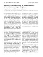
Solid State Semiconductor Lasers
GaAs (Hetrojunction) Lasers
These devices have been around since the
1960s and can produce very powerful light
pulses. Some devices are able to launch
light pulses in excess of 20 watts, which is
some 200 times more powerful than a
typical GaAlAs LED. But, these devices
can only be driven with duty cycles, less
than 0.1% (off time must be 1000 times
longer than on time). Also, their maximum
pulse width must be kept short (typically
less than 200 nanoseconds) even under
low pulse rate applications. However,
despite their limitations these devices can
be used in some voice transmitter systems
if some careful circuit designs are used.
As in most semiconductor lasers, the GaAs
laser does require a minimum current level
Figure 3d
(typically 10 to 20 amps) before it begins
emitting useable light. Such high operating currents demand more complicated drive circuits.
Despite a 10:1 sensitivity reduction, caused by the rather narrow emitted pulses (see receiver circuit
discussion), the more powerful light pulses available from GaAs lasers can increase the useful range
of a communications system by a factor of about 3, over a typical transmitter using a single LED. In
Optical Through-the-Air Communications Handbook -David A. Johnson, PE
Page 25 of 68