Design of microstrip patch antenna using defected ground
Bạn đang xem bản rút gọn của tài liệu. Xem và tải ngay bản đầy đủ của tài liệu tại đây (378.83 KB, 5 trang )
International Journal of Computer Applications (0975 – 8887)
Volume 67– No.15, April 2013
Design of Microstrip Patch Antenna using Defected
Ground Structure for WLAN Band
Sukhdeep Kaur
Student
Department of Electronics and communication
Lovely Professional University, Phagwara, India
ABSTRACT
This paper presents the Microstrip patch antenna for WLAN
applications. The microstrip antenna has a planar geometry
and it consists of a defected ground, a feed, a substrate, a
patch and a defected ground structure. The design with DGS
has been analysed and the simulation using the CST
Microwave Studio commercial software for WLAN band at
5.20 GHz frequency with corresponding bandwidth of 304
MHz to optimize antenna’s properties. Results show that the
designed antenna has favourable characteristics at this
frequency.
General Terms
Microstrip line feed and Microstrip Antenna.
Keywords
Neha Ahuja
Assistant Professor
Department of Electronics and communication
Lovely Professional University, Phagwara, India
2. GEOMETRY OF MICROSTRIP
PATCH ANTENNA
In this antenna, the substrate has the thickness of h=1.524 mm
and a relative permittivity r = 4.4. The Length and Width of
patch are 11.84 mm and 19.06 mm respectively and length
and width of substrate are 22.64 mm and 26.96 mm
respectively. The structure used for ground is defected ground
structure. The main concept behind the proposed antenna is to
implement DGS structure to enhance the bandwidth of the
designed antenna. Microstrip patch antenna can be fed by
different types of methods such as microstrip line feed,
aperture coupling, electromagnetic coupling, coaxial probe
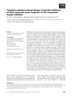
feed and coplanar waveguide (CPW). The DGS consists of the
two rectangular areas and one connecting slot in the ground
plane [6] as shown in figure 1.
DGS, WLAN Communication Standard, CST Microwave
Studio.
1. INTRODUCTION
The microstrip patch antenna is one of the most useful
antennas for low cost and compact design for RF applications
and wireless systems. In wireless mobile communication and
satellite applications, microstrip antenna has attracted much
interest because of their small size, low cost on mass
production, light weight, low profile and easy integration with
the other components [1-2]. The major drawback of
microstrip patch antenna is the narrow bandwidth. There are
many approaches that can be implemented in order to enhance
the bandwidth of the microstrip patch antenna. An individual
microstrip patch antenna has a typical gain of about 6 dB.
Several approaches have been used to enhance the bandwidth
by perturbing the higher order mode by interpolating surface
modification into patch geometry. Gain enhancement by
cutting rectangular hole on another inserted layer. A
symmetrical hole on the inserted layer is used which is the
major frequency in modern wireless communication era [3].
But the most unique technique to reduce the size of patch is to
defect the ground. While comparing the antenna with the
defected ground structure and the antenna without the
defected ground, the antenna having defected ground structure
reduces the size of antenna [4]. The percentage of reduction of
size depends upon the ground area that is defected. Defected
Ground Structure disturbs the shielded current distribution
that depends on the dimension and shape of the defect. The
current flow and the input impedance of antenna are then
influenced by the disturbance at shielded current distribution
due to the DGS structure. The DGS structure can also use to
control the excitation and the electromagnetic waves
propagating through the substrate layer [5]. In this paper,
microstrip antenna for WLAN applications at frequency 5.20
GHz (5.055 GHz to 5.360 GHz) is designed and simulated
using the CST Microwave Studio.
b
a
h
Figure 1: DGS
In this work, microstrip line (50 ohm) feed has been used. In
this design we have used a defected ground structure which
gives the very good resonance. Antenna is designed for the
resonating frequency of 5.20 GHz and is analyzed by using
the CST Microwave Studio software. For the designing of
rectangular microstrip patch antenna, the following
relationships are used to calculate the dimensions of the
rectangular microstrip patch antenna [7-8].
reff
r 1 r 1
h
2
2
W
1
2
(1)
The effective length is given by
Leff
c
2 fo reff
(2)
The length extension (ΔL) is given by
1
International Journal of Computer Applications (0975 – 8887)
Volume 67– No.15, April 2013
W
0.3 0.264
L
h
0.412
W
h
reff 0.258 0.8
h
reff
(3)
The actual length (L) of patch is obtained by:
L Leff 2L
fr
1
o
2 L r 2 L r
(4)
(5)
The width of the patch element (W) is given by:
W
1
2
2 fr o r 1
(6)
Lg 6h L
(7)
Wg 6h W
(8)
Where,
h = substrate thickness
L = length of patch
Leff = effective length
W = width of patch
c = speed of light
fo = resonant frequency
r = relative permittivity
eff = effective permittivity
Lg = Length of ground plane
Wg = Width of ground plane [7-8]
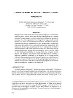
Figure 2(a): Front view geometry of designed antenna
Design frequency = 5.20 GHz
Substrate permittivity = 4.4
Thickness of substrate = 1.524 mm
Length of patch (L) = 11.84 mm
Width of patch (W) = 19.06 mm
Length of Ground (Lg) = 22.64 mm
Width of Ground (Wg) = 26.96 mm
3. DESIGN PARAMETERS
Figure 2(a) and 2(b) shows the front view geometry and the
designed structure of the designed microstrip patch antenna
with single band operation for the WLAN band on the CST
Microwave Studio software. The feed point location and the
dimensions for the designed antenna has been optimized so as
to get the better possible impedance match to the antenna.
Figure 2(b): Designed structure on CST microwave studio
2
International Journal of Computer Applications (0975 – 8887)
Volume 67– No.15, April 2013
4. STIMULATED RESULTS
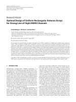
4.1 Return Loss
The S11 parameter for the proposed antenna was calculated
and the simulated return loss results are shown in Figure 3.
Return loss is a convenient way to characterize the input and
output of the signal sources or when the load is mismatched,
not all the available power from generator is delivered to the
load. This "loss" is termed as the return loss (RL) [10]. The
value of return loss is -40.302 dB in this proposed antenna.
The achieved return loss value is small enough and frequency
is very closed enough to the specified frequency band for 5.2
GHz WLAN applications. The value of return loss i.e. -40.302
dB shows that at the frequency point i.e. below the -10 dB
region there is good matching A negative value of return loss
shows that this antenna had not many losses while
transmitting the signals [10].
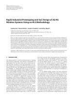
Figure 4: Bandwidth plot
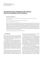
4.3 Smith Chart and VSWR
The achieved antenna impedance is 50 ohm as shown in
Figure 5, which is the required impedance. VSWR (Voltage
Standing Wave Ratio) is a measure of impedance mismatch.
The VSWR ratio of proposed antenna is 1:1.023 as shown in
Figure 6, which should lie in between 1 and 2.
Figure 3: Stimulated return loss curve
4.2 Bandwidth
The bandwidth at the resonating frequency of 5.20 GHz is 304
MHz with corresponding value of the return loss as -40.302
dB as shown in Figure 4. Several approaches have been used
to enhance the bandwidth of the antenna but in this design the
bandwidth of 304 MHz is achieved by using Defected Ground
Structure. The antenna covers the WLAN application standard
IEEE 802.11 (5.2 GHz band).
Figure 5: Curve showing antenna characteristic
impedance
3
International Journal of Computer Applications (0975 – 8887)
Volume 67– No.15, April 2013
4.5 Gain
Gain is a very important parameter of every antenna.
Basically, the gain is the ratio of the radiated field intensity by
test antenna to the radiated field intensity by the reference
antenna [9]. Antenna gain, usually expressed in dB, simply
refers to the direction of maximum radiation [10]. In this
study, the gain of the proposed antenna at frequency of 5.2
GHz is 4.642 dB as shown in Figure 8.
Figure 6: VSWR curve
4.4 Directivity
It is desirable to maximize the radiation pattern of the antenna
response in a fixed direction in order to transmit or receive
power. Likewise, the directivity is dependent only on the
shape of the radiation pattern [10]. The achieved directivity of
proposed antenna is 6.119 dBi at resonating frequency of 5.20
GHz as shown in figure 7. It shows that proposed antenna
radiates in omni-directional nature.
Figure 8: Gain of designed antenna
5. CONCLUSION
The designed single band microstrip patch antenna is
operating in the frequency band of 5.055 GHz - 5.360 GHz
covering 5.2 GHz WLAN communication standard. The
resultant bandwidth at 5.2 GHz frequency is around 304 MHz
with the corresponding value of return loss -40.302 dB which
shows that the impedance matching is good at this frequency.
The resultant gain of desired antenna is 4.642 dB which is not
so good but it can be increased by using gain enhancement
techniques and the directivity of the proposed antenna is 6.119
dBi which shows that the antenna radiates in omni-directional
nature. It has good impedance matching of 50 ohm. The
resultant bandwidth is good due to defected ground structure
but the size of the antenna is not very small. Work is going on
to achieve even best results.
6. ACKNOWLEDGMENTS
The authors are very thankful to the referees for their valuable
comments.
Figure 7: Directivity of designed antenna
4
International Journal of Computer Applications (0975 – 8887)
Volume 67– No.15, April 2013
7. REFERENCES
[1] Constantine A Balanis. 2005. Antenna Theory, Analysis
and Design. John Wiley & Sons Inc, 2nd Edition
(Reprint).
[2]
K. L. Wong. 2003. Compact and Broadband Microstrip
Antennas. John Wiley & Sons.
[3] Rampal Kushwaha, Prof. Kanchan Cecil, “Design and
analysis of gain for rectangular microstrip patch antenna
using symmetrical cuts”, International Journal of
Advance Technology & Engineering Research
(IJATER), November 2011.
[4] L. H. Weng, Y. C. Guo, X. W. Shi, and X. Q. Chen.
2008, “An Overview On Defected Ground Structure”,
Progress In Electromagnetics Research B, Vol. 7, 173–
189.
[5] Rajeshwar Lal Dua, Himanshu Singh, Neha Gambhir,
“2.45 GHz Microstrip Patch Antenna with Defected
Ground Structure for Bluetooth”, International Journal of
Soft Computing and Engineering (IJSCE) ISSN: 22312307, January 2012, Volume-1, Issue-6.
[6] Arya, A.K. Kartikeyan, M.V., Patnaik, A, “Efficiency
enhancement of microstrip patch antennas with Defected
Ground Structure”, IEEE proc. Recent Advanced in
Microwave theory and applications (MICROWAVE-08),
November 2008, pp.729–731.
[7] Neha ahuja, Rajesh khanna, Jaswinder Kaur, “Design of
Single Band Rectangular Patch Antenna for WLAN
Application”, International Conference on Recent
Advances and Future Trends in Information Technology
(iRAFIT2012) Proceedings published in International
Journal of Computer Applications® (IJCA) pp 29-31.
[8] Neha ahuja, Rajesh khanna, Jaswinder Kaur, “Dual Band
Defected Ground Microstrip Patch Antenna for
WLAN/WiMax and Satellite Application”, International
Journal of Computer Applications (0975 – 8887), June
2012, Volume 48– No.22.
[9] Deepak Sood, Gurpal singh, Chander Charu Tripathi,
Suresh Chander Sood, Pawan Joshi, “Design, Fabrication
and Characterization of microstrip square patch antenna
array for X-band applications”, Indian journal of pure
and applied Physics, August 2008, Vol. 46, pp. 593-597.
[10] Z. 1. Dafalla, W. T. Y. Kuan, A. M. Abdel Rahman, and
S. C. Shudakar, “Design of a Rectangular Microstrip
Patch Antenna at 1 GHz”, RF and Microwave
Conference, October 5 - 6, 2004, Subang, Selangor,
Malaysia.
5