Microstrip patch antenna with defected ground structure
Bạn đang xem bản rút gọn của tài liệu. Xem và tải ngay bản đầy đủ của tài liệu tại đây (893.76 KB, 5 trang )
International Journal of Computer Applications (0975 – 8887)
Volume 73– No.9, July 2013
Microstrip Patch Antenna with Defected Ground Structure
for Bandwidth Enhancement
Gurpreet Singh
Rajni
Ranjit Singh Momi
Research Scholar (M.Tech.)
SBSSTC, Ferozepur
Assoc. Prof.
SBSSTC, Ferozepur
H.O.D. (ECE Deptt.)
YRS Polytechnic, Moga
ABSTRACT
In this paper, a new Defected Ground Structure (DGS)
consisting of I-shape slot in ground has been presented to
enhance the bandwidth of the Microstrip Patch Antenna
(MPA). The parameters such as Bandwidth, Return loss and
VSWR are much improved in proposed antenna than simple
MPA without defected ground structure. Finite Element
Machine (FEM) based High Frequency Structure Simulator
(HFSS) software Version-13.0 is used to obtain the
performance parameters of the proposed antenna. A
comparison is also shown for the proposed antenna with the
antenna structure without defect. The proposed antenna
resonates in C-band at frequency of 6.0718 GHz with
bandwidth of 132.3 MHz. A very good return loss of -46.75
dB is obtained for I-Shaped Defected Ground Structure
(DGS). Also I-shaped DGS in the ground plane found to give
a size reduction of about 5%.
General Terms
Bandwidth (B.W.), Voltage Standing Wave Ratio (VSWR),
return loss (S11), gain and directivity.
Keywords
Defected Ground Structure (DGS), Microstrip Patch Antenna
(MPA).
1. INTRODUCTION
Recently, a growing demands of microwave and wireless
communication systems in various applications resulting in an
interest to improve antenna performances. Therefore, the
selection of microstrip antenna is suitable to apply at various
fields such as telecommunication, medical application,
satellite and military system. However, microstrip antenna has
its inherent shortcomings such as narrow bandwidth, typically
5% of centre frequency and half space radiation [1]. Many
kind of miniaturization techniques, such as using of dielectric
substrate of high permittivity [2], slot on the patch, DGS at
the ground plane or a combination of them have been
proposed and applied to microstrip patch antennas.
Conformal microstrip antennas are applied for a wide variety
of higher frequency, such as the cylindrical microstrip
antenna, has been paid more attention by many researchers [35], which can reduce the size, widen the radiation beam. The
surface wave restricts the wide use of microstrip antenna,
electromagnetic bandgap (EBG) or photonic bandgap (PBG)
structure is a method to reduce the surface waves, which
exhibit band-gap feature [6] too. EBG has been applied in the
field of antenna to improve the performance of antenna [712], such as suppression of surface wave propagation,
increasing the gain of antenna and improving the radiation
pattern by inserting the EBG structure into the substrate [1315]. However, in implementing EBG, a large area is needed to
implement the periodic patterns and it is also difficult to
define the unit element of EBG.
Defected ground structure (DGS) has similar microwave
circuit properties as EBG, it can also modify guided wave
properties to provide a band-pass or band-stop like filter and
can easily define the unit element. The geometry of DGS can
be one or few etched structure which is simpler and does not
need a large area to implement it [16]. DGS structure disturbs
the shield current distribution in the ground plane [17], [18],
which influences the input impedance and current flow of the
antenna.
Many shapes of DGS slot have been studied in planar
microsrip antenna designs [19-21], which provides many good
performances such as size reduction (resonant frequency
lower), impedance bandwidth enhancement (quality factor
lower) and gain increasing. The compact, broadband
microstrip antenna with defective ground plane has been
realized in [22]; the impedance bandwidth of the proposed
antenna could reach about 4.3 times that of the conventional
microstrip antenna. Several slots are embedded in the ground
of the microstrip antenna so that the size is reduced, the
impedance band and gain is enhanced [20]. By utilizing a slotload technique [22], the microstrip slot antenna excites two
resonant frequencies. By combining with a defective ground
plane, the bandwidth is augmented and the resonant frequency
is lowed simultaneously.
In this paper work, a notable ground structure named defected
ground structure (DGS) has recently been investigated and
found to be a simple and effective method to reduce the
antenna size. Proposed antenna design incorporates I-Shaped
Defected Ground Structure in ground plane. Etching this DGS
underneath the simple microstrip feedline, impedance
bandwidth broadening can be obtained.
2. ANTENNA DESIGN
Both MPA and proposed antennas are designed on Rogers
RT/Duroid 5880 (tm) substrate with thickness (hs) of 0.794
mm having relative permittivity (Ɛr) of 2.2. The patch has the
dimensions of 15.236 mm × 25.236 mm with height (hp) of
0.05 mm. The ground has the dimensions of 20 mm × 30 mm
with height (hg) of 0.05 mm. Antenna is excited with
microstrip feed having characteristics impedance of 50 Ω. The
feed has dimension of 2.382 mm × 2.2 mm with height (hf) of
0.05 mm. The complete geometry of simple MPA is shown in
Fig. 1.
In order to improve the Bandwidth and Return loss, ground is
defected with I-Shape slot. The width of slot along Y-axis is 3
mm and the length of slot along X-axis is 10 mm as shown in
Fig. 2. Also this slot made on ground helps in the reduction of
overall weight and size of proposed antenna.
14
International Journal of Computer Applications (0975 – 8887)
Volume 73– No.9, July 2013
minimum. For a specific resonant frequency (fr) and dielectric
constant of substrate ( r), the width (W), length (L) of patch
of MPA are expressed as follows:
W=
(1)
L = Le - ∆L
(2)
where, Le and ∆L are the effective and extended Length of
patch and are expressed as:
Fig 1: Geometry of simple MPA antenna
Le =
(3)
∆
(4)
where, e is the effective dielectric constant of substrate and is
expressed as:
(5)
Similar results for finite and infinite ground plane can be
obtained if the size of the ground plane is greater than the
patch dimensions by approximately six times the substrate
thickness all around the periphery [14]. Hence, for this design,
the ground plane dimensions would be given as:
Lg = 6 h + L
(6)
Wg = 6 h + W
(7)
where, “h” is the height of substrate. Lg and Wg are length and
width of ground plane respectively.
In order to improve the Bandwidth and Return loss, ground is
defected with I-Shape slot. Also this slot made on ground
helps in the reduction of overall weight and size of proposed
antenna.
3. RESULTS AND DISCUSSIONS
Fig 2: Geometry of G-shaped DGS antenna
Table 1 shows some common design parameters or
specifications for both antennas i.e. simple MPA and I-slot
DGS antenna.
Table 1. Common design specifications for both antennas
Sr.
No.
Specifications
Dimensions (mm) /
Values
1.
Ground (Lg×Wg×hg)
20×30×0.05
2.
Substrate (Ls×Ws×hs)
20×30×0.794
3.
Patch (LP×WP×hp)
15.236×25.236×0.05
4.
Feed (Lf×Wf×hf)
2.382×2.2×0.05
5.
Permittivity of substrate
material “Rogers
RT/Duroid 5880 tm” ( )
2.2
Finite Element Machine (FEM) based High Frequency
Structure Simulator (HFSS) software Version-13.0 package is
used to obtain the performance parameters of the proposed
antenna.
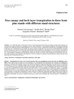
3.1 Return loss (S11) and bandwidth
It is evident from Fig. 3 that when I-shaped defect in ground
plane is introduced, the proposed antenna resonates in C-band
at resonant frequency fr = 6.0718 GHz. A very good return
loss of -46.75 dB at fr = 6.0718 GHz is obtained for this
structure. At this resonant frequency, it gives a maximum
bandwidth of 132.3 MHz (i.e. MX1 – MX2).
While the Fig. 4 depicts that MPA without slotting in ground
also resonates in the C-band but at resonant frequency fr =
6.2051 GHz. The bandwidth of the microstrip patch antenna
with same dimensions as mentioned above but without
slotting is 126.2 MHz at fr 6.2051 GHz. The value of return
loss (S11) obtained from MPA is -27.72 dB.
The Proposed antenna resonates at frequency (fr) of 6.0718
GHz. The resonant frequency, also called the center
frequency, is selected as the one at which the return loss is
15
International Journal of Computer Applications (0975 – 8887)
Volume 73– No.9, July 2013
Fig 3: Return loss (S11) of I-slot DGS antenna
Fig 6: VSWR Plot of MPA
3.3 Total gain
Fig. 7 shows the Polar plot for gain, obtained from I-shaped
DGS Antenna. The Total Gain provided by proposed antenna
at fr 6.0718 is 7.91 dB.
Fig 4: Return loss (S11) of MPA
Thus it has been concluded that with I-Shape DGS, the
bandwidth of the microstrip patch antenna (MPA) can be
increased by 6.1 MHz (i.e. 132.3 MHz – 126.2 MHz = 6.1
MHz).
3.2 VSWR
Fig. 5 shows VSWR plot of the proposed antenna. At
frequency of 6.0718 GHz, the VSWR is 1.009. As the value
of VSWR is approximately equal to 1 at resonant frequency
(fr), proposed antenna results in perfect impedance matching.
Fig 7: 3D Polar Plot of Total Gain of I-Slot DGS antenna
While the obtained gain, in case of MPA i.e. without defected
ground at resonant frequency fr= 6.2051 GHz is 7.96 dB as
shown in Fig. 8.
Fig 5: VSWR Plot of I-Shaped Antenna
While the VSWR, in case of simple MPA i.e. without
defected ground at resonating frequency fr= 6.2051 GHz is
1.085 as shown in Fig. 6.
Fig 8: 3D polar plot of Total Gain of simple MPA
16
International Journal of Computer Applications (0975 – 8887)
Volume 73– No.9, July 2013
3.4 Directivity
4. CONCLUSION
Fig. 9 shows the 3D Polar Plot of Total Directivity obtained
from I-shaped DGS Antenna. This figure shows that the Total
Directivity of the proposed antenna at fr = 6.0718 is 7.92 dB.
A novel antenna design working in C-band has been
successfully implemented in this paper. The bandwidth of the
microstrip patch antenna with same dimensions as mentioned
above but without slotting is 126.2 MHz at fr 6.2051 GHz
with return losses (S11 = -27.72 dB) as shown in Fig. 4. While
microstrip patch antenna with I-Shape DGS provides
bandwidth of 132.3 MHz and return losses reaches up to 46.75 dB as shown in Fig. 3. Thus it has been concluded that
with I-Shape DGS, the bandwidth of the microstrip patch
antenna is increased by 6.1 MHz. with reduction in ground
plane area by 5%.
The proposed antenna design is useful for satellite
communications as well as in RADAR.
5. REFERENCES
[1] Islam, Mohammad Tariqul, Mohammed Nazmus Shakib,
Norbahiah Misran, and Tiang Sew Sun. "Broadband
microstrip patch antenna." European Journal of
Scientific Research 27, no. 2 (2009): 174-180.
Fig 9: 3D Polar plot of total directivity of I-slot DGS
antenna
While the simulated directivity, in case of simple MPA i.e.
without defected ground at resonant frequency fr= 6.2051
GHz is 7.995 dB as shown in Fig. 10.
[2] Lo, Terry Kin-chung, and Yeongming Hwang.
"Microstrip antennas of very high permittivity for
personal communications." In 1997 Asia Pacific
Microwave Conference, pp. 253-256. 1997.
[3] Wong, Kin‐Lu, and Jin‐Sen Chen. "Cavity‐model
analysis of a slot‐coupled cylindrical‐rectangular
microstrip antenna." Microwave and Optical Technology
Letters 9, no. 3 (1995): 124-127.
[4]
Chen, Jin‐Sen, and Kin‐Lu Wong. "Input impedance
of a slot‐coupled cylindrical‐circular microstrip patch
antenna." Microwave and Optical Technology Letters 11,
no. 1 (1996): 21-24.
[5] Dahele, J. S., R. J. Mitchell, K. M. Luk, and K. F. Lee.
"Effect of curvature on characteristics of rectangular
patch antenna." Electronics Letters 23, no. 14 (1987):
748-749.
[6]
Fig 10: 3D polar plot of total directivity of MPA
Table 2 summarizes the obtained simulation features of the
designed antennas.
Table 2. Comparison of simulated results of both antennas
Sr.
No.
Parameters
MPA
Antenna
I-Shaped
DGS Antenna
1.
Resonating
Frequency (GHz)
6.2051
6.0718
2.
Bandwidth (MHz)
126.2
132.3
3.
Return Loss (dB)
-27.72
-46.75
4.
VSWR
1.085
1.009
5.
Gain
7.96
7.91
6.
Directivity
7.99
7.92
Yablonovitch, Eli. "Inhibited spontaneous emission in
solid-state physics and electronics." Physical review
letters 58, no. 20 (1987): 2059.
[7] Qu, D., L. Shafai, and A. Foroozesh. "Improving
microstrip patch antenna performance using EBG
substrates." IEE Proceedings-Microwaves, Antennas and
Propagation 153, no. 6 (2006): 558-563.
[8] Jin, Nanbo, Ang Yu, and Xuexia Zhang. "An enhanced
2×2 antenna array based on a dumbbell EBG
structure." Microwave
and
Optical
Technology
Letters 39, no. 5 (2003): 395-399.
[9] He, Wei, Ronghong Jin, Junping Geng, and Guoming
Yang. "2×2 Array with UC‐EBG ground for low RCS
and high gain." Microwave and optical technology
Letters 49, no. 6 (2007): 1418-1422.
[10] Geng, Jun-Ping, Jiajing Li, Rong-Hong Jin, Sheng Ye,
Xianling Liang, and Minzhu Li. "The development of
curved microstrip antenna with defected ground
structure." Progress In Electromagnetics Research 98
(2009): 53-73.
[11] Brown, E. R., C. D. Parker, and Eli Yablonovitch.
"Radiation properties of a planar antenna on a photoniccrystal substrate." JOSA B 10, no. 2 (1993): 404-407.
17
International Journal of Computer Applications (0975 – 8887)
Volume 73– No.9, July 2013
[12] Radisic, Vesna, Yongxi Qian, Roberto Coccioli, and
Tatsuo Itoh. "Novel 2-D photonic bandgap structure for
microstrip lines." Microwave and Guided Wave Letters,
IEEE 8, no. 2 (1998): 69-71.
[13] Beaky, Matthew M., John B. Burk, Henry O. Everitt,
Mansoor A. Haider, and Stephanos Venakides. "Twodimensional photonic crystal Fabry-Perot resonators with
lossy dielectrics." Microwave Theory and Techniques,
IEEE Transactions on 47, no. 11 (1999): 2085-2091.
[14] Qian, Yongxi, Dan Sievenpiper, Vesna Radisic, Eli
Yablonovitch, and Tatsuo Itoh. "A novel approach for
gain and bandwidth enhancement of patch antennas."
In Radio and Wireless Conference, 1998. RAWCON 98.
1998 IEEE, pp. 221-224. IEEE, 1998.
[15] Wang, Xiaojing, Yang Hao, and Peter S. Hall. "Dualband resonances of a patch antenna on UC-EBG
substrate." In Microwave Conference Proceedings, 2005.
APMC 2005. Asia-Pacific Conference Proceedings, vol.
1, pp. 4-pp. IEEE, 2005.
[16] Zulkifli, Fitri Yuli, Eko Tjipto Rahardjo, and Djoko
Hartanto. "Radiation properties enhancement of
triangular patch microstrip antenna array using
hexagonal defected ground structure." Progress In
Electromagnetics Research M 5 (2008): 101-109.
[17] Arya, A. K., M. V. Kartikeyan, and A. Patnaik.
"Efficiency enhancement of microstrip patch antenna
with defected ground structure." In Recent Advances in
Microwave
Theory
and
Applications,
2008.
IJCATM : www.ijcaonline.org
MICROWAVE 2008. International Conference on, pp.
729-731. IEEE, 2008.
[18] Zulkifli, Fitri Yuli, Eko Tjipto Rahardjo, and Djoko
Hartanto. "Mutual coupling reduction using dumbbell
defected ground structure for multiband microstrip
antenna array." Progress In Electromagnetics Research
Letters 13 (2010): 29-40.
[19] Lin, Xian-Chang, and Ling-Teng Wang. "A wideband
CPW-fed patch antenna with defective ground plane."
In Antennas and Propagation Society International
Symposium, 2004. IEEE, vol. 4, pp. 3717-3720. IEEE,
2004.
[20] Wong, K. L., J. S. Kuo, and T. W. Chiou. "Compact
microstrip antennas with slots loaded in the ground
plane." In Antennas and Propagation, 2001. Eleventh
International Conference on (IEE Conf. Publ. No. 480),
vol. 2, pp. 623-626. IET, 2001.
[21] Lin, Shun‐Yun, and Kin‐Lu Wong. "Effects of
slotted and photonic bandgap ground planes on the
characteristics of an air‐substrate annular‐ring patch
antenna in the TM21 mode." Microwave and Optical
Technology Letters 31, no. 1 (2001): 1-3.
[22] Geng, Jun-Ping, Jiajing Li, Rong-Hong Jin, Sheng Ye,
Xianling Liang, and Minzhu Li. "The development of
curved microstrip antenna with defected ground
structure." Progress In Electromagnetics Research 98
(2009): 53-73
18