IMPROVING BANDWIDTH RECTANGULAR PATCH ANTENNA USING DIFF
Bạn đang xem bản rút gọn của tài liệu. Xem và tải ngay bản đầy đủ của tài liệu tại đây (387.59 KB, 6 trang )
VOL. 6, NO. 4, APRIL 2011
ISSN 1819-6608
ARPN Journal of Engineering and Applied Sciences
©2006-2011 Asian Research Publishing Network (ARPN). All rights reserved.
www.arpnjournals.com
IMPROVING BANDWIDTH RECTANGULAR PATCH ANTENNA USING
DIFFERENT THICKNESS OF DIELECTRIC SUBSTRATE
Ali A. Dheyab Al-Sajee and Karim A. Hamad
Department of Electronic and Communication, College of Engineering, Al-Nahrain University, Iraq
E-Mail:
ABSTRACT
Microstrip patch antenna has some drawbacks of low efficiency, narrow band (<5%), and surface wave losses. In
this paper the solution method was used different thickness of dielectric substrate (h = 4, 6 and 8) mm to increase
bandwidth, the simulated results for rectangular give bandwidth of (200 MHz) in case (h = 6mm). A rectangular microstrip
patch antenna that meets the requirement of operation at (2.4 GHz), the proposed configurations are simulated and
analyzed using microwave office 2000 software package. The VSWR, input impedance, radiation patterns and S11
performance are used for the analysis of the different configurations. Feed point on the patch that gives a good match of 50
ohm, input impedance was found by a method of trial and error.
Keywords: Microstrip patch antenna, bandwidth improvement, performance, dielectric substrate.
1. INTRODUCTION
A micostrip patch antenna has the advantages of
low cost, light weight, and low profile planner
configuration. However, they suffer from the disadvantage
of low operating bandwidth [1-2]. Bandwidth improves as
the substrate thickness is increased, or the dielectric
constant is reduced, but these trends are limited by an
inductive impedance offset that increases with thickness.
A logical approach, therefore, is to use a thick substrate or
replacing the substrate by air or thick foam, the dielectric
constants are usually in the range of (2.2≤ εr ≤12) [3-4].
This paper presents the use of transmission line method to
analyze the rectangular micro strip antenna [5]. RMPA
operating of resonance frequency (2.4GHz) for TM10
mode, with the coaxial probe feed used the antenna is
matched by choosing the proper feed position [6].
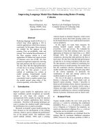
RMPA is characterized by its length L, width W
and thickness h, as shown in Figure-1.
2. TRANSMISSION LINE ANALYSIS METHOD
RMPA
In this model the MSA can be represented by two
slots of width (W) and height (h) separated by
transmission line of length (L).
The width of the patch can be calculated from the
following equation [8].
---------- (1)
The effective dielectric constant (εeff) is less than
(εr) because the fringing field around the periphery of the
patch is not confined to the dielectric speared in the air
also.
----- (2)
For TM10 Mode the length of the patch must be
less than (λ /2)
This difference in the length (∆L) which is given
empirically by [9].
Figure-1. Structure of a rectangular microstrip patch
antenna.
It is of a very thin thickness h (h << λo , usually
0.003 λo ≤ h ≤ 0.05 λo) where λo is free space wavelength
above a ground plane [7].
For rectangular patch, the length L of the element
is usually
λo / 3 < L < λo / 2.
--- (3)
---------- (4)
Where c=speed of light, Leff = effective length.
Fr=resonance frequency, εeff = effective dielectric
constant.
-------- (5)
For a rectangular microstrip patch antenna, the
resonance frequency for any TMmn mode is given by
James and Hall [10] as:
16
VOL. 6, NO. 4, APRIL 2011
ISSN 1819-6608
ARPN Journal of Engineering and Applied Sciences
©2006-2011 Asian Research Publishing Network (ARPN). All rights reserved.
www.arpnjournals.com
----- (6)
Where m, n = 0, 1, 2 --- wave number at m,n mode,
c=speed of light.
3. DESIGN CONSIDERATION OF RMPA
The designer should have step by step procedure.
Step one
Substrate selection
The first step in the design is to choose a suitable
dielectric substrate of appropriate thickness h and loss
tangent. A thicker substrate, besides being mechanically
strong it will increase the radiated power, reduce the
conductor loss and improve impedance bandwidth [11].
Step two
Width and length parameters
A larger patch width increases the power radiated
and thus gives decreased resonant resistance, increased
BW and increased radiation efficiency. With proper
excitation one may choose a patch width W greater than
patch length. It has been suggested that 1 < W/ L < 2 [12,
13].
In case of microstrip antenna, it is proportional to
its quality factor Q and given by [13] as:
-------- (7)
The percentage bandwidth of the rectangular
patch microstrip antenna in terms of patch dimensions and
substrates parameters is given as follows [13].
--------- (8)
4. DESIGN RECTANGULAR PATCH ANTENNA
The resonant frequency of the antenna must be
selected properly.
The WIFI applications use the frequency range
from (2-3 GHz).
(fo) selected for this design is (2.4 GHz).
The dielectric material selected
For the design is droid which has a dielectric
constant of (εr = 4.4).
The height of the dielectric substrate is selected
as h = 6 mm.
The essential parameters for the design are:
fo = 2.4 GHz, εr = 4.4 (FR4 material), loss tangent =
0.0005 and h = 6 mm.
The transmission line model will be used to
design the antenna.
4.1 Calculation of the width (W)
The width of the equation (1) gives at fo= 2.4
GHz, εr = 4.4, W= 38 mm.
4.2 Calculation of effective dielectric constant (εeff)
Equation (2) gives the effective dielectric
constant as: For εr = 4.4 and fo = 2.4 GHz, it gives: εeff =
3.7.
4.3 Calculation of the length extension (∆L)
Equation (3) gives the length extension as:
For εeff = 3.7, fo = 2.4 GHz, W = 38 mm and h = 6 mm it
gives: ∆L= 2.44mm.
4.4 Calculation of the effective length
(Leff): Equation (4) gives the effective length as:
For εeff = 3.7 and fo = 2.4GHz it gives: Leff = 32.5mm.
4.5 Calculation of actual length of patch (L)
The actual length is obtained by equation (5) as:
L = 27.6 mm.
4.6 Calculation of ground plane dimensions
(Lg and Wg) by [14] would be given as
For L = 27.6 mm, W = 38 mm and h = 6 mm
Lg = L + 6h
---------- (9)
then
--------- (10)
then
Lg = 63.6 mm.
Wg = W + 6h
Wg = 74 mm.
Where h is the substrate thickness, λo is the wavelength in
the substrate, εr is the dielectric constant of substrate, W,
L is the width and length of patch dimension.
4.7 Determination of feed point location (Xf, Yf)
Using the equation provided in Bahl/Bhartia [15].
Feed point location where the input impedance is
nearly 50 ohm is
Yf
= W/2
---------- (11)
Xf
= L /(2 √ εeff)
----- -----(12)
17
VOL. 6, NO. 4, APRIL 2011
ISSN 1819-6608
ARPN Journal of Engineering and Applied Sciences
©2006-2011 Asian Research Publishing Network (ARPN). All rights reserved.
www.arpnjournals.com
then Yf = 19mm along the width, and Xf = 7.174 mm
along the length. When trial and error are used, it was
found the best impedance match at feed point location is
2.15625mm of the left edge of the patch, the distance is
11.875mm is of the upper of the length patch, at an input
impedance of (50 + j 0.119) ohms.
The software used to model and simulate the
MPA is the Microwave Office 2000 package.
The number of divisions is 128 divisions X cell
size = 0.43125mm and Y cell size = 0.59375mm.
The top dielectric layer of the enclosure is set to
have the properties of air with thickness = 10mm.
5. SIMULATION RESULTS
Re (Z IN [1 ] )
wi t h o u t s l o t f o r h 6 m m A L
Z input
Re(ZIN(1)) (Ohm)
RMPA h 4mm
2.4016 GHz
42.474 Ohm
Im(ZIN(1)) (Ohm)
RMPA h 4mm
150
Z input
I m (Z IN [1 ] )
wi t h o u t s l o t f o r h 6 m m A L
100
80
100
2.4 GHz
50
60
50
40
0
20
2.3969 GHz
0.1523 Ohm
2.4 GHz
0.137
0.119
0
-50
2
2.2
2.4
2.6
Frequency (GHz)
2.8
2
3
2.5
Frequency (GHz)
(a)
3
(b)
Z input
150
Re(ZIN[1])
RMPA h 8mm
Im(ZIN[1])
RMPA h 8mm
100
2.4 GHz
50
50
2.4 GHz
26.5
0
2
2.5
Frequency (GHz)
3
(c)
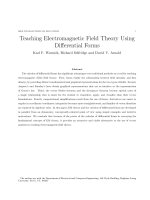
Figure-2. The input impedance of the antenna with different
thickness (4, 6 and 8mm).
18
VOL. 6, NO. 4, APRIL 2011
ISSN 1819-6608
ARPN Journal of Engineering and Applied Sciences
©2006-2011 Asian Research Publishing Network (ARPN). All rights reserved.
www.arpnjournals.com
20
10
-4
0
-4
40
0
40
Mag Max
2
30
30
0
10
20
-10
0
-3
-3
50
0
-5
H field
E_Theta(0,1)
RMPA h 4mm
Mag Max
2
-2 0
-20
-10
0
E field
E_Phi(90,1)
RMPA h 4mm
50
-5
0
0
60
60
-6
0
-6
0
70
70
- 70
-7 0
80
80
-80
-80
90
90
-90
-90
100
100
-100
-100
1 10
1 10
0
-1 1
- 11
0
12
0
12
0
20
13
0
0
40
-1
0
-1 6
0
-170
-16
-170
-1
50
-1
0
1 60
170
0.5
Per Div
180
160
Mag Min
0
0
15
0
15
180
170
0.5
Per Div
0
14
0
40
13
30
-1
14
3
-1
2
-1
0
-1
50
-1
Mag Min
0
(a)
20
10
40
40
0
0
-4
-4
50
-5
0
Mag Max
2
30
30
20
-10
0
0
-3
-3
-20
-2 0
-10
10
0
H field
E_Theta(0,1)
RMPA h 6mm
Mag Max
2
0
E field
E_Phi(90,1)[*]
RMPA h 6mm
50
-5
0
60
60
-6
0
-6
0
70
70
-7 0
-7 0
80
80
-80
-80
90
90
-90
-90
100
100
-100
-100
1 10
- 11
1 10
0
- 11
0
12
0
12
0
0
13
0
0
-170
-1
4
0
- 16
0
-1 6
160
-170
40
-1
0
0
15
0.5
Per Div
170
Mag Min
0
180
1 60
-1
50
14
0
0
15
180
170
0.5
Per Div
13
0
30
-1
14
30
-1
20
-1
-1
50
2
-1
Mag Min
0
(b)
0
10
Mag Max
2
30
20
20
10
0
30
-3
0
-4
0
-4
40
40
0
0
50
50
-5
0
0
60
60
-6
-10
Mag Max
2
-20
-20
-10
-3
-5
H field
E_Theta(0,1)
RMPA h8mm
E field
E_Phi(90,1)
RMPA h8mm
-6
0
0
70
70
-70
-70
80
80
-80
-80
90
90
-90
-90
100
100
-100
-100
110
110
0
-11
- 11
12
0
20
-1
13
0
-1
40
50
0
-170
-170
-16
50
-1
0
170
180
160
0
160
-16
0
15
-1
40
13
0
0
14
15
180
170
0.5
Per Div
Mag Min
0
0
20
30
-1
0
14
30
-1
0.5
Per Div
12
-1
-1
0
Mag Min
0
(c)
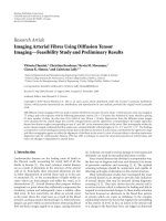
Figure-3. The radiation pattern E-plane, H-plane of the antenna with different dielectric
thickness (4, 6 and 8) mm.
19
VOL. 6, NO. 4, APRIL 2011
ISSN 1819-6608
ARPN Journal of Engineering and Applied Sciences
©2006-2011 Asian Research Publishing Network (ARPN). All rights reserved.
www.arpnjournals.com
Return loss
0
2.3972 GHz
-21.759 dB
-5
-10
Return losses
DB(|S(1,1)|)
RMPA h 4mm
DB(|S[1,1]|)
without slot for h 6mm AL
0
-10
2.3 GHz
-10.1
-20
2.4735 GHz
-10.007 dB
2.3184 GHz
-10.001 dB
-15
-30
-20
-40
-25
-50
2.5 GHz
-10.1
2.4 GHz
-57.8
-60
-30
2
2.2
2.4
2.6
Frequency (GHz)
2.8
3
2
2.5
Frequency (GHz)
(a)
3
(b)
DB(|S[1,1]|)
RMPA h 8mm
Return losses
-2
-4
2.4 GHz
-11.9
-6
-8
2.44 GHz
-10
2.29 GHz
-10
-10
-12
2
2.5
Frequency (GHz)
3
(c)
Figure-4. The return losses of the antenna with different
thickness (4mm, 6mm and 8mm).
The bandwidth can be calculated from the return
losses (RL) plot.
With Figure-4a, the simulated impedance bandwidth of
(155.1 MHz 6.46 %) from (2.3184) GHz to (2.4735) GHz
is achieved at (-10dB) return losses (VSWR ≤ 2).
With Figure-4b, the simulated impedance bandwidth
(200MHz 8.33 %) from (2.3) GHz to (2.5) GHz
achieved at – (10dB) return losses (VSWR ≤ 2).
With Figure-4c, the simulated impedance bandwidth
(150MHz 6.25 %) from (2.29) GHz to (2.44) GHz
achieved at (-10dB) return losses (VSWR ≤ 2).
Table-1. Effect of the dielectric thickness on antenna performance.
Item
Dielectric
thickness
(h mm)
1
4
2
6
3
8
Patch
specification
( mm)
W=38mm
∆L=1.8
εeff = 3.83
L=28.336mm
W=38mm
∆L=2.625
εeff = 3.7
L=27.6mm
W=38mm
∆L=3.415
εeff = 3.6
L=26.08mm
fo
(GHz)
Return
losses
BW
(MHz)
BW
(%)
2.4
-21.759 dB
155.1
6.46 %
2.4
-57.8dB
200
8.33 %
2.4
-11.9dB
150
6.25 %
From Table-1 it can be noticed that as the thickness of the substrate increases the bandwidth increases also.
20
of
is
of
is
VOL. 6, NO. 4, APRIL 2011
ISSN 1819-6608
ARPN Journal of Engineering and Applied Sciences
©2006-2011 Asian Research Publishing Network (ARPN). All rights reserved.
www.arpnjournals.com
6. CONCLUSIONS
It appears that from the present work, the
possibility of using MW-office package for determine the
proper location of a proper feed.
For substrate thickness (4mm) the first design
antenna had a (155.1) MHz bandwidth (6.46 % of central
frequency). Whereas when the thickness was used (6mm),
the bandwidth increased to be (200) MHz, which gives a
percent of bandwidth to the centre frequency of (8.33%)
that means the bandwidth improvement approximately
(45) MHz. whereas when the thickness was used (h =
8mm) the bandwidth decreased to be 150MHz.
[11] A.A. Deshmukh and G. Kumar. 2005. Compact
broadband E-shaped microstrip. ELECTRONICS
LETTERS. 41(18).
[12] Komsan Kanjanasit. Novel Design of a Wide and
Improved U-Slot on Rectangular Patch Using
Additional Loading Slots.
[13] Kumar G and Ray K.P. 2003. Broadband Microstrip
antennas. Artech House, USA.
[14] C. A. Balanis. 1997. Antenna Theory, Analysis and
Design. John Wiley and Sons, New York.
REFERENCES
[1] A.K Bhattachar jee, S.R Bhadra, D.R. Pooddar and
S.K. Chowdhury. 1989. Equivalence of impedance
and radiation properties of square and circular
microstrip patch antennas. IEE Proc. 136(Pt, H, 4):
338-342.
[15] I.J. Bahl and P. Bhartia. 1982. Microstrip Antennas.
Artech House Inc. IN.
[2] R. G. Voughan. 1988. Two-port higher mode circular
microstrip ntennas. IEEE, Trans. Antennas Propagat.
36(3): 309-321.
[3] T Huynh and K.F. Lee. 1995. Single layer single patch
wideband microstrip patch antenna. Electronic letters.
L (31): 1310-1311.
[4] Constantine A. Balanis. 2005. ANTENNA THEORY
ANALYSIS AND DESIGN. 3rd Edition. John Wiley
and Sons.
[5] V Zachou. 2004. Transmission line model Design
Formula for Microstrip Antenna with Slots. IEEE.
[6] Prabhakar H.V. 2007. U.K.
LETTERS. 2nd August. 43(16).
ELECTRONICS
[7] Jani Ollikainen and Pertti Vainikainen. 1998.
Radiation and Bandwidth Characteristics of Two
Planar
Multistrip
Antennas
for
Mobile
Communication Systems. IEEE Vehicular Technology
Conference. Ottawa, Ontario, Canada. 2: 1186-1190.
[8] Lorena I. Basilio. 2001. The Dependence of the Input
Impedance on Feed Position of Probe and Microstrip
Line-Fed patch Antennas. IEEE Transaction on
Antennas and Propagation. 49(1).
[9] J. R. James and P. S. Hall. 1989. Handbook of
Microstrip Antennas. London, Peregrinus.
[10] Ray K. P. 1999. Broadband, Dual Frequency and
Compact Microstrip Antennas. Ph. D. Thesis. Indian
Institute of Technology, Bombay, India.
21