tài liệu tham khảo tiếng anh chuyên ngành điệnđiện tử
Bạn đang xem bản rút gọn của tài liệu. Xem và tải ngay bản đầy đủ của tài liệu tại đây (5.16 MB, 328 trang )
PIC16F882/883/884/886/887
Data Sheet
28/40/44-Pin, Enhanced Flash-Based 8-Bit
CMOS Microcontrollers with
nanoWatt Technology
© 2009 Microchip Technology Inc.
DS41291F
Note the following details of the code protection feature on Microchip devices:
•
Microchip products meet the specification contained in their particular Microchip Data Sheet.
•
Microchip believes that its family of products is one of the most secure families of its kind on the market today, when used in the
intended manner and under normal conditions.
•
There are dishonest and possibly illegal methods used to breach the code protection feature. All of these methods, to our
knowledge, require using the Microchip products in a manner outside the operating specifications contained in Microchip’s Data
Sheets. Most likely, the person doing so is engaged in theft of intellectual property.
•
Microchip is willing to work with the customer who is concerned about the integrity of their code.
•
Neither Microchip nor any other semiconductor manufacturer can guarantee the security of their code. Code protection does not
mean that we are guaranteeing the product as “unbreakable.”
Code protection is constantly evolving. We at Microchip are committed to continuously improving the code protection features of our
products. Attempts to break Microchip’s code protection feature may be a violation of the Digital Millennium Copyright Act. If such acts
allow unauthorized access to your software or other copyrighted work, you may have a right to sue for relief under that Act.
Information contained in this publication regarding device
applications and the like is provided only for your convenience
and may be superseded by updates. It is your responsibility to
ensure that your application meets with your specifications.
MICROCHIP MAKES NO REPRESENTATIONS OR
WARRANTIES OF ANY KIND WHETHER EXPRESS OR
IMPLIED, WRITTEN OR ORAL, STATUTORY OR
OTHERWISE, RELATED TO THE INFORMATION,
INCLUDING BUT NOT LIMITED TO ITS CONDITION,
QUALITY, PERFORMANCE, MERCHANTABILITY OR
FITNESS FOR PURPOSE. Microchip disclaims all liability
arising from this information and its use. Use of Microchip
devices in life support and/or safety applications is entirely at
the buyer’s risk, and the buyer agrees to defend, indemnify and
hold harmless Microchip from any and all damages, claims,
suits, or expenses resulting from such use. No licenses are
conveyed, implicitly or otherwise, under any Microchip
intellectual property rights.
Trademarks
The Microchip name and logo, the Microchip logo, Accuron,
dsPIC, KEELOQ, KEELOQ logo, MPLAB, PIC, PICmicro,
PICSTART, rfPIC, SmartShunt and UNI/O are registered
trademarks of Microchip Technology Incorporated in the
U.S.A. and other countries.
FilterLab, Linear Active Thermistor, MXDEV, MXLAB,
SEEVAL, SmartSensor and The Embedded Control Solutions
Company are registered trademarks of Microchip Technology
Incorporated in the U.S.A.
Analog-for-the-Digital Age, Application Maestro, CodeGuard,
dsPICDEM, dsPICDEM.net, dsPICworks, dsSPEAK, ECAN,
ECONOMONITOR, FanSense, In-Circuit Serial
Programming, ICSP, ICEPIC, Mindi, MiWi, MPASM, MPLAB
Certified logo, MPLIB, MPLINK, mTouch, nanoWatt XLP,
PICkit, PICDEM, PICDEM.net, PICtail, PIC32 logo, PowerCal,
PowerInfo, PowerMate, PowerTool, REAL ICE, rfLAB, Select
Mode, Total Endurance, TSHARC, WiperLock and ZENA are
trademarks of Microchip Technology Incorporated in the
U.S.A. and other countries.
SQTP is a service mark of Microchip Technology Incorporated
in the U.S.A.
All other trademarks mentioned herein are property of their
respective companies.
© 2009, Microchip Technology Incorporated, Printed in the
U.S.A., All Rights Reserved.
Printed on recycled paper.
Microchip received ISO/TS-16949:2002 certification for its worldwide
headquarters, design and wafer fabrication facilities in Chandler and
Tempe, Arizona; Gresham, Oregon and design centers in California
and India. The Company’s quality system processes and procedures
are for its PIC® MCUs and dsPIC® DSCs, KEELOQ® code hopping
devices, Serial EEPROMs, microperipherals, nonvolatile memory and
analog products. In addition, Microchip’s quality system for the design
and manufacture of development systems is ISO 9001:2000 certified.
DS41291F-page ii
© 2009 Microchip Technology Inc.
PIC16F882/883/884/886/887
28/40/44-Pin Flash-Based, 8-Bit CMOS Microcontrollers with
nanoWatt Technology
High-Performance RISC CPU:
Peripheral Features:
• Only 35 Instructions to Learn:
- All single-cycle instructions except branches
• Operating Speed:
- DC – 20 MHz oscillator/clock input
- DC – 200 ns instruction cycle
• Interrupt Capability
• 8-Level Deep Hardware Stack
• Direct, Indirect and Relative Addressing modes
• 24/35 I/O Pins with Individual Direction Control:
- High current source/sink for direct LED drive
- Interrupt-on-Change pin
- Individually programmable weak pull-ups
- Ultra Low-Power Wake-up (ULPWU)
• Analog Comparator Module with:
- Two analog comparators
- Programmable on-chip voltage reference
(CVREF) module (% of VDD)
- Fixed voltage reference (0.6V)
- Comparator inputs and outputs externally
accessible
- SR Latch mode
- External Timer1 Gate (count enable)
• A/D Converter:
- 10-bit resolution and 11/14 channels
• Timer0: 8-bit Timer/Counter with 8-bit
Programmable Prescaler
• Enhanced Timer1:
- 16-bit timer/counter with prescaler
- External Gate Input mode
- Dedicated low-power 32 kHz oscillator
• Timer2: 8-bit Timer/Counter with 8-bit Period
Register, Prescaler and Postscaler
• Enhanced Capture, Compare, PWM+ Module:
- 16-bit Capture, max. resolution 12.5 ns
- Compare, max. resolution 200 ns
- 10-bit PWM with 1, 2 or 4 output channels,
programmable “dead time”, max. frequency
20 kHz
- PWM output steering control
• Capture, Compare, PWM Module:
- 16-bit Capture, max. resolution 12.5 ns
- 16-bit Compare, max. resolution 200 ns
- 10-bit PWM, max. frequency 20 kHz
• Enhanced USART Module:
- Supports RS-485, RS-232, and LIN 2.0
- Auto-Baud Detect
- Auto-Wake-Up on Start bit
• In-Circuit Serial ProgrammingTM (ICSPTM) via Two
Pins
• Master Synchronous Serial Port (MSSP) Module
supporting 3-wire SPI (all 4 modes) and I2C™
Master and Slave Modes with I2C Address Mask
Special Microcontroller Features:
• Precision Internal Oscillator:
- Factory calibrated to ±1%
- Software selectable frequency range of
8 MHz to 31 kHz
- Software tunable
- Two-Speed Start-up mode
- Crystal fail detect for critical applications
- Clock mode switching during operation for
power savings
• Power-Saving Sleep mode
• Wide Operating Voltage Range (2.0V-5.5V)
• Industrial and Extended Temperature Range
• Power-on Reset (POR)
• Power-up Timer (PWRT) and Oscillator Start-up
Timer (OST)
• Brown-out Reset (BOR) with Software Control
Option
• Enhanced Low-Current Watchdog Timer (WDT)
with On-Chip Oscillator (software selectable
nominal 268 seconds with full prescaler) with
software enable
• Multiplexed Master Clear with Pull-up/Input Pin
• Programmable Code Protection
• High Endurance Flash/EEPROM Cell:
- 100,000 write Flash endurance
- 1,000,000 write EEPROM endurance
- Flash/Data EEPROM retention: > 40 years
• Program Memory Read/Write during run time
• In-Circuit Debugger (on board)
Low-Power Features:
• Standby Current:
- 50 nA @ 2.0V, typical
• Operating Current:
- 11 μA @ 32 kHz, 2.0V, typical
- 220 μA @ 4 MHz, 2.0V, typical
• Watchdog Timer Current:
- 1 μA @ 2.0V, typical
© 2009 Microchip Technology Inc.
DS41291F-page 1
PIC16F882/883/884/886/887
Device
Program
Memory
Data Memory
I/O
10-bit A/D
(ch)
ECCP/
CCP
EUSART
MSSP
Comparators
Timers
8/16-bit
128
24
11
1/1
1
1
2
2/1
256
24
11
1/1
1
1
2
2/1
256
256
35
14
1/1
1
1
2
2/1
8192
368
256
24
11
1/1
1
1
2
2/1
8192
368
256
35
14
1/1
1
1
2
2/1
Flash
(words)
SRAM
(bytes)
EEPROM
(bytes)
PIC16F882
2048
128
PIC16F883
4096
256
PIC16F884
4096
PIC16F886
PIC16F887
DS41291F-page 2
© 2009 Microchip Technology Inc.
PIC16F882/883/884/886/887
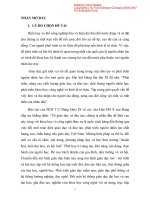
Pin Diagrams – PIC16F882/883/886, 28-Pin PDIP, SOIC, SSOP
1
2
3
4
5
6
7
8
9
10
11
12
13
14
RE3/MCLR/VPP
RA0/AN0/ULPWU/C12IN0RA1/AN1/C12IN1RA2/AN2/VREF-/CVREF/C2IN+
RA3/AN3/VREF+/C1IN+
RA4/T0CKI/C1OUT
RA5/AN4/SS/C2OUT
VSS
RA7/OSC1/CLKIN
RA6/OSC2/CLKOUT
RC0/T1OSO/T1CKI
RC1/T1OSI/CCP2
RC2/P1A/CCP1
RC3/SCK/SCL
TABLE 1:
PIC16F882/883/886
28-pin PDIP, SOIC, SSOP
28
27
26
25
24
23
22
21
20
19
18
17
16
15
RB7/ICSPDAT
RB6/ICSPCLK
RB5/AN13/T1G
RB4/AN11/P1D
RB3/AN9/PGM/C12IN2RB2/AN8/P1B
RB1/AN10/P1C/C12IN3RB0/AN12/INT
VDD
VSS
RC7/RX/DT
RC6/TX/CK
RC5/SDO
RC4/SDI/SDA
PIC16F882/883/886 28-PIN SUMMARY (PDIP, SOIC, SSOP)
I/O
Pin
Analog
Comparators
Timers
ECCP
EUSART
MSSP
Interrupt Pull-up
Basic
RA0
2
AN0/ULPWU
C12IN0-
—
—
—
—
—
—
—
RA1
3
AN1
C12IN1-
—
—
—
—
—
—
—
RA2
4
AN2
C2IN+
—
—
—
—
—
—
VREF-/CVREF
RA3
5
AN3
C1IN+
—
—
—
—
—
—
VREF+
RA4
6
—
C1OUT
T0CKI
—
—
—
—
—
—
RA5
7
AN4
C2OUT
—
—
—
SS
—
—
—
RA6
10
—
—
—
—
—
—
—
—
OSC2/CLKOUT
OSC1/CLKIN
RA7
9
—
—
—
—
—
—
—
—
RB0
21
AN12
—
—
—
—
—
IOC/INT
Y
—
RB1
22
AN10
C12IN3-
—
P1C
—
—
IOC
Y
—
RB2
23
AN8
—
—
P1B
—
—
IOC
Y
—
RB3
24
AN9
C12IN2-
—
—
—
—
IOC
Y
PGM
RB4
25
AN11
—
—
P1D
—
—
IOC
Y
—
RB5
26
AN13
—
T1G
—
—
—
IOC
Y
—
RB6
27
—
—
—
—
—
—
IOC
Y
ICSPCLK
RB7
28
—
—
—
—
—
—
IOC
Y
ICSPDAT
RC0
11
—
—
T1OSO/T1CKI
—
—
—
—
—
—
RC1
12
—
—
T1OSI
CCP2
—
—
—
—
—
RC2
13
—
—
—
CCP1/P1A
—
—
—
—
—
—
RC3
14
—
—
—
—
—
SCK/SCL
—
—
RC4
15
—
—
—
—
—
SDI/SDA
—
—
—
RC5
16
—
—
—
—
—
SDO
—
—
—
RC6
17
—
—
—
—
TX/CK
—
—
—
—
RC7
18
—
—
—
—
RX/DT
—
—
—
—
RE3
1
—
—
—
—
—
—
—
Y(1)
MCLR/VPP
—
20
—
—
—
—
—
—
—
—
VDD
—
8
—
—
—
—
—
—
—
—
VSS
—
19
—
—
—
—
—
—
—
—
VSS
Note 1:
Pull-up activated only with external MCLR configuration.
© 2009 Microchip Technology Inc.
DS41291F-page 3
PIC16F882/883/884/886/887
Pin Diagrams – PIC16F882/883/886, 28-Pin QFN
28
27
26
25
24
23
22
RA1/AN1/C12IN1RA0/AN0/ULPWU/C12IN0RE3/MCLR/VPP
RB7/ICSPDAT
RB6/ICSPCLK
RB5/AN13/T1G
RB4/AN11/P1D
28-pin QFN
8
9
10
11
12
13
14
1
21
2
20
3
19
4 PIC16F882/883/886 18
5
17
6
16
15
7
RB3/AN9/PGM/C12IN2RB2/AN8/P1B
RB1/AN10/P1C/C12IN3RB0/AN12/INT
VDD
VSS
RC7/RX/DT
RC0/T1OSO/T1CKI
RC1/T1OSI/CCP2
RC2/P1A/CCP1
RC3/SCK/SCL
RC4/SDI/SDA
RC5/SDO
RC6/TX/CK
RA2/AN2/VREF-/CVREF/C2IN+
RA3/AN3/VREF+/C1IN+
RA4/T0CKI/C1OUT
RA5/AN4/SS/C2OUT
VSS
RA7/OSC1/CLKIN
RA6/OSC2/CLKOUT
DS41291F-page 4
© 2009 Microchip Technology Inc.
PIC16F882/883/884/886/887
TABLE 2:
PIC16F882/883/886 28-PIN SUMMARY (QFN)
I/O
Pin
Analog
Comparators
Timers
ECCP
EUSART
MSSP
Interrupt Pull-up
Basic
RA0
27
AN0/ULPWU
C12IN0-
—
—
—
—
—
—
—
RA1
28
AN1
C12IN1-
—
—
—
—
—
—
—
RA2
1
AN2
C2IN+
—
—
—
—
—
—
VREF-/CVREF
RA3
2
AN3
C1IN+
—
—
—
—
—
—
VREF+
—
RA4
3
—
C1OUT
T0CKI
—
—
—
—
—
RA5
4
AN4
C2OUT
—
—
—
SS
—
—
—
RA6
7
—
—
—
—
—
—
—
—
OSC2/CLKOUT
RA7
6
—
—
—
—
—
—
—
—
OSC1/CLKIN
RB0
18
AN12
—
—
—
—
—
IOC/INT
Y
—
RB1
19
AN10
C12IN3-
—
P1C
—
—
IOC
Y
—
RB2
20
AN8
—
—
P1B
—
—
IOC
Y
—
RB3
21
AN9
C12IN2-
—
—
—
—
IOC
Y
PGM
—
RB4
22
AN11
—
—
P1D
—
—
IOC
Y
RB5
23
AN13
—
T1G
—
—
—
IOC
Y
—
RB6
24
—
—
—
—
—
—
IOC
Y
ICSPCLK
RB7
25
—
—
—
—
—
—
IOC
Y
ICSPDAT
RC0
8
—
—
T1OSO/T1CKI
—
—
—
—
—
—
RC1
9
—
—
T1OSI
CCP2
—
—
—
—
—
RC2
10
—
—
—
CCP1/P1A
—
—
—
—
—
RC3
11
—
—
—
—
—
SCK/SCL
—
—
—
RC4
12
—
—
—
—
—
SDI/SDA
—
—
—
RC5
13
—
—
—
—
—
SDO
—
—
—
RC6
14
—
—
—
—
TX/CK
—
—
—
—
RC7
15
—
—
—
—
RX/DT
—
—
—
—
RE3
26
—
—
—
—
—
—
—
Y(1)
MCLR/VPP
—
17
—
—
—
—
—
—
—
—
VDD
—
5
—
—
—
—
—
—
—
—
VSS
—
16
—
—
—
—
—
—
—
—
VSS
Note 1:
Pull-up activated only with external MCLR configuration.
© 2009 Microchip Technology Inc.
DS41291F-page 5
PIC16F882/883/884/886/887
Pin Diagrams – PIC16F884/887, 40-Pin PDIP
RE3/MCLR/VPP
RA0/AN0/ULPWU/C12IN0RA1/AN1/C12IN1RA2/AN2/VREF-/CVREF/C2IN+
RA3/AN3/VREF+/C1IN+
RA4/T0CKI/C1OUT
RA5/AN4/SS/C2OUT
RE0/AN5
RE1/AN6
RE2/AN7
VDD
VSS
RA7/OSC1/CLKIN
RA6/OSC2/CLKOUT
RC0/T1OSO/T1CKI
RC1/T1OSI/CCP2
RC2/P1A/CCP1
RC3/SCK/SCL
RD0
RD1
DS41291F-page 6
1
2
3
4
5
6
7
8
9
10
11
12
13
14
15
16
17
18
19
20
PIC16F884/887
40-pin PDIP
40
39
38
37
36
35
34
33
32
31
30
29
28
27
26
25
24
23
22
21
RB7/ICSPDAT
RB6/ICSPCLK
RB5/AN13/T1G
RB4/AN11
RB3/AN9/PGM/C12IN2RB2/AN8
RB1/AN10/C12IN3RB0/AN12/INT
VDD
VSS
RD7/P1D
RD6/P1C
RD5/P1B
RD4
RC7/RX/DT
RC6/TX/CK
RC5/SDO
RC4/SDI/SDA
RD3
RD2
© 2009 Microchip Technology Inc.
PIC16F882/883/884/886/887
TABLE 3:
PIC16F884/887 40-PIN SUMMARY (PDIP)
I/O
Pin
Analog
Comparators
Timers
ECCP
EUSART
MSSP
RA0
2
AN0/ULPWU
C12IN0-
—
—
—
—
Interrupt Pull-up
—
—
Basic
RA1
3
AN1
C12IN1-
—
—
—
—
—
—
—
RA2
4
AN2
C2IN+
—
—
—
—
—
—
VREF-/CVREF
RA3
5
AN3
C1IN+
—
—
—
—
—
—
VREF+
RA4
6
—
C1OUT
T0CKI
—
—
—
—
—
—
RA5
7
AN4
C2OUT
—
—
—
SS
—
—
—
RA6
14
—
—
—
—
—
—
—
—
OSC2/CLKOUT
—
RA7
13
—
—
—
—
—
—
—
—
OSC1/CLKIN
RB0
33
AN12
—
—
—
—
—
IOC/INT
Y
—
RB1
34
AN10
C12IN3-
—
—
—
—
IOC
Y
—
RB2
35
AN8
—
—
—
—
—
IOC
Y
—
RB3
36
AN9
C12IN2-
—
—
—
—
IOC
Y
PGM
RB4
37
AN11
—
—
—
—
—
IOC
Y
—
RB5
38
AN13
—
T1G
—
—
—
IOC
Y
—
RB6
39
—
—
—
—
—
—
IOC
Y
ICSPCLK
RB7
40
—
—
—
—
—
—
IOC
Y
ICSPDAT
RC0
15
—
—
T1OSO/T1CKI
—
—
—
—
—
—
RC1
16
—
—
T1OSI
CCP2
—
—
—
—
—
RC2
17
—
—
—
CCP1/P1A
—
—
—
—
—
RC3
18
—
—
—
—
—
SCK/SCL
—
—
—
RC4
23
—
—
—
—
—
SDI/SDA
—
—
—
—
RC5
24
—
—
—
—
—
SDO
—
—
RC6
25
—
—
—
—
TX/CK
—
—
—
—
RC7
26
—
—
—
—
RX/DT
—
—
—
—
RD0
19
—
—
—
—
—
—
—
—
—
—
RD1
20
—
—
—
—
—
—
—
—
RD2
21
—
—
—
—
—
—
—
—
—
RD3
22
—
—
—
—
—
—
—
—
—
RD4
27
—
—
—
—
—
—
—
—
—
—
RD5
28
—
—
—
P1B
—
—
—
—
RD6
29
—
—
—
P1C
—
—
—
—
—
RD7
30
—
—
—
P1D
—
—
—
—
—
RE0
8
AN5
—
—
—
—
—
—
—
—
RE1
9
AN6
—
—
—
—
—
—
—
—
RE2
10
AN7
—
—
—
—
—
—
—
—
RE3
1
—
—
—
—
—
—
—
Y(1)
MCLR/VPP
—
11
—
—
—
—
—
—
—
—
VDD
—
32
—
—
—
—
—
—
—
—
VDD
—
12
—
—
—
—
—
—
—
—
VSS
—
31
—
—
—
—
—
—
—
—
VSS
Note 1:
Pull-up activated only with external MCLR configuration.
© 2009 Microchip Technology Inc.
DS41291F-page 7
PIC16F882/883/884/886/887
Pin Diagrams – PIC16F884/887, 44-Pin QFN
PIC16F884/887
33
32
31
30
29
28
27
26
25
24
23
12
13
14
15
16
17
18
19
20
21
22
1
2
3
4
5
6
7
8
9
10
11
RA6/OSC2/CLKOUT
RA7/OSC1/CLKIN
VSS
VSS
NC
VDD
RE2/AN7
RE1/AN6
RE0/AN5
RA5/AN4/SS/C2OUT
RA4/T0CKI/C1OUT
RB3/AN9/PGM/C12IN2NC
RB4/AN11
RB5/AN13/T1G
RB6/ICSPCLK
RB7/ICSPDAT
RE3/MCLR/VPP
RA0/AN0/ULPWU/C12IN0RA1/AN1/C12IN1RA2/AN2/VREF-/CVREF/C2IN+
RA3/AN3//VREF+/C1IN+
RC7/RX/DT
RD4
RD5/P1B
RD6/P1C
RD7/P1D
VSS
VDD
VDD
RB0/AN12/INT
RB1/AN10/C12IN3RB2/AN8
44
43
42
41
40
39
38
37
36
35
34
RC6/TX/CK
RC5/SDO
RC4/SDI/SDA
RD3
RD2
RD1
RD0
RC3/SCK/SCL
RC2/P1A/CCP1
RC1/T1OSCI/CCP2
RC0/T1OSO/T1CKI
44-pin QFN
DS41291F-page 8
© 2009 Microchip Technology Inc.
PIC16F882/883/884/886/887
TABLE 4:
PIC16F884/887 44-PIN SUMMARY (QFN)
I/O
Pin
Analog
Comparators
Timers
ECCP
EUSART
MSSP
RA0
19
AN0/ULPWU
C12IN0-
—
—
—
—
Interrupt Pull-up
—
—
Basic
RA1
20
AN1
C12IN1-
—
—
—
—
—
—
—
RA2
21
AN2
C2IN+
—
—
—
—
—
—
VREF-/CVREF
RA3
22
AN3
C1IN+
—
—
—
—
—
—
VREF+
RA4
23
—
C1OUT
T0CKI
—
—
—
—
—
—
RA5
24
AN4
C2OUT
—
—
—
SS
—
—
—
RA6
33
—
—
—
—
—
—
—
—
OSC2/CLKOUT
RA7
32
—
—
—
—
—
—
—
—
OSC1/CLKIN
RB0
9
AN12
—
—
—
—
—
IOC/INT
Y
—
RB1
10
AN10
C12IN3-
—
—
—
—
IOC
Y
—
RB2
11
AN8
—
—
—
—
—
IOC
Y
—
—
RB3
12
AN9
C12IN2-
—
—
—
—
IOC
Y
PGM
RB4
14
AN11
—
—
—
—
—
IOC
Y
—
RB5
15
AN13
—
T1G
—
—
—
IOC
Y
—
RB6
16
—
—
—
—
—
—
IOC
Y
ICSPCLK
RB7
17
—
—
—
—
—
—
IOC
Y
ICSPDAT
RC0
34
—
—
T1OSO/T1CKI
—
—
—
—
—
—
RC1
35
—
—
T1OSI
CCP2
—
—
—
—
—
RC2
36
—
—
—
CCP1/P1A
—
—
—
—
—
RC3
37
—
—
—
—
—
SCK/SCL
—
—
—
RC4
42
—
—
—
—
—
SDI/SDA
—
—
—
—
RC5
43
—
—
—
—
—
SDO
—
—
RC6
44
—
—
—
—
TX/CK
—
—
—
—
RC7
1
—
—
—
—
RX/DT
—
—
—
—
RD0
38
—
—
—
—
—
—
—
—
—
—
RD1
39
—
—
—
—
—
—
—
—
RD2
40
—
—
—
—
—
—
—
—
—
RD3
41
—
—
—
—
—
—
—
—
—
RD4
2
—
—
—
—
—
—
—
—
—
—
RD5
3
—
—
—
P1B
—
—
—
—
RD6
4
—
—
—
P1C
—
—
—
—
—
RD7
5
—
—
—
P1D
—
—
—
—
—
RE0
25
AN5
—
—
—
—
—
—
—
—
RE1
26
AN6
—
—
—
—
—
—
—
—
RE2
27
AN7
—
—
—
—
—
—
—
—
RE3
18
—
—
—
—
—
—
—
Y(1)
MCLR/VPP
—
7
—
—
—
—
—
—
—
—
VDD
—
8
—
—
—
—
—
—
—
—
VDD
—
28
—
—
—
—
—
—
—
—
VDD
—
6
—
—
—
—
—
—
—
—
VSS
—
30
—
—
—
—
—
—
—
—
VSS
—
31
—
—
—
—
—
—
—
—
VSS
—
13
—
—
—
—
—
—
—
—
NC (no connect)
—
29
—
—
—
—
—
—
—
—
NC (no connect)
Note 1:
Pull-up activated only with external MCLR configuration.
© 2009 Microchip Technology Inc.
DS41291F-page 9
PIC16F882/883/884/886/887
Pin Diagrams – PIC16F884/887, 44-Pin TQFP
PIC16F884/887
33
32
31
30
29
28
27
26
25
24
23
12
13
14
15
16
17
18
19
20
21
22
1
2
3
4
5
6
7
8
9
10
11
NC
RC0/T1OSO/T1CKI
RA6/OSC2/CLKOUT
RA7/OSC1/CLKIN
VSS
VDD
RE2/AN7
RE1/AN6
RE0/AN5
RA5/AN4/SS/C2OUT
RA4/T0CKI/C1OUT
NC
NC
RB4/AN11
RB5/AN13/T1G
RB6/ICSPCLK
RB7/ICSPDAT
RE3/MCLR/VPP
RA0/AN0/ULPWU/C12IN0RA1/AN1/C12IN1RA2/AN2/VREF-/CVREF/C2IN+
RA3/AN3//VREF+/C1IN+
RC7/RX/DT
RD4
RD5/P1B
RD6/P1C
RD7/P1D
VSS
VDD
RB0/AN12/INT
RB1/AN10/C12IN3RB2/AN8
RB3/AN9/PGM/C12IN2-
44
43
42
41
40
39
38
37
36
35
34
RC6/TX/CK
RC5/SDO
RC4/SDI/SDA
RD3
RD2
RD1
RD0
RC3/SCK/SCL
RC2/P1A/CCP1
RC1/T1OSCI/CCP2
NC
44-pin TQFP
DS41291F-page 10
© 2009 Microchip Technology Inc.
PIC16F882/883/884/886/887
TABLE 5:
PIC16F884/887 44-PIN SUMMARY (TQFP)
I/O
Pin
Analog
Comparators
Timers
ECCP
EUSART
MSSP
RA0
19
AN0/ULPWU
C12IN0-
—
—
—
—
Interrupt Pull-up
—
—
Basic
RA1
20
AN1
C12IN1-
—
—
—
—
—
—
—
RA2
21
AN2
C2IN+
—
—
—
—
—
—
VREF-/CVREF
RA3
22
AN3
C1IN+
—
—
—
—
—
—
VREF+
RA4
23
—
C1OUT
T0CKI
—
—
—
—
—
—
RA5
24
AN4
C2OUT
—
—
—
SS
—
—
—
RA6
31
—
—
—
—
—
—
—
—
OSC2/CLKOUT
RA7
30
—
—
—
—
—
—
—
—
OSC1/CLKIN
RB0
8
AN12
—
—
—
—
—
IOC/INT
Y
—
RB1
9
AN10
C12IN3-
—
—
—
—
IOC
Y
—
RB2
10
AN8
—
—
—
—
—
IOC
Y
—
RB3
11
AN9
C12IN2-
—
—
—
—
IOC
Y
PGM
RB4
14
AN11
—
—
—
—
—
IOC
Y
—
RB5
15
AN13
—
T1G
—
—
—
IOC
Y
—
RB6
16
—
—
—
—
—
—
IOC
Y
ICSPCLK
—
RB7
17
—
—
—
—
—
—
IOC
Y
ICSPDAT
RC0
32
—
—
T1OSO/T1CKI
—
—
—
—
—
—
RC1
35
—
—
T1OSI
CCP2
—
—
—
—
—
RC2
36
—
—
—
CCP1/P1A
—
—
—
—
—
RC3
37
—
—
—
—
—
SCK/SCL
—
—
—
RC4
42
—
—
—
—
—
SDI/SDA
—
—
—
—
RC5
43
—
—
—
—
—
SDO
—
—
RC6
44
—
—
—
—
TX/CK
—
—
—
—
RC7
1
—
—
—
—
RX/DT
—
—
—
—
RD0
38
—
—
—
—
—
—
—
—
—
—
RD1
39
—
—
—
—
—
—
—
—
RD2
40
—
—
—
—
—
—
—
—
—
RD3
41
—
—
—
—
—
—
—
—
—
RD4
2
—
—
—
—
—
—
—
—
—
—
RD5
3
—
—
—
P1B
—
—
—
—
RD6
4
—
—
—
P1C
—
—
—
—
—
RD7
5
—
—
—
P1D
—
—
—
—
—
RE0
25
AN5
—
—
—
—
—
—
—
—
RE1
26
AN6
—
—
—
—
—
—
—
—
RE2
27
AN7
—
—
—
—
—
—
—
—
RE3
18
—
—
—
—
—
—
—
Y(1)
MCLR/VPP
—
7
—
—
—
—
—
—
—
—
VDD
—
28
—
—
—
—
—
—
—
—
VDD
—
6
—
—
—
—
—
—
—
—
VSS
—
13
—
—
—
—
—
—
—
—
NC (no connect)
—
29
—
—
—
—
—
—
—
—
VSS
—
34
—
—
—
—
—
—
—
—
NC (no connect)
—
33
—
—
—
—
—
—
—
—
NC (no connect)
—
12
—
—
—
—
—
—
—
—
NC (no connect)
Note 1:
Pull-up activated only with external MCLR configuration.
© 2009 Microchip Technology Inc.
DS41291F-page 11
PIC16F882/883/884/886/887
Table of Contents
1.0 Device Overview ........................................................................................................................................................................ 13
2.0 Memory Organization ................................................................................................................................................................. 21
3.0 I/O Ports ..................................................................................................................................................................................... 39
4.0 Oscillator Module (With Fail-Safe Clock Monitor)....................................................................................................................... 61
5.0 Timer0 Module ........................................................................................................................................................................... 73
6.0 Timer1 Module with Gate Control............................................................................................................................................... 76
7.0 Timer2 Module ........................................................................................................................................................................... 81
8.0 Comparator Module.................................................................................................................................................................... 83
9.0 Analog-to-Digital Converter (ADC) Module ................................................................................................................................ 99
10.0 Data EEPROM and Flash Program Memory Control ............................................................................................................... 111
11.0 Enhanced Capture/Compare/PWM Module ............................................................................................................................. 123
12.0 Enhanced Universal Synchronous Asynchronous Receiver Transmitter (EUSART) ............................................................... 151
13.0 Master Synchronous Serial Port (MSSP) Module .................................................................................................................... 179
14.0 Special Features of the CPU .................................................................................................................................................... 209
15.0 Instruction Set Summary .......................................................................................................................................................... 231
16.0 Development Support............................................................................................................................................................... 241
17.0 Electrical Specifications............................................................................................................................................................ 245
18.0 DC and AC Characteristics Graphs and Tables ....................................................................................................................... 273
19.0 Packaging Information.............................................................................................................................................................. 301
Appendix A: Data Sheet Revision History.......................................................................................................................................... 313
Appendix B: Migrating from other PIC® Devices ............................................................................................................................... 313
Index .................................................................................................................................................................................................. 315
The Microchip Web Site ..................................................................................................................................................................... 323
Customer Change Notification Service .............................................................................................................................................. 323
Customer Support .............................................................................................................................................................................. 323
Reader Response .............................................................................................................................................................................. 324
Product Identification System............................................................................................................................................................. 325
TO OUR VALUED CUSTOMERS
It is our intention to provide our valued customers with the best documentation possible to ensure successful use of your Microchip
products. To this end, we will continue to improve our publications to better suit your needs. Our publications will be refined and
enhanced as new volumes and updates are introduced.
If you have any questions or comments regarding this publication, please contact the Marketing Communications Department via
E-mail at or fax the Reader Response Form in the back of this data sheet to (480) 792-4150. We
welcome your feedback.
Most Current Data Sheet
To obtain the most up-to-date version of this data sheet, please register at our Worldwide Web site at:
You can determine the version of a data sheet by examining its literature number found on the bottom outside corner of any page.
The last character of the literature number is the version number, (e.g., DS30000A is version A of document DS30000).
Errata
An errata sheet, describing minor operational differences from the data sheet and recommended workarounds, may exist for current
devices. As device/documentation issues become known to us, we will publish an errata sheet. The errata will specify the revision of
silicon and revision of document to which it applies.
To determine if an errata sheet exists for a particular device, please check with one of the following:
• Microchip’s Worldwide Web site;
• Your local Microchip sales office (see last page)
When contacting a sales office, please specify which device, revision of silicon and data sheet (include literature number) you are
using.
Customer Notification System
Register on our web site at www.microchip.com to receive the most current information on all of our products.
DS41291F-page 12
© 2009 Microchip Technology Inc.
PIC16F882/883/884/886/887
1.0
DEVICE OVERVIEW
The PIC16F882/883/884/886/887 is covered by this
data sheet. The PIC16F882/883/886 is available in 28pin PDIP, SOIC, SSOP and QFN packages. The
PIC16F884/887 is available in a 40-pin PDIP and 44pin QFN and TQFP packages. Figure 1-1 shows the
block diagram of PIC16F882/883/886 and Figure 1-2
shows a block diagram of the PIC16F884/887 device.
Table 1-1 and Table 1-2 show the corresponding pinout
descriptions.
© 2009 Microchip Technology Inc.
DS41291F-page 13
PIC16F882/883/884/886/887
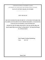
FIGURE 1-1:
PIC16F882/883/886 BLOCK DIAGRAM
Configuration
PORTA
13
8
Data Bus
RA0
RA1
RA2
RA3
RA4
RA5
RA6
RA7
Program Counter
Flash
2K(2)/4K(1)/
8K X 14
Program
Memory
Program
Bus
RAM
128(2)/256(1)/
368 Bytes
File
Registers
8-Level Stack
(13-Bit)
14
RAM Addr
PORTB
RB0
RB1
RB2
RB3
RB4
RB5
RB6
RB7
9
Addr MUX
Instruction Reg
7
Direct Addr
Indirect
Addr
8
FSR Reg
PORTC
STATUS Reg
RC0
RC1
RC2
RC3
RC4
RC5
RC6
RC7
8
3
MUX
Power-up
Timer
Instruction
Decode and
Control
Oscillator
Start-up Timer
ALU
PORTE
Power-on
Reset
OSC1/CLKIN
Timing
Generation
8
Watchdog
Timer
W Reg
Brown-out
Reset
OSC2/CLKOUT
RE3
CCP2
Internal
Oscillator
Block
CCP2
MCLR
VDD
VSS
SS
SCK/SCL
SDI/SDA
SDO
P1D
P1C
T1CKI
P1B
T1G
T0CKI
RX/DT
T1OSO
TX/CK
Timer1
32 kHz
Oscillator
T1OSI
CCP1/P1A
In-Circuit
Debugger
(ICD)
Master Synchronous
VREF+
VREF-
Note
1:
2:
DS41291F-page 14
Timer2
EUSART
ECCP
Analog-To-Digital Converter
(ADC)
2 Analog Comparators
and Reference
C1IN+
C12IN0C12IN1C12IN2C12IN3C1OUT
C2IN+
C2OUT
Timer1
AN0
AN1
AN2
AN3
AN4
AN8
AN9
AN10
AN11
AN12
AN13
Timer0
PIC16F883 only.
PIC16F882 only.
Serial Port (MSSP)
VREF+
VREFCVREF
8
EEDATA
128(2)/
256 Bytes
Data
EEPROM
EEADDR
© 2009 Microchip Technology Inc.
PIC16F882/883/884/886/887
PIC16F884/PIC16F887 BLOCK DIAGRAM
Configuration
PORTA
13
8
Data Bus
RA0
RA1
RA2
RA3
RA4
RA5
RA6
RA7
Program Counter
Flash
4K(1)/8K X 14
Program
Memory
Program
Bus
RAM
256(1)/368 Bytes
File
Registers
8-Level Stack
(13-Bit)
PORTB
14
RAM Addr
RB0
RB1
RB2
RB3
RB4
RB5
RB6
RB7
9
Addr MUX
Instruction Reg
7
Direct Addr
Indirect
Addr
8
FSR Reg
STATUS Reg
PORTC
RC0
RC1
RC2
RC3
RC4
RC5
RC6
RC7
8
3
MUX
Power-up
Timer
Instruction
Decode and
Control
Oscillator
Start-up Timer
ALU
Power-on
Reset
OSC1/CLKIN
Timing
Generation
PORTD
8
Watchdog
Timer
W Reg
CCP2
Brown-out
Reset
OSC2/CLKOUT
RD0
RD1
RD2
RD3
RD4
RD5
RD6
RD7
Internal
Oscillator
Block
CCP2
MCLR
VDD
PORTE
VSS
RE0
RE1
RE2
RE3
SCK/SCL
SDI/SDA
SDO
P1D
P1C
T1CKI
P1B
T1G
T0CKI
RX/DT
T1OSO
TX/CK
Timer1
32 kHz
Oscillator
T1OSI
CCP1/P1A
In-Circuit
Debugger
(ICD)
SS
FIGURE 1-2:
Master Synchronous
Timer1
VREF+
VREF-
Timer2
AN0
AN1
AN2
AN3
AN4
AN5
AN6
AN7
AN8
AN9
AN10
AN11
AN12
AN13
Analog-To-Digital Converter
(ADC)
Note
1:
EUSART
ECCP
2 Analog Comparators
and Reference
C1IN+
C12IN0C12IN1C12IN2C12IN3C1OUT
C2IN+
C2OUT
Timer0
Serial Port (MSSP)
VREF+
VREFCVREF
8
EEDATA
256 Bytes
Data
EEPROM
EEADDR
PIC16F884 only.
© 2009 Microchip Technology Inc.
DS41291F-page 15
PIC16F882/883/884/886/887
TABLE 1-1:
PIC16F882/883/886 PINOUT DESCRIPTION
Name
RA0/AN0/ULPWU/C12IN0-
RA1/AN1/C12IN1-
RA2/AN2/VREF-/CVREF/C2IN+
RA3/AN3/VREF+/C1IN+
RA4/T0CKI/C1OUT
RA5/AN4/SS/C2OUT
RA6/OSC2/CLKOUT
RA7/OSC1/CLKIN
RB0/AN12/INT
RB1/AN10/P1C/C12IN3-
RB2/AN8/P1B
Legend:
Function
Input
Type
RA0
TTL
Description
CMOS General purpose I/O.
AN0
AN
—
A/D Channel 0 input.
ULPWU
AN
—
Ultra Low-Power Wake-up input.
—
Comparator C1 or C2 negative input.
C12IN0-
AN
RA1
TTL
AN1
AN
C12IN1-
AN
RA2
TTL
CMOS General purpose I/O.
—
A/D Channel 1 input.
—
Comparator C1 or C2 negative input.
CMOS General purpose I/O.
AN2
AN
—
A/D Channel 2.
VREF-
AN
—
A/D Negative Voltage Reference input.
CVREF
—
AN
Comparator Voltage Reference output.
C2IN+
AN
—
Comparator C2 positive input.
RA3
TTL
—
General purpose I/O.
AN3
AN
—
A/D Channel 3.
VREF+
AN
—
Programming voltage.
C1IN+
AN
—
Comparator C1 positive input.
RA4
TTL
T0CKI
ST
C1OUT
—
CMOS General purpose I/O.
—
Timer0 clock input.
CMOS Comparator C1 output.
RA5
TTL
AN4
AN
—
A/D Channel 4.
SS
ST
—
Slave Select input.
CMOS General purpose I/O.
C2OUT
—
RA6
TTL
OSC2
—
XTAL
CLKOUT
—
CMOS FOSC/4 output.
RA7
TTL
OSC1
XTAL
CMOS Comparator C2 output.
CMOS General purpose I/O.
Master Clear with internal pull-up.
CMOS General purpose I/O.
—
Crystal/Resonator.
—
External clock input/RC oscillator connection.
CLKIN
ST
RB0
TTL
AN12
AN
—
A/D Channel 12.
INT
ST
—
External interrupt.
RB1
TTL
AN10
AN
P1C
—
C12IN3-
AN
RB2
TTL
AN8
AN
P1B
—
AN = Analog input or output
TTL = TTL compatible input
HV = High Voltage
DS41291F-page 16
Output
Type
CMOS General purpose I/O. Individually controlled interrupt-on-change.
Individually enabled pull-up.
CMOS General purpose I/O. Individually controlled interrupt-on-change.
Individually enabled pull-up.
—
A/D Channel 10.
CMOS PWM output.
—
Comparator C1 or C2 negative input.
CMOS General purpose I/O. Individually controlled interrupt-on-change.
Individually enabled pull-up.
—
A/D Channel 8.
CMOS PWM output.
CMOS = CMOS compatible input or output
OD = Open Drain
ST
= Schmitt Trigger input with CMOS levels
XTAL = Crystal
© 2009 Microchip Technology Inc.
PIC16F882/883/884/886/887
TABLE 1-1:
PIC16F882/883/886 PINOUT DESCRIPTION (CONTINUED)
Name
RB3/AN9/PGM/C12IN2-
RB4/AN11/P1D
RB5/AN13/T1G
RB6/ICSPCLK
RB7/ICSPDAT
RC0/T1OSO/T1CKI
RC1/T1OSI/CCP2
RC2/P1A/CCP1
RC3/SCK/SCL
RC4/SDI/SDA
RC5/SDO
RC6/TX/CK
RC7/RX/DT
RE3/MCLR/VPP
Function
Input
Type
RB3
TTL
Output
Type
Description
CMOS General purpose I/O. Individually controlled interrupt-on-change.
Individually enabled pull-up.
AN9
AN
—
PGM
ST
—
A/D Channel 9.
Low-voltage ICSP™ Programming enable pin.
C12IN2-
AN
—
Comparator C1 or C2 negative input.
RB4
TTL
AN11
AN
P1D
—
RB5
TTL
AN13
AN
—
A/D Channel 13.
T1G
ST
—
Timer1 Gate input.
RB6
TTL
CMOS General purpose I/O. Individually controlled interrupt-on-change.
Individually enabled pull-up.
—
A/D Channel 11.
CMOS PWM output.
CMOS General purpose I/O. Individually controlled interrupt-on-change.
Individually enabled pull-up.
CMOS General purpose I/O. Individually controlled interrupt-on-change.
Individually enabled pull-up.
ICSPCLK
ST
RB7
TTL
CMOS General purpose I/O. Individually controlled interrupt-on-change.
Individually enabled pull-up.
—
ICSPDAT
ST
CMOS ICSP™ Data I/O.
RC0
ST
CMOS General purpose I/O.
T1OSO
—
CMOS Timer1 oscillator output.
T1CKI
ST
—
Serial Programming Clock.
Timer1 clock input.
RC1
ST
T1OSI
ST
CMOS General purpose I/O.
CCP2
ST
CMOS Capture/Compare/PWM2.
RC2
ST
CMOS General purpose I/O.
P1A
—
CMOS PWM output.
—
Timer1 oscillator input.
CCP1
ST
CMOS Capture/Compare/PWM1.
RC3
ST
CMOS General purpose I/O.
SCK
ST
CMOS SPI clock.
SCL
ST
OD
I2C™ clock.
RC4
ST
SDI
ST
CMOS General purpose I/O.
—
SPI data input.
SDA
ST
OD
I2C data input/output.
RC5
ST
CMOS General purpose I/O.
SDO
—
CMOS SPI data output.
RC6
ST
CMOS General purpose I/O.
TX
—
CMOS EUSART asynchronous transmit.
CK
ST
CMOS EUSART synchronous clock.
RC7
ST
CMOS General purpose I/O.
RX
ST
DT
ST
RE3
TTL
—
General purpose input.
MCLR
ST
—
Master Clear with internal pull-up.
Programming voltage.
—
EUSART asynchronous input.
CMOS EUSART synchronous data.
VPP
HV
—
VSS
VSS
Power
—
Ground reference.
VDD
VDD
Power
—
Positive supply.
Legend:
AN = Analog input or output
TTL = TTL compatible input
HV = High Voltage
© 2009 Microchip Technology Inc.
CMOS = CMOS compatible input or output
OD = Open Drain
ST
= Schmitt Trigger input with CMOS levels
XTAL = Crystal
DS41291F-page 17
PIC16F882/883/884/886/887
TABLE 1-2:
PIC16F884/887 PINOUT DESCRIPTION
Name
RA0/AN0/ULPWU/C12IN0-
RA1/AN1/C12IN1-
RA2/AN2/VREF-/CVREF/C2IN+
RA3/AN3/VREF+/C1IN+
RA4/T0CKI/C1OUT
RA5/AN4/SS/C2OUT
RA6/OSC2/CLKOUT
RA7/OSC1/CLKIN
RB0/AN12/INT
RB1/AN10/C12IN3-
Function
Input
Type
RA0
TTL
AN0
AN
CMOS General purpose I/O.
—
A/D Channel 0 input.
ULPWU
AN
—
Ultra Low-Power Wake-up input.
AN
—
Comparator C1 or C2 negative input.
RA1
TTL
AN1
AN
C12IN1-
AN
RA2
TTL
CMOS General purpose I/O.
—
A/D Channel 1 input.
—
Comparator C1 or C2 negative input.
CMOS General purpose I/O.
AN2
AN
—
A/D Channel 2.
VREF-
AN
—
A/D Negative Voltage Reference input.
CVREF
—
AN
Comparator Voltage Reference output.
C2IN+
AN
—
Comparator C2 positive input.
RA3
TTL
AN3
AN
CMOS General purpose I/O.
—
A/D Channel 3.
VREF+
AN
—
A/D Positive Voltage Reference input.
C1IN+
AN
—
Comparator C1 positive input.
RA4
TTL
T0CKI
ST
CMOS General purpose I/O.
—
Timer0 clock input.
C1OUT
—
RA5
TTL
AN4
AN
—
A/D Channel 4.
SS
ST
—
Slave Select input.
C2OUT
—
RA6
TTL
OSC2
—
CLKOUT
—
CMOS Comparator C1 output.
CMOS General purpose I/O.
CMOS Comparator C2 output.
CMOS General purpose I/O.
XTAL
Crystal/Resonator.
CMOS FOSC/4 output.
RA7
TTL
OSC1
XTAL
—
Crystal/Resonator.
CLKIN
ST
—
External clock input/RC oscillator connection.
RB0
TTL
AN12
AN
—
A/D Channel 12.
INT
ST
—
External interrupt.
RB1
TTL
AN10
AN
C12IN3-
AN
RB2
TTL
AN8
AN
RB3/AN9/PGM/C12IN2-
RB3
TTL
CMOS General purpose I/O.
CMOS General purpose I/O. Individually controlled interrupt-on-change.
Individually enabled pull-up.
CMOS General purpose I/O. Individually controlled interrupt-on-change.
Individually enabled pull-up.
—
A/D Channel 10.
—
Comparator C1 or C2 negative input.
CMOS General purpose I/O. Individually controlled interrupt-on-change.
Individually enabled pull-up.
—
A/D Channel 8.
CMOS General purpose I/O. Individually controlled interrupt-on-change.
Individually enabled pull-up.
AN9
AN
—
PGM
ST
—
Low-voltage ICSP™ Programming enable pin.
C12IN2-
AN
—
Comparator C1 or C2 negative input.
AN = Analog input or output
TTL = TTL compatible input
HV = High Voltage
DS41291F-page 18
Description
C12IN0-
RB2/AN8
Legend:
Output
Type
A/D Channel 9.
CMOS = CMOS compatible input or output
OD = Open Drain
ST
= Schmitt Trigger input with CMOS levels
XTAL = Crystal
© 2009 Microchip Technology Inc.
PIC16F882/883/884/886/887
TABLE 1-2:
PIC16F884/887 PINOUT DESCRIPTION (CONTINUED)
Name
RB4/AN11
RB5/AN13/T1G
RB6/ICSPCLK
RB7/ICSPDAT
RC0/T1OSO/T1CKI
RC1/T1OSI/CCP2
RC2/P1A/CCP1
RC3/SCK/SCL
RC4/SDI/SDA
RC5/SDO
RC6/TX/CK
Function
Input
Type
RB4
TTL
Output
Type
Description
CMOS General purpose I/O. Individually controlled interrupt-on-change.
Individually enabled pull-up.
AN11
AN
RB5
TTL
—
A/D Channel 11.
AN13
AN
—
A/D Channel 13.
T1G
ST
—
Timer1 Gate input.
RB6
TTL
ICSPCLK
ST
RB7
TTL
ICSPDAT
ST
CMOS General purpose I/O. Individually controlled interrupt-on-change.
Individually enabled pull-up.
CMOS General purpose I/O. Individually controlled interrupt-on-change.
Individually enabled pull-up.
—
Serial Programming Clock.
CMOS General purpose I/O. Individually controlled interrupt-on-change.
Individually enabled pull-up.
TTL
ICSP™ Data I/O.
RC0
ST
T1OSO
—
CMOS General purpose I/O.
XTAL
T1CKI
ST
—
RC1
ST
T1OSI
XTAL
CCP2
ST
CMOS Capture/Compare/PWM2.
RC2
ST
CMOS General purpose I/O.
P1A
ST
CMOS PWM output.
Timer1 oscillator output.
Timer1 clock input.
CMOS General purpose I/O.
—
Timer1 oscillator input.
CCP1
—
CMOS Capture/Compare/PWM1.
RC3
ST
CMOS General purpose I/O.
SCK
ST
CMOS SPI clock.
SCL
ST
RC4
ST
SDI
ST
—
SPI data input.
SDA
ST
OD
I2C data input/output.
RC5
ST
OD
I2C™ clock.
CMOS General purpose I/O.
CMOS General purpose I/O.
SDO
—
CMOS SPI data output.
RC6
ST
CMOS General purpose I/O.
TX
—
CMOS EUSART asynchronous transmit.
CK
ST
CMOS EUSART synchronous clock.
RC7
ST
CMOS General purpose I/O.
RX
ST
DT
ST
CMOS EUSART synchronous data.
RD0
RD0
TTL
CMOS General purpose I/O.
RD1
RD1
TTL
CMOS General purpose I/O.
RD2
RD2
TTL
CMOS General purpose I/O.
RD3
RD3
TTL
CMOS General purpose I/O.
RD4
RD4
TTL
CMOS General purpose I/O.
RD5/P1B
RD5
TTL
CMOS General purpose I/O.
P1B
—
RD6
TTL
P1C
—
RC7/RX/DT
RD6/P1C
Legend:
AN = Analog input or output
TTL = TTL compatible input
HV = High Voltage
© 2009 Microchip Technology Inc.
—
EUSART asynchronous input.
CMOS PWM output.
CMOS General purpose I/O.
CMOS PWM output.
CMOS = CMOS compatible input or output
OD = Open Drain
ST
= Schmitt Trigger input with CMOS levels
XTAL = Crystal
DS41291F-page 19
PIC16F882/883/884/886/887
TABLE 1-2:
PIC16F884/887 PINOUT DESCRIPTION (CONTINUED)
Function
Input
Type
RD7/P1D
RD7
TTL
P1D
AN
RE0/AN5
RE0
TTL
AN5
AN
RE1/AN6
RE1
TTL
AN6
AN
RE2/AN7
RE2
TTL
Name
RE3/MCLR/VPP
Output
Type
Description
CMOS General purpose I/O.
—
PWM output.
CMOS General purpose I/O.
—
A/D Channel 5.
CMOS General purpose I/O.
—
A/D Channel 6.
CMOS General purpose I/O.
AN7
AN
—
A/D Channel 7.
RE3
TTL
—
General purpose input.
MCLR
ST
—
Master Clear with internal pull-up.
VPP
HV
—
Programming voltage.
VSS
VSS
Power
—
Ground reference.
VDD
VDD
Power
—
Positive supply.
Legend:
AN = Analog input or output
TTL = TTL compatible input
HV = High Voltage
DS41291F-page 20
CMOS = CMOS compatible input or output
OD = Open Drain
ST
= Schmitt Trigger input with CMOS levels
XTAL = Crystal
© 2009 Microchip Technology Inc.
PIC16F882/883/884/886/887
2.0
MEMORY ORGANIZATION
2.1
Program Memory Organization
The PIC16F882/883/884/886/887 has a 13-bit program
counter capable of addressing a 2K x 14 (0000h-07FFh)
for the PIC16F882, 4K x 14 (0000h-0FFFh) for the
PIC16F883/PIC16F884, and 8K x 14 (0000h-1FFFh) for
the PIC16F886/PIC16F887 program memory space.
Accessing a location above these boundaries will cause
a wrap-around within the first 8K x 14 space. The Reset
vector is at 0000h and the interrupt vector is at 0004h
(see Figures 2-2 and 2-3).
FIGURE 2-1:
FIGURE 2-2:
PC<12:0>
CALL, RETURN
RETFIE, RETLW
Stack Level 2
Stack Level 8
PC<12:0>
13
13
Stack Level 1
PROGRAM MEMORY MAP
AND STACK FOR THE
PIC16F882
CALL, RETURN
RETFIE, RETLW
PROGRAM MEMORY MAP
AND STACK FOR THE
PIC16F883/PIC16F884
On-Chip
Program
Memory
Stack Level 1
Reset Vector
0000h
Interrupt Vector
0004h
0005h
Page 0
07FFh
0800h
Page 1
0FFFh
Stack Level 2
FIGURE 2-3:
Stack Level 8
Reset Vector
0000h
PROGRAM MEMORY MAP
AND STACK FOR THE
PIC16F886/PIC16F887
PC<12:0>
Interrupt Vector
On-Chip
Program
Memory
0004h
0005h
CALL, RETURN
RETFIE, RETLW
13
Page 0
Stack Level 1
07FFh
Stack Level 2
Stack Level 8
Reset Vector
0000h
Interrupt Vector
0004h
0005h
Page 0
07FFh
0800h
On-Chip
Program
Memory
Page 1
0FFFh
1000h
Page 2
17FFh
1800h
Page 3
1FFFh
© 2009 Microchip Technology Inc.
DS41291F-page 21
PIC16F882/883/884/886/887
2.2
Data Memory Organization
The data memory (see Figures 2-2 and 2-3) is
partitioned into four banks which contain the General
Purpose Registers (GPR) and the Special Function
Registers (SFR). The Special Function Registers are
located in the first 32 locations of each bank. The
General Purpose Registers, implemented as static RAM,
are located in the last 96 locations of each Bank.
Register locations F0h-FFh in Bank 1, 170h-17Fh in
Bank 2 and 1F0h-1FFh in Bank 3, point to addresses
70h-7Fh in Bank 0. The actual number of General
Purpose Resisters (GPR) implemented in each Bank
depends on the device. Details are shown in Figures 2-5
and 2-6. All other RAM is unimplemented and returns ‘0’
when read. RP<1:0> of the STATUS register are the
bank select bits:
RP1 RP0
0
0
→Bank 0 is selected
0
1
→Bank 1 is selected
1
0
→Bank 2 is selected
1
1
→Bank 3 is selected
2.2.1
GENERAL PURPOSE REGISTER
FILE
The register file is organized as 128 x 8 in the
PIC16F882, 256 x 8 in the PIC16F883/PIC16F884, and
368 x 8 in the PIC16F886/PIC16F887. Each register is
accessed, either directly or indirectly, through the File
Select Register (FSR) (see Section 2.4 “Indirect
Addressing, INDF and FSR Registers”).
2.2.2
SPECIAL FUNCTION REGISTERS
The Special Function Registers are registers used by
the CPU and peripheral functions for controlling the
desired operation of the device (see Table 2-1). These
registers are static RAM.
The special registers can be classified into two sets:
core and peripheral. The Special Function Registers
associated with the “core” are described in this section.
Those related to the operation of the peripheral
features are described in the section of that peripheral
feature.
DS41291F-page 22
© 2009 Microchip Technology Inc.
PIC16F882/883/884/886/887
FIGURE 2-4:
PIC16F882 SPECIAL FUNCTION REGISTERS
File
File
Address
File
Address
File
Address
Address
Indirect addr. (1)
00h
Indirect addr. (1)
80h
Indirect addr. (1)
100h
Indirect addr. (1)
180h
TMR0
01h
OPTION_REG
81h
TMR0
101h
OPTION_REG
181h
PCL
02h
PCL
82h
PCL
102h
PCL
182h
STATUS
03h
STATUS
83h
STATUS
103h
STATUS
183h
FSR
04h
FSR
84h
FSR
104h
FSR
184h
PORTA
05h
TRISA
85h
WDTCON
105h
SRCON
185h
PORTB
06h
TRISB
86h
PORTB
106h
TRISB
186h
PORTC
07h
TRISC
87h
CM1CON0
107h
BAUDCTL
187h
188h
88h
CM2CON0
108h
ANSEL
PORTE
08h
09h
TRISE
89h
CM2CON1
109h
ANSELH
189h
PCLATH
0Ah
PCLATH
8Ah
PCLATH
10Ah
PCLATH
18Ah
INTCON
0Bh
INTCON
8Bh
INTCON
10Bh
INTCON
18Bh
PIR1
0Ch
PIE1
8Ch
EEDAT
10Ch
EECON1
18Ch
PIR2
0Dh
PIE2
8Dh
EEADR
10Dh
EECON2(1)
18Dh
TMR1L
0Eh
PCON
8Eh
EEDATH
10Eh
Reserved
18Eh
TMR1H
0Fh
OSCCON
8Fh
EEADRH
10Fh
Reserved
18Fh
T1CON
10h
OSCTUNE
90h
110h
190h
TMR2
11h
SSPCON2
91h
111h
191h
T2CON
12h
PR2
92h
112h
192h
193h
SSPBUF
13h
SSPADD
93h
113h
SSPCON
14h
SSPSTAT
94h
114h
194h
CCPR1L
15h
WPUB
95h
115h
195h
CCPR1H
16h
IOCB
96h
116h
196h
CCP1CON
17h
VRCON
97h
117h
197h
RCSTA
18h
TXSTA
98h
118h
198h
TXREG
19h
SPBRG
99h
119h
199h
19Ah
RCREG
1Ah
SPBRGH
9Ah
11Ah
CCPR2L
1Bh
PWM1CON
9Bh
11Bh
19Bh
CCPR2H
1Ch
ECCPAS
9Ch
11Ch
19Ch
CCP2CON
1Dh
PSTRCON
9Dh
11Dh
19Dh
ADRESH
1Eh
ADRESL
9Eh
11Eh
19Eh
ADCON0
1Fh
ADCON1
9Fh
11Fh
19Fh
20h
General
Purpose
Registers
A0h
120h
1A0h
General
Purpose
Registers
32 Bytes
BFh
C0h
96 Bytes
EFh
7Fh
Bank 0
accesses
70h-7Fh
F0h
FFh
Bank 1
16Fh
accesses
70h-7Fh
Bank 2
170h
17Fh
1EFh
accesses
70h-7Fh
1F0h
1FFh
Bank 3
Unimplemented data memory locations, read as ‘0’.
Note 1: Not a physical register.
© 2009 Microchip Technology Inc.
DS41291F-page 23