tài liệu tham khảo tiếng anh chuyên ngành điệnđiện tử
Bạn đang xem bản rút gọn của tài liệu. Xem và tải ngay bản đầy đủ của tài liệu tại đây (13.94 MB, 418 trang )
System
Generator for
DSP
User Guide
UG639 (v 13.4) January 18, 2012
Xilinx is disclosing this user guide, manual, release note, and/or specification (the "Documentation") to you solely for use in the development
of designs to operate with Xilinx hardware devices. You may not reproduce, distribute, republish, download, display, post, or transmit the
Documentation in any form or by any means including, but not limited to, electronic, mechanical, photocopying, recording, or otherwise,
without the prior written consent of Xilinx. Xilinx expressly disclaims any liability arising out of your use of the Documentation. Xilinx reserves
the right, at its sole discretion, to change the Documentation without notice at any time. Xilinx assumes no obligation to correct any errors
contained in the Documentation, or to advise you of any corrections or updates. Xilinx expressly disclaims any liability in connection with
technical support or assistance that may be provided to you in connection with the Information.
THE DOCUMENTATION IS DISCLOSED TO YOU “AS-IS” WITH NO WARRANTY OF ANY KIND. XILINX MAKES NO OTHER
WARRANTIES, WHETHER EXPRESS, IMPLIED, OR STATUTORY, REGARDING THE DOCUMENTATION, INCLUDING ANY
WARRANTIES OF MERCHANTABILITY, FITNESS FOR A PARTICULAR PURPOSE, OR NONINFRINGEMENT OF THIRD-PARTY
RIGHTS. IN NO EVENT WILL XILINX BE LIABLE FOR ANY CONSEQUENTIAL, INDIRECT, EXEMPLARY, SPECIAL, OR INCIDENTAL
DAMAGES, INCLUDING ANY LOSS OF DATA OR LOST PROFITS, ARISING FROM YOUR USE OF THE DOCUMENTATION.
© Copyright 2006 - 2012. Xilinx, Inc. XILINX, the Xilinx logo, Artix, ISE, Kintex, Spartan, Virtex, and other designated brands included herein
are trademarks of Xilinx in the United States and other countries. All other trademarks are the property of their respective owners.
System Generator for DSP User Guide
www.xilinx.com
UG639 (v 13.4) January 18, 2012
Table of Contents
Chapter 1: Hardware Design Using System Generator
A Brief Introduction to FPGAs . . . . . . . . . . . . . . . . . . . . . . . . . . . . . . . . . . . . . . . . . . . . . . 10
Note to the DSP Engineer . . . . . . . . . . . . . . . . . . . . . . . . . . . . . . . . . . . . . . . . . . . . . . . . . . 14
Note to the Hardware Engineer . . . . . . . . . . . . . . . . . . . . . . . . . . . . . . . . . . . . . . . . . . . . . 15
Design Flows using System Generator . . . . . . . . . . . . . . . . . . . . . . . . . . . . . . . . . . . . . . . 15
Algorithm Exploration . . . . . . . . . . . . . . . . . . . . . . . . . . . . . . . . . . . . . . . . . . . . . . . . . . . . 15
Implementing Part of a Larger Design . . . . . . . . . . . . . . . . . . . . . . . . . . . . . . . . . . . . . . . 15
Implementing a Complete Design . . . . . . . . . . . . . . . . . . . . . . . . . . . . . . . . . . . . . . . . . . . 16
System-Level Modeling in System Generator . . . . . . . . . . . . . . . . . . . . . . . . . . . . . . . . 17
System Generator Blocksets . . . . . . . . . . . . . . . . . . . . . . . . . . . . . . . . . . . . . . . . . . . . . . . .
Signal Types . . . . . . . . . . . . . . . . . . . . . . . . . . . . . . . . . . . . . . . . . . . . . . . . . . . . . . . . . . . . .
Floating-Point Data Type . . . . . . . . . . . . . . . . . . . . . . . . . . . . . . . . . . . . . . . . . . . . . . . . . .
AXI Signal Groups . . . . . . . . . . . . . . . . . . . . . . . . . . . . . . . . . . . . . . . . . . . . . . . . . . . . . . . .
Bit-True and Cycle-True Modeling . . . . . . . . . . . . . . . . . . . . . . . . . . . . . . . . . . . . . . . . . .
Timing and Clocking . . . . . . . . . . . . . . . . . . . . . . . . . . . . . . . . . . . . . . . . . . . . . . . . . . . . . .
Synchronization Mechanisms . . . . . . . . . . . . . . . . . . . . . . . . . . . . . . . . . . . . . . . . . . . . . .
Block Masks and Parameter Passing . . . . . . . . . . . . . . . . . . . . . . . . . . . . . . . . . . . . . . . . .
Resource Estimation . . . . . . . . . . . . . . . . . . . . . . . . . . . . . . . . . . . . . . . . . . . . . . . . . . . . . .
18
20
21
24
24
25
36
37
39
Automatic Code Generation . . . . . . . . . . . . . . . . . . . . . . . . . . . . . . . . . . . . . . . . . . . . . . . . . 39
Compiling and Simulating Using the System Generator Token . . . . . . . . . . . . . . . . . .
Viewing ISE Reports . . . . . . . . . . . . . . . . . . . . . . . . . . . . . . . . . . . . . . . . . . . . . . . . . . . . . .
Compilation Results . . . . . . . . . . . . . . . . . . . . . . . . . . . . . . . . . . . . . . . . . . . . . . . . . . . . . .
HDL Testbench . . . . . . . . . . . . . . . . . . . . . . . . . . . . . . . . . . . . . . . . . . . . . . . . . . . . . . . . . . .
40
44
44
50
Compiling MATLAB into an FPGA. . . . . . . . . . . . . . . . . . . . . . . . . . . . . . . . . . . . . . . . . . 51
Simple Selector . . . . . . . . . . . . . . . . . . . . . . . . . . . . . . . . . . . . . . . . . . . . . . . . . . . . . . . . . . .
Simple Arithmetic Operations . . . . . . . . . . . . . . . . . . . . . . . . . . . . . . . . . . . . . . . . . . . . . .
Complex Multiplier with Latency . . . . . . . . . . . . . . . . . . . . . . . . . . . . . . . . . . . . . . . . . . .
Shift Operations . . . . . . . . . . . . . . . . . . . . . . . . . . . . . . . . . . . . . . . . . . . . . . . . . . . . . . . . . .
Passing Parameters into the MCode Block . . . . . . . . . . . . . . . . . . . . . . . . . . . . . . . . . . . .
Optional Input Ports . . . . . . . . . . . . . . . . . . . . . . . . . . . . . . . . . . . . . . . . . . . . . . . . . . . . . .
Finite State Machines . . . . . . . . . . . . . . . . . . . . . . . . . . . . . . . . . . . . . . . . . . . . . . . . . . . . . .
Parameterizable Accumulator . . . . . . . . . . . . . . . . . . . . . . . . . . . . . . . . . . . . . . . . . . . . . .
FIR Example and System Verification . . . . . . . . . . . . . . . . . . . . . . . . . . . . . . . . . . . . . . .
RPN Calculator . . . . . . . . . . . . . . . . . . . . . . . . . . . . . . . . . . . . . . . . . . . . . . . . . . . . . . . . . . .
Example of disp Function . . . . . . . . . . . . . . . . . . . . . . . . . . . . . . . . . . . . . . . . . . . . . . . . . .
51
52
55
56
57
60
62
63
66
69
71
Importing a System Generator Design into a Bigger System . . . . . . . . . . . . . . . . . . 73
HDL Netlist Compilation . . . . . . . . . . . . . . . . . . . . . . . . . . . . . . . . . . . . . . . . . . . . . . . . . .
Integration Design Rules . . . . . . . . . . . . . . . . . . . . . . . . . . . . . . . . . . . . . . . . . . . . . . . . . . .
New Integration Flow between System Generator & Project Navigator . . . . . . . . . . .
A Step-by-Step Example . . . . . . . . . . . . . . . . . . . . . . . . . . . . . . . . . . . . . . . . . . . . . . . . . . .
73
73
74
75
Generating a PlanAhead Project File from System Generator . . . . . . . . . . . . . . . . . 82
Step-by-Step Example for Generating a PlanAhead Project File . . . . . . . . . . . . . . . . . 82
Configurable Subsystems and System Generator . . . . . . . . . . . . . . . . . . . . . . . . . . . . 86
Defining a Configurable Subsystem . . . . . . . . . . . . . . . . . . . . . . . . . . . . . . . . . . . . . . . . . 86
Using a Configurable Subsystem . . . . . . . . . . . . . . . . . . . . . . . . . . . . . . . . . . . . . . . . . . . 88
Deleting a Block from a Configurable Subsystem . . . . . . . . . . . . . . . . . . . . . . . . . . . . . 89
System Generator for DSP User Guide
UG639 (v 13.4) January 18, 2012
www.xilinx.com
3
Adding a Block to a Configurable Subsystem . . . . . . . . . . . . . . . . . . . . . . . . . . . . . . . . 89
Generating Hardware from Configurable Subsystems . . . . . . . . . . . . . . . . . . . . . . . . . 90
Notes for Higher Performance FPGA Design . . . . . . . . . . . . . . . . . . . . . . . . . . . . . . . . 92
Review the Hardware Notes Included in Block Dialog Boxes . . . . . . . . . . . . . . . . . . .
Register the Inputs and Outputs of Your Design . . . . . . . . . . . . . . . . . . . . . . . . . . . . . .
Insert Pipeline Registers . . . . . . . . . . . . . . . . . . . . . . . . . . . . . . . . . . . . . . . . . . . . . . . . . . .
Use Saturation Arithmetic and Rounding Only When Necessary . . . . . . . . . . . . . . . .
Use the System Generator Timing and Power Analysis Tools . . . . . . . . . . . . . . . . . . .
Set the Data Rate Option on All Gateway Blocks . . . . . . . . . . . . . . . . . . . . . . . . . . . . . .
Reduce the Clock Enable (CE) Fanout . . . . . . . . . . . . . . . . . . . . . . . . . . . . . . . . . . . . . . .
92
92
92
92
92
92
93
Processing a System Generator Design with FPGA Physical Design Tools . . . . 93
HDL Simulation . . . . . . . . . . . . . . . . . . . . . . . . . . . . . . . . . . . . . . . . . . . . . . . . . . . . . . . . . . 93
Generating an FPGA Bitstream . . . . . . . . . . . . . . . . . . . . . . . . . . . . . . . . . . . . . . . . . . . . . 96
Resetting Auto-Generated Clock Enable Logic . . . . . . . . . . . . . . . . . . . . . . . . . . . . . . . 99
ce_clr and Rate Changing Blocks . . . . . . . . . . . . . . . . . . . . . . . . . . . . . . . . . . . . . . . . . . . . 99
ce_clr Usage Recommendations . . . . . . . . . . . . . . . . . . . . . . . . . . . . . . . . . . . . . . . . . . . 101
Design Styles for the DSP48 . . . . . . . . . . . . . . . . . . . . . . . . . . . . . . . . . . . . . . . . . . . . . . . . 102
About the DSP48 . . . . . . . . . . . . . . . . . . . . . . . . . . . . . . . . . . . . . . . . . . . . . . . . . . . . . . . .
Designs Using Standard Components . . . . . . . . . . . . . . . . . . . . . . . . . . . . . . . . . . . . . .
Designs Using Synthesizable Mult, Mux and AddSub Blocks . . . . . . . . . . . . . . . . . .
Designs that Use DSP48 and DSP48 Macro Blocks . . . . . . . . . . . . . . . . . . . . . . . . . . . .
DSP48 Design Techniques . . . . . . . . . . . . . . . . . . . . . . . . . . . . . . . . . . . . . . . . . . . . . . . .
102
103
103
104
109
Using FDATool in Digital Filter Applications . . . . . . . . . . . . . . . . . . . . . . . . . . . . . . 112
Design Overview . . . . . . . . . . . . . . . . . . . . . . . . . . . . . . . . . . . . . . . . . . . . . . . . . . . . . . . .
Open and Generate the Coefficients for this FIR Filter . . . . . . . . . . . . . . . . . . . . . . . .
Parameterize the MAC-Based FIR Block . . . . . . . . . . . . . . . . . . . . . . . . . . . . . . . . . . . .
Generate and Assign Coefficients for the FIR Filter . . . . . . . . . . . . . . . . . . . . . . . . . . .
Browse Through and Understand the Xilinx Filter Block . . . . . . . . . . . . . . . . . . . . . .
Run the Simulation . . . . . . . . . . . . . . . . . . . . . . . . . . . . . . . . . . . . . . . . . . . . . . . . . . . . . .
113
113
114
115
117
118
Generating Multiple Cycle-True Islands for Distinct Clocks . . . . . . . . . . . . . . . . 121
Multiple Clock Applications . . . . . . . . . . . . . . . . . . . . . . . . . . . . . . . . . . . . . . . . . . . . . .
Clock Domain Partitioning . . . . . . . . . . . . . . . . . . . . . . . . . . . . . . . . . . . . . . . . . . . . . . . .
Crossing Clock Domains . . . . . . . . . . . . . . . . . . . . . . . . . . . . . . . . . . . . . . . . . . . . . . . . . .
Netlisting Multiple Clock Designs . . . . . . . . . . . . . . . . . . . . . . . . . . . . . . . . . . . . . . . . .
Step-by-Step Example . . . . . . . . . . . . . . . . . . . . . . . . . . . . . . . . . . . . . . . . . . . . . . . . . . . .
Creating a Top-Level Wrapper . . . . . . . . . . . . . . . . . . . . . . . . . . . . . . . . . . . . . . . . . . . .
121
122
123
124
125
129
Using ChipScope Pro Analyzer for Real-Time Hardware Debugging . . . . . . . . 133
ChipScope Pro Overview . . . . . . . . . . . . . . . . . . . . . . . . . . . . . . . . . . . . . . . . . . . . . . . . . 133
Tutorial Example: Using ChipScope in System Generator . . . . . . . . . . . . . . . . . . . . . 133
Real-Time Debug . . . . . . . . . . . . . . . . . . . . . . . . . . . . . . . . . . . . . . . . . . . . . . . . . . . . . . . . 139
Tutorial Example: Using ChipScope Pro Analyzer with JTAG Hardware Co-Simulation143
AXI Interface . . . . . . . . . . . . . . . . . . . . . . . . . . . . . . . . . . . . . . . . . . . . . . . . . . . . . . . . . . . . . . . 145
Introduction . . . . . . . . . . . . . . . . . . . . . . . . . . . . . . . . . . . . . . . . . . . . . . . . . . . . . . . . . . . .
AXI4 Support in System Generator . . . . . . . . . . . . . . . . . . . . . . . . . . . . . . . . . . . . . . . . .
AXI4-Stream Support in System Generator . . . . . . . . . . . . . . . . . . . . . . . . . . . . . . . . . .
AXI-Stream Blocks in System Generator . . . . . . . . . . . . . . . . . . . . . . . . . . . . . . . . . . . .
145
145
146
147
: Hardware/Software Co-Design
Hardware/Software Co-Design in System Generator . . . . . . . . . . . . . . . . . . . . . . . . 150
Black Box Block . . . . . . . . . . . . . . . . . . . . . . . . . . . . . . . . . . . . . . . . . . . . . . . . . . . . . . . . . 150
PicoBlaze Block . . . . . . . . . . . . . . . . . . . . . . . . . . . . . . . . . . . . . . . . . . . . . . . . . . . . . . . . . . 150
4
www.xilinx.com
System Generator for DSP User Guide
UG639 (v 13.4) January 18, 2012
EDK Processor Block . . . . . . . . . . . . . . . . . . . . . . . . . . . . . . . . . . . . . . . . . . . . . . . . . . . . . 150
Integrating a Processor with Custom Logic. . . . . . . . . . . . . . . . . . . . . . . . . . . . . . . . . . 150
Memory Map Creation . . . . . . . . . . . . . . . . . . . . . . . . . . . . . . . . . . . . . . . . . . . . . . . . . . .
Hardware Generation . . . . . . . . . . . . . . . . . . . . . . . . . . . . . . . . . . . . . . . . . . . . . . . . . . . .
Hardware Co-Simulation . . . . . . . . . . . . . . . . . . . . . . . . . . . . . . . . . . . . . . . . . . . . . . . . .
The Software Driver . . . . . . . . . . . . . . . . . . . . . . . . . . . . . . . . . . . . . . . . . . . . . . . . . . . . .
Writing a Software Program. . . . . . . . . . . . . . . . . . . . . . . . . . . . . . . . . . . . . . . . . . . . . . .
Asynchronous Support . . . . . . . . . . . . . . . . . . . . . . . . . . . . . . . . . . . . . . . . . . . . . . . . . . .
Clock Wiring in the Hardware Co-Simulation Flow . . . . . . . . . . . . . . . . . . . . . . . . . .
152
153
153
154
157
160
161
EDK Support . . . . . . . . . . . . . . . . . . . . . . . . . . . . . . . . . . . . . . . . . . . . . . . . . . . . . . . . . . . . . . 169
Importing an EDK Processor . . . . . . . . . . . . . . . . . . . . . . . . . . . . . . . . . . . . . . . . . . . . . . 169
Exposing Processor Ports to System Generator . . . . . . . . . . . . . . . . . . . . . . . . . . . . . . . 171
Exporting a pcore . . . . . . . . . . . . . . . . . . . . . . . . . . . . . . . . . . . . . . . . . . . . . . . . . . . . . . . . 172
Designing with Embedded Processors and Microcontrollers . . . . . . . . . . . . . . . . 172
Designing PicoBlaze Microcontroller Applications . . . . . . . . . . . . . . . . . . . . . . . . . . . 172
Designing and Exporting MicroBlaze Processor Peripherals . . . . . . . . . . . . . . . . . . . 178
Using XPS . . . . . . . . . . . . . . . . . . . . . . . . . . . . . . . . . . . . . . . . . . . . . . . . . . . . . . . . . . . . . . 194
Using Platform Studio SDK . . . . . . . . . . . . . . . . . . . . . . . . . . . . . . . . . . . . . . . . . . . . . . . 199
Tutorial Example - Using System Generator and SDK to Co-Debug an Embedded DSP Design
208
Summary . . . . . . . . . . . . . . . . . . . . . . . . . . . . . . . . . . . . . . . . . . . . . . . . . . . . . . . . . . . . . . . 231
Chapter 3: Using Hardware Co-Simulation
Introduction . . . . . . . . . . . . . . . . . . . . . . . . . . . . . . . . . . . . . . . . . . . . . . . . . . . . . . . . . . . . 233
M-Code Access to Hardware Co-Simulation . . . . . . . . . . . . . . . . . . . . . . . . . . . . . . . . . 233
Installing Your Hardware Board . . . . . . . . . . . . . . . . . . . . . . . . . . . . . . . . . . . . . . . . . . . . 233
Ethernet-Based Hardware Co-Simulation . . . . . . . . . . . . . . . . . . . . . . . . . . . . . . . . . . . 233
JTAG-Based Hardware Co-Simulation . . . . . . . . . . . . . . . . . . . . . . . . . . . . . . . . . . . . . . 234
Third-Party Hardware Co-Simulation . . . . . . . . . . . . . . . . . . . . . . . . . . . . . . . . . . . . . . 234
Compiling a Model for Hardware Co-Simulation . . . . . . . . . . . . . . . . . . . . . . . . . . . 235
Choosing a Compilation Target . . . . . . . . . . . . . . . . . . . . . . . . . . . . . . . . . . . . . . . . . . . . 235
Invoking the Code Generator . . . . . . . . . . . . . . . . . . . . . . . . . . . . . . . . . . . . . . . . . . . . . . 235
Hardware Co-Simulation Blocks . . . . . . . . . . . . . . . . . . . . . . . . . . . . . . . . . . . . . . . . . . . 236
Hardware Co-Simulation Clocking . . . . . . . . . . . . . . . . . . . . . . . . . . . . . . . . . . . . . . . . . 239
Selecting the Target Clock Frequency . . . . . . . . . . . . . . . . . . . . . . . . . . . . . . . . . . . . . . . 239
Clocking Modes . . . . . . . . . . . . . . . . . . . . . . . . . . . . . . . . . . . . . . . . . . . . . . . . . . . . . . . . . 240
Selecting the Clock Mode . . . . . . . . . . . . . . . . . . . . . . . . . . . . . . . . . . . . . . . . . . . . . . . . . 240
Board-Specific I/O Ports . . . . . . . . . . . . . . . . . . . . . . . . . . . . . . . . . . . . . . . . . . . . . . . . . . . . 241
I/O Ports in Hardware Co-simulation . . . . . . . . . . . . . . . . . . . . . . . . . . . . . . . . . . . . . . 242
Ethernet Hardware Co-Simulation . . . . . . . . . . . . . . . . . . . . . . . . . . . . . . . . . . . . . . . . . . 242
Point-to-Point Ethernet Hardware Co-Simulation . . . . . . . . . . . . . . . . . . . . . . . . . . . . 243
Network-Based Ethernet Hardware Co-Simulation . . . . . . . . . . . . . . . . . . . . . . . . . . . 247
Remote JTAG Cable Support in JTAG Co-Simulation . . . . . . . . . . . . . . . . . . . . . . . . . 248
Shared Memory Support . . . . . . . . . . . . . . . . . . . . . . . . . . . . . . . . . . . . . . . . . . . . . . . . . . . 250
Compiling Shared Memories for Hardware Co-Simulation . . . . . . . . . . . . . . . . . . . .
Co-Simulating Unprotected Shared Memories . . . . . . . . . . . . . . . . . . . . . . . . . . . . . . .
Co-Simulating Lockable Shared Memories . . . . . . . . . . . . . . . . . . . . . . . . . . . . . . . . . .
Co-Simulating Shared Registers . . . . . . . . . . . . . . . . . . . . . . . . . . . . . . . . . . . . . . . . . . .
Co-Simulating Shared FIFOs . . . . . . . . . . . . . . . . . . . . . . . . . . . . . . . . . . . . . . . . . . . . . .
Restrictions on Shared Memories . . . . . . . . . . . . . . . . . . . . . . . . . . . . . . . . . . . . . . . . . .
System Generator for DSP User Guide
UG639 (v 13.4) January 18, 2012
www.xilinx.com
251
253
254
256
257
260
5
Specifying Xilinx Tool Flow Settings . . . . . . . . . . . . . . . . . . . . . . . . . . . . . . . . . . . . . . . 260
Frame-Based Acceleration using Hardware Co-Simulation . . . . . . . . . . . . . . . . . . 262
Shared Memories . . . . . . . . . . . . . . . . . . . . . . . . . . . . . . . . . . . . . . . . . . . . . . . . . . . . . . . .
Adding Buffers to a Design . . . . . . . . . . . . . . . . . . . . . . . . . . . . . . . . . . . . . . . . . . . . . . .
Compiling for Hardware Co-simulation . . . . . . . . . . . . . . . . . . . . . . . . . . . . . . . . . . . .
Using Vector Transfers . . . . . . . . . . . . . . . . . . . . . . . . . . . . . . . . . . . . . . . . . . . . . . . . . . .
262
264
268
270
Real-Time Signal Processing using Hardware Co-Simulation . . . . . . . . . . . . . . . 275
Shared Memory I/O Buffering Example . . . . . . . . . . . . . . . . . . . . . . . . . . . . . . . . . . . .
Applying a 5x5 Filter Kernel Data Path . . . . . . . . . . . . . . . . . . . . . . . . . . . . . . . . . . . . .
5x5 Filter Kernel Test Bench . . . . . . . . . . . . . . . . . . . . . . . . . . . . . . . . . . . . . . . . . . . . . . .
Reloading the Kernel . . . . . . . . . . . . . . . . . . . . . . . . . . . . . . . . . . . . . . . . . . . . . . . . . . . . .
275
277
280
284
Installing Your Board for Ethernet Hardware Co-Simulation . . . . . . . . . . . . . . . . 285
Installing Software on the Host PC . . . . . . . . . . . . . . . . . . . . . . . . . . . . . . . . . . . . . . . . . 285
Setting Up the Local Area Network on the PC . . . . . . . . . . . . . . . . . . . . . . . . . . . . . . . 285
Loading the Sysgen HW Co-Sim Configuration Files . . . . . . . . . . . . . . . . . . . . . . . . . 287
Installing the Proxy Executable for Linux Users . . . . . . . . . . . . . . . . . . . . . . . . . . . . . . 289
Installing an ML402 Board for Ethernet Hardware Co-Simulation . . . . . . . . . . . . . . 289
Installing an ML506 Board for Ethernet Hardware Co-Simulation . . . . . . . . . . . . . . 294
Installing an ML605 Board for Ethernet Hardware Co-Simulation . . . . . . . . . . . . . . 299
Installing a Spartan-3A DSP 1800A Starter Board for Ethernet Hardware Co-Simulation301
Installing a Spartan-3A DSP 3400A Board for Ethernet Hardware Co-Simulation . 302
Installing an SP601/SP605 Board for Ethernet Hardware Co-Simulation . . . . . . . . 307
Installing Your Board for JTAG Hardware Co-Simulation. . . . . . . . . . . . . . . . . . . 309
Installing an ML402 Board for JTAG Hardware Co-Simulation . . . . . . . . . . . . . . . . .
Installing an ML605 Board for JTAG Hardware Co-Simulation . . . . . . . . . . . . . . . . .
Installing an SP601/SP605 Board for JTAG Hardware Co-Simulation . . . . . . . . . . .
Installing a KC705 Board for JTAG Hardware Co-Simulation . . . . . . . . . . . . . . . . . .
309
311
313
315
Supporting New Boards through JTAG Hardware Co-Simulation . . . . . . . . . . . 317
Hardware Requirements . . . . . . . . . . . . . . . . . . . . . . . . . . . . . . . . . . . . . . . . . . . . . . . . . . 317
Supporting New Boards . . . . . . . . . . . . . . . . . . . . . . . . . . . . . . . . . . . . . . . . . . . . . . . . . . 317
Chapter 4: Importing HDL Modules
Black Box HDL Requirements and Restrictions . . . . . . . . . . . . . . . . . . . . . . . . . . . . .
Black Box Configuration Wizard . . . . . . . . . . . . . . . . . . . . . . . . . . . . . . . . . . . . . . . . . . .
Black Box Configuration M-Function . . . . . . . . . . . . . . . . . . . . . . . . . . . . . . . . . . . . . . .
HDL Co-Simulation . . . . . . . . . . . . . . . . . . . . . . . . . . . . . . . . . . . . . . . . . . . . . . . . . . . . . . . .
332
333
334
348
Introduction . . . . . . . . . . . . . . . . . . . . . . . . . . . . . . . . . . . . . . . . . . . . . . . . . . . . . . . . . . . . 348
Configuring the HDL Simulator . . . . . . . . . . . . . . . . . . . . . . . . . . . . . . . . . . . . . . . . . . . 348
Co-Simulating Multiple Black Boxes . . . . . . . . . . . . . . . . . . . . . . . . . . . . . . . . . . . . . . . . 350
Black Box Examples . . . . . . . . . . . . . . . . . . . . . . . . . . . . . . . . . . . . . . . . . . . . . . . . . . . . . . . . 351
Importing a Xilinx Core Generator Module . . . . . . . . . . . . . . . . . . . . . . . . . . . . . . . . . . 351
Importing a VHDL Module . . . . . . . . . . . . . . . . . . . . . . . . . . . . . . . . . . . . . . . . . . . . . . . 365
Importing a Verilog Module . . . . . . . . . . . . . . . . . . . . . . . . . . . . . . . . . . . . . . . . . . . . . . 372
Dynamic Black Boxes. . . . . . . . . . . . . . . . . . . . . . . . . . . . . . . . . . . . . . . . . . . . . . . . . . . . . 374
Simulating Several Black Boxes Simultaneously . . . . . . . . . . . . . . . . . . . . . . . . . . . . . . 376
Advanced Black Box Example Using ModelSim . . . . . . . . . . . . . . . . . . . . . . . . . . . . . . 378
Importing, Simulating, and Exporting an Encrypted VHDL File . . . . . . . . . . . . . . . . 383
Black Box Tutorial Exercise 9: Prompting a User for Parameters in a Simulink Model and
Passing Them to a Black Box . . . . . . . . . . . . . . . . . . . . . . . . . . . . . . . . . . . . . . . . . . . . 388
6
www.xilinx.com
System Generator for DSP User Guide
UG639 (v 13.4) January 18, 2012
Chapter 5: System Generator Compilation Types
HDL Netlist Compilation . . . . . . . . . . . . . . . . . . . . . . . . . . . . . . . . . . . . . . . . . . . . . . . . . . 392
NGC Netlist Compilation . . . . . . . . . . . . . . . . . . . . . . . . . . . . . . . . . . . . . . . . . . . . . . . . . . 392
Bitstream Compilation . . . . . . . . . . . . . . . . . . . . . . . . . . . . . . . . . . . . . . . . . . . . . . . . . . . . . 393
XFLOW Option Files . . . . . . . . . . . . . . . . . . . . . . . . . . . . . . . . . . . . . . . . . . . . . . . . . . . . . 394
Additional Settings . . . . . . . . . . . . . . . . . . . . . . . . . . . . . . . . . . . . . . . . . . . . . . . . . . . . . . 395
Re-Compiling EDK Processor Block Software Programs in Bitstreams . . . . . . . . . . 396
EDK Export Tool . . . . . . . . . . . . . . . . . . . . . . . . . . . . . . . . . . . . . . . . . . . . . . . . . . . . . . . . . . . 397
Creating a Custom Bus Interface for Pcore Export . . . . . . . . . . . . . . . . . . . . . . . . . . . .
Export as Pcore to EDK . . . . . . . . . . . . . . . . . . . . . . . . . . . . . . . . . . . . . . . . . . . . . . . . . . .
System Generator Ports as Top-Level Ports in EDK . . . . . . . . . . . . . . . . . . . . . . . . . . .
Supported Processors and Current Limitations . . . . . . . . . . . . . . . . . . . . . . . . . . . . . .
See Also: . . . . . . . . . . . . . . . . . . . . . . . . . . . . . . . . . . . . . . . . . . . . . . . . . . . . . . . . . . . . . . .
398
399
400
400
400
Hardware Co-Simulation Compilation . . . . . . . . . . . . . . . . . . . . . . . . . . . . . . . . . . . . . 401
Timing and Power Analysis Compilation . . . . . . . . . . . . . . . . . . . . . . . . . . . . . . . . . . . 401
Timing Analysis Concepts Review . . . . . . . . . . . . . . . . . . . . . . . . . . . . . . . . . . . . . . . . . 403
Timing Analyzer Features . . . . . . . . . . . . . . . . . . . . . . . . . . . . . . . . . . . . . . . . . . . . . . . . 404
Creating Compilation Targets . . . . . . . . . . . . . . . . . . . . . . . . . . . . . . . . . . . . . . . . . . . . . . 410
Defining New Compilation Targets . . . . . . . . . . . . . . . . . . . . . . . . . . . . . . . . . . . . . . . . 411
Index . . . . . . . . . . . . . . . . . . . . . . . . . . . . . . . . . . . . . . . . . . . . . . . . . . . . . . . . . . . . . . . . . . . . . . . . . . .
System Generator for DSP User Guide
UG639 (v 13.4) January 18, 2012
www.xilinx.com
415
7
8
www.xilinx.com
System Generator for DSP User Guide
UG639 (v 13.4) January 18, 2012
Chapter 1
Hardware Design Using System
Generator
System Generator is a system-level modeling tool that facilitates FPGA hardware design. It
extends Simulink in many ways to provide a modeling environment that is well suited to
hardware design. The tool provides high-level abstractions that are automatically
compiled into an FPGA at the push of a button. The tool also provides access to underlying
FPGA resources through low-level abstractions, allowing the construction of highly
efficient FPGA designs.
A Brief Introduction to FPGAs
Provides background on FPGAs, and discusses
compilation, programming, and architectural
considerations in the context of System Generator.
Design Flows using System
Generator
Describes several settings in which constructing
designs in System Generator is useful.
System-Level Modeling in
System Generator
Discusses System Generator's ability to implement
device-specific hardware designs directly from a
flexible, high-level, system modeling environment.
Automatic Code Generation
Discusses automatic code generation for System
Generator designs.
Compiling MATLAB into an
FPGA
Describes how to use a subset of the MATLAB
programming language to write functions that
describe state machines and arithmetic operators.
Functions written in this way can be attached to
blocks in System Generator and can be automatically
compiled into equivalent HDL.
Importing a System Generator
Design into a Bigger System
Discusses how to take the VHDL netlist from a System
Generator design and synthesize it in order to embed
it into a larger design. Also shows how VHDL created
by System Generator can be incorporated into a
simulation model of the overall system.
Generating a PlanAhead Project
File from System Generator
Provides an example of how to generate a PlanAhead
project file (with design strategies) and invoke
PlanAhead from within System Generator.
System Generator for DSP User Guide
UG639 (v 13.4) January 18, 2012
www.xilinx.com
9
Chapter 1: Hardware Design Using System Generator
Configurable Subsystems and
System Generator
Explains how to use configurable subsystems in
System Generator. Describes common tasks such as
defining configurable subsystems, deleting and
adding blocks, and using configurable subsystems to
import compilation results into System Generator
designs.
Notes for Higher Performance
FPGA Design
Suggests design practices in System Generator that
lead to an efficient and high-performance
implementation in an FPGA.
Processing a System Generator
Design with FPGA Physical
Design Tools
Describes how to take the low-level HDL produced by
System Generator and use it in tools like Xilinx's
Project Navigator, ModelSim, and Synplicity's
Synplify.
Resetting Auto-Generated Clock
Enable Logic
Describes the behavior of rate changing blocks from
the System Generator library when the ce_clr signal
is used for re-synchronization.
Design Styles for the DSP48
Describes three ways to implement and configure a
DSP48 (Xtreme DSP Slice) in System Generator
Using FDATool in Digital Filter
Applications
Demonstrates one way to specify, implement and
simulate a FIR filter using the FDATool block.
Generating Multiple Cycle-True
Islands for Distinct Clocks
Describes how to implement multi-clock designs in
System Generator
Using ChipScope Pro Analyzer
for Real-Time Hardware
Debugging
Demonstrates how to connect and use the Xilinx
Debug Tool called ChipScope™ Pro within System
Generator
AXI Interface
Provides an introduction to AMBA AXI4 and
draws attention to AMBA AXI4 details with
respect to System Generator.
A Brief Introduction to FPGAs
A field programmable gate array (FPGA) is a general-purpose integrated circuit that is
“programmed” by the designer rather than the device manufacturer. Unlike an
application-specific integrated circuit (ASIC), which can perform a similar function in an
electronic system, an FPGA can be reprogrammed, even after it has been deployed into a
system.
An FPGA is programmed by downloading a configuration program called a bitstream into
static on-chip random-access memory. Much like the object code for a microprocessor, this
bitstream is the product of compilation tools that translate the high-level abstractions
produced by a designer into something equivalent but low-level and executable. Xilinx
System Generator pioneered the idea of compiling an FPGA program from a high-level
Simulink model.
An FPGA provides you with a two-dimensional array of configurable resources that can
implement a wide range of arithmetic and logic functions. These resources include
dedicated DSP blocks, multipliers, dual port memories, lookup tables (LUTs), registers, tristate buffers, multiplexers, and digital clock managers. In addition, Xilinx FPGAs contain
sophisticated I/O mechanisms that can handle a wide range of bandwidth and voltage
requirements. The Virtex®-4 FPGAs include embedded microcontrollers (IBM PowerPC®
10
www.xilinx.com
System Generator for DSP User Guide
UG639 (v 13.4) January 18, 2012
A Brief Introduction to FPGAs
405), and multi-gigabit serial transceivers. The compute and I/O resources are linked
under the control of the bitstream by a programmable interconnect architecture that allows
them to be wired together into systems.
FPGAs are high performance data processing devices. DSP performance is derived from
the FPGA’s ability to construct highly parallel architectures for processing data. In contrast
with a microprocessor or DSP processor, where performance is tied to the clock rate at
which the processor can run, FPGA performance is tied to the amount of parallelism that
can be brought to bear in the algorithms that make up a signal processing system. A
combination of increasingly high system clock rates (current system frequencies of 100-200
MHz are common today) and a highly-distributed memory architecture gives the system
designer an ability to exploit parallelism in DSP (and other) applications that operate on
data streams. For example, the raw memory bandwidth of a large FPGA running at a clock
rate of 150 MHz can be hundreds of terabytes per second.
There are many DSP applications (e.g., digital up/down converters) that can be
implemented only in custom integrated circuits (ICs) or in an FPGA; a von Neumann
processor lacks both the compute capability and the memory bandwidth required.
Advantages of using an FPGA include significantly lower non-recurring engineering costs
than those associated with a custom IC (FPGAs are commercial off-the-shelf devices),
shorter time to market, and the configurability of an FPGA, which allows a design to be
modified, even after deployment in an end application.
When working in System Generator, it is important to keep in mind that an FPGA has
many degrees of freedom in implementing signal processing functions. You have, for
example, the freedom to define data path widths throughout your system and to employ
many individual data processors (e.g., multiply-accumulate engines), depending on
system requirements. System Generator provides abstractions that allow you to design for
an FPGA largely by thinking about the algorithm you want to implement. However, the
more you know about the underlying FPGA, the more likely you are to exploit the unique
capabilities an FPGA provides in achieving high performance.
The remainder of this topic is a brief introduction to some of the logic resources available in
the FPGA, so that you gain some appreciation for the abstractions provided in System
Generator.
System Generator for DSP User Guide
UG639 (v 13.4) January 18, 2012
www.xilinx.com
11
Chapter 1: Hardware Design Using System Generator
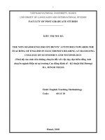
The figure above shows a physical view of a Virtex®-4 FPGA. To a signal DSP engineer, an
FPGA can be thought of as a 2-D array of logic slices striped with columns of hard macro
blocks (block memory and arithmetic blocks) suitable for implementing DSP functions,
embedded within a configurable interconnect mesh. In a Virtex®-4 FPGA, the DSP blocks
(shown in the next figure) can run in excess of 450 MHz, and are pitch-matched to dual
port memory blocks (BRAMs) whose ports can be configured to a wide range of word sizes
(18 Kb total per BRAM). The Virtex®-4 SX55 device contains 512 such DSP blocks and
BRAMs. In System Generator, you can access all of these resources through arithmetic and
logic abstractions to build very high performance digital filters, FFTs, and other arithmetic
and signal processing functions.
While the multiply-accumulate function supported by a Virtex®-4 DSP block is familiar to
a DSP engineer, it is instructive to take a closer look at the Virtex® FPGA family logic slice
(shown below), which is the fundamental unit of the logic fabric array.
Each logic slice contains two 4-input lookup tables (LUTs), two configurable D-flip flops,
multiplexers, dedicated carry logic, and gates used for creating slice-based multipliers.
Each LUT can implement an arbitrary 4-input Boolean function. Coupled with dedicated
logic for implementing fast carry circuits, the LUTs can also be used to build fast
adder/subtractors and multipliers of essentially any word size. In addition to
implementing Boolean functions, each LUT can also be configured as a 16x1 bit RAM or as
12
www.xilinx.com
System Generator for DSP User Guide
UG639 (v 13.4) January 18, 2012
A Brief Introduction to FPGAs
a shift register (SRL16). An SRL16 shift register is a synchronously clocked 16x1 bit delay
line with a dynamically addressable tap point.
In System Generator, these different memory options are represented with higher-level
abstractions. Instead of providing a D-flip flop primitive, System Generator provides a
register of arbitrary size. There are two blocks that provide abstractions of arbitrary
width, arbitrary depth delay lines that map directly onto the SRL16 configuration. The
delay block can be used for pipeline balancing, and can also be used as storage for timedivision multiplexed (TDM) data streams. The addressable shift register (ASR) block,
with a function depicted in the figure below, provides an arbitrary width, arbitrary depth
tapped delay line. This block is of particular interest to the DSP engineer, since it can be
used to implement tapped delay lines as well as sweeping through TDM data streams.
Although random access memories can be constructed either out of the BRAM or LUT
(RAM16x1) primitives, doing so can require considerable care to ensure most efficient
mappings, and considerable clerical attention to detail to correctly assemble the primitives
into larger structures. System Generator removes the need for such tasks.
For example, the dual port RAM (DPRAM) block shown in the figure below maps
efficiently onto as many BRAM or RAM16x1 components on the device as are necessary to
implement the desired memory. As can be seen from the mask dialog box for the DPRAM,
the interface allows you to specify a type of memory (BRAM or RAM16x1), depth (data
System Generator for DSP User Guide
UG639 (v 13.4) January 18, 2012
www.xilinx.com
13
Chapter 1: Hardware Design Using System Generator
width is inferred from the Simulink signal driving a particular input port), initial memory
contents, and other characteristics.
In general, System Generator maps abstractions onto device primitives efficiently, freeing
you from worrying about interconnections between the primitives. System Generator
employs libraries of intellectual property (IP) when appropriate to provide efficient
implementations of functions in the block libraries. In this way, you don’t always have to
have detailed knowledge of the underlying FPGA details. However, when it makes sense
to implement an algorithm using basic functions (e.g., adder, register, memory), System
Generator allows you to exploit your FPGA knowledge while reducing the clerical tasks of
managing all signals explicitly.
System Generator library blocks and the mapping from Simulink to hardware are
described in detail in subsequent topics of this documentation. There is a wealth of
detailed information about FPGAs that can be found online at ,
including data books, application notes, white papers, and technical articles.
Note to the DSP Engineer
System Generator extends Simulink to enable hardware design, providing high-level
abstractions that can be automatically compiled into an FPGA. Although the arithmetic
abstractions are suitable to Simulink (discrete time and space dynamical system
simulation), System Generator also provides access to features in the underlying FPGA.
The more you know about a hardware realization (e.g., how to exploit parallelism and
pipelining), the better the implementation you’ll obtain. Using IP cores makes it possible to
have efficient FPGA designs that include complex functions like FFTs. System Generator
also makes it possible to refine a model to more accurately fit the application.
Scattered throughout the System Generator documentation are notes that explain ways in
which system parameters can be used to exploit hardware capabilities.
14
www.xilinx.com
System Generator for DSP User Guide
UG639 (v 13.4) January 18, 2012
Design Flows using System Generator
Note to the Hardware Engineer
System Generator does not replace hardware description language (HDL)-based design,
but does makes it possible to focus your attention only on the critical parts. By analogy,
most DSP programmers do not program exclusively in assembler; they start in a higherlevel language like C, and write assembly code only where it is required to meet
performance requirements.
A good rule of thumb is this: in the parts of the design where you must manage internal
hardware clocks (e.g., using the DDR or phased clocking), you should implement using
HDL. The less critical portions of the design can be implemented in System Generator, and
then the HDL and System Generator portions can be connected. Usually, most portions of
a signal processing system do not need this level of control, except at external interfaces.
System Generator provides mechanisms to import HDL code into a design (see Importing
HDL Modules) that are of particular interest to the HDL designer.
Another aspect of System Generator that is of interest to the engineer who designs using
HDL is its ability to automatically generate an HDL testbench, including test vectors. This
aspect is described in the topic HDL Testbench.
Finally, the hardware co-simulation interfaces described in the topic Using Hardware CoSimulation allow you to run a design in hardware under the control of Simulink, bringing
the full power of MATLAB and Simulink to bear for data analysis and visualization.
Design Flows using System Generator
System Generator can be useful in many settings. Sometimes you may want to explore an
algorithm without translating the design into hardware. Other times you might plan to use
a System Generator design as part of something bigger. A third possibility is that a System
Generator design is complete in its own right, and is to be used in FPGA hardware. This
topic describes all three possibilities.
Algorithm Exploration
System Generator is particularly useful for algorithm exploration, design prototyping, and
model analysis. When these are the goals, you can use the tool to flesh out an algorithm in
order to get a feel for the design problems that are likely to be faced, and perhaps to
estimate the cost and performance of an implementation in hardware. The work is
preparatory, and there is little need to translate the design into hardware.
In this setting, you assemble key portions of the design without worrying about fine points
or detailed implementation. Simulink blocks and MATLAB M-code provide stimuli for
simulations, and for analyzing results. Resource estimation gives a rough idea of the cost
of the design in hardware. Experiments using hardware generation can suggest the
hardware speeds that are possible.
Once a promising approach has been identified, the design can be fleshed out. System
Generator allows refinements to be done in steps, so some portions of the design can be
made ready for implementation in hardware, while others remain high-level and abstract.
System Generator's facilities for hardware co-simulation are particularly useful when
portions of a design are being refined.
Implementing Part of a Larger Design
Often System Generator is used to implement a portion of a larger design. For example,
System Generator is a good setting in which to implement data paths and control, but is
System Generator for DSP User Guide
UG639 (v 13.4) January 18, 2012
www.xilinx.com
15
Chapter 1: Hardware Design Using System Generator
less well suited for sophisticated external interfaces that have strict timing requirements. In
this case, it may be useful to implement parts of the design using System Generator,
implement other parts outside, and then combine the parts into a working whole.
A typical approach to this flow is to create an HDL wrapper that represents the entire
design, and to use the System Generator portion as a component. The non-System
Generator portions of the design can also be components in the wrapper, or can be
instantiated directly in the wrapper.
Implementing a Complete Design
Many times, everything needed for a design is available inside System Generator. For such
a design, pressing the Generate button instructs System Generator to translate the design
into HDL, and to write the files needed to process the HDL using downstream tools. The
files written include the following:
•
HDL that implements the design itself;
•
A clock wrapper that encloses the design. This clock wrapper produces the clock and
clock enable signals that the design needs.
•
A HDL testbench that encloses the clock wrapper. The testbench allows results from
Simulink simulations to be compared against ones produced by a logic simulator.
•
Project files and scripts that allow various synthesis tools, such as XST and Synplify
Pro to operate on System Generator HDL
•
Files that allow the System Generator HDL to be used as a project in Project
Navigator.
For details concerning the files that System Generator writes, see the topic Compilation
Results.
16
www.xilinx.com
System Generator for DSP User Guide
UG639 (v 13.4) January 18, 2012
System-Level Modeling in System Generator
System-Level Modeling in System Generator
System Generator allows device-specific hardware designs to be constructed directly in a
flexible high-level system modeling environment. In a System Generator design, signals
are not just bits. They can be signed and unsigned fixed-point numbers, and changes to the
design automatically translate into appropriate changes in signal types. Blocks are not just
stand-ins for hardware. They respond to their surroundings, automatically adjusting the
results they produce and the hardware they become.
System Generator allows designs to be composed from a variety of ingredients. Data flow
models, traditional hardware design languages (VHDL, Verilog, and EDIF), and functions
derived from the MATLAB programming language, can be used side-by-side, simulated
together, and synthesized into working hardware. System Generator simulation results are
bit and cycle-accurate. This means results seen in simulation exactly match the results that
are seen in hardware. System Generator simulations are considerably faster than those
from traditional HDL simulators, and results are easier to analyze.
System Generator Blocksets
Describes how System Generator's blocks are
organized in libraries, and how the blocks can be
parameterized and used.
Signal Types
Describes the data types used by System Generator
and ways in which data types can be automatically
assigned by the tool.
Bit-True and Cycle-True
Modeling
Specifies the relationship between the Simulink-based
simulation of a System Generator model and the
behavior of the hardware that can be generated from
it.
Timing and Clocking
Describes how clocks are implemented in hardware,
and how their implementation is controlled inside
System Generator. Explains how System Generator
translates a multirate Simulink model into working
clock-synchronous hardware.
Synchronization Mechanisms
Describes mechanisms that can be used to
synchronize data flow across the data path elements
in a high-level System Generator design, and
describes how control path functions can be
implemented.
Block Masks and Parameter
Passing
Explains how parameterized systems and subsystems
are created in Simulink.
Resource Estimation
Describes how to generate estimates of the hardware
needed to implement a System Generator design.
System Generator for DSP User Guide
UG639 (v 13.4) January 18, 2012
www.xilinx.com
17
Chapter 1: Hardware Design Using System Generator
System Generator Blocksets
A Simulink blockset is a library of blocks that can be connected in the Simulink block editor
to create functional models of a dynamical system. For system modeling, System
Generator blocksets are used like other Simulink blocksets. The blocks provide
abstractions of mathematical, logic, memory, and DSP functions that can be used to build
sophisticated signal processing (and other) systems. There are also blocks that provide
interfaces to other software tools (e.g., FDATool, ModelSim) as well as the System
Generator code generation software.
System Generator blocks are bit-accurate and cycle-accurate. Bit-accurate blocks produce
values in Simulink that match corresponding values produced in hardware; cycle-accurate
blocks produce corresponding values at corresponding times.
18
www.xilinx.com
System Generator for DSP User Guide
UG639 (v 13.4) January 18, 2012
System-Level Modeling in System Generator
Xilinx Blockset
The Xilinx Blockset is a family of libraries that contain basic System Generator blocks.
Some blocks are low-level, providing access to device-specific hardware. Others are highlevel, implementing (for example) signal processing and advanced communications
algorithms. For convenience, blocks with broad applicability (e.g., the Gateway I/O
blocks) are members of several libraries. Every block is contained in the Index library. The
libraries are described below.
Library
Description
AXI4
Blocks with interfaces that conform to the AXI™4 specification
Basic Elements
ElementsStandard building blocks for digital logic
Communication
Forward error correction and modulator blocks, commonly used in
digital communications systems
Control Logic
Blocks for control circuitry and state machines
DSP
Digital signal processing (DSP) blocks
Data Types
Blocks that convert data types (includes gateways)
Floating-Point
Blocks that support the Floating-Point data type
Index
Every block in the Xilinx Blockset.
Math
Blocks that implement mathematical functions
Memory
Blocks that implement and access memories
Shared Memory
Blocks that implement and access Xilinx shared memories
Tools
“Utility” blocks, e.g., code generation (System Generator token),
resource estimation, HDL co-simulation, etc
Note: More information concerning blocks can be found in the topic Xilinx Blockset.
Xilinx Reference Blockset
The Xilinx Reference Blockset contains composite System Generator blocks that implement
a wide range of functions. Blocks in this blockset are organized by function into different
libraries. The libraries are described below.
Library
Description
Communication
Blocks commonly used in digital communications systems
Control Logic
LogicBlocks used for control circuitry and state machines
DSP
Digital signal processing (DSP) blocks
Imaging
Image processing blocks
Math
Blocks that implement mathematical functions
Each block in this blockset is a composite, i.e., is implemented as a masked subsystem, with
parameters that configure the block.
System Generator for DSP User Guide
UG639 (v 13.4) January 18, 2012
www.xilinx.com
19
Chapter 1: Hardware Design Using System Generator
You can use blocks from the Reference Blockset libraries as is, or as starting points when
constructing designs that have similar characteristics. Each reference block has a
description of its implementation and hardware resource requirements. Individual
documentation for each block is also provided in the topic Xilinx Reference Blockset.
Signal Types
In order to provide bit-accurate simulation of hardware, System Generator blocks operate
on Boolean, floating-point, and arbitrary precision fixed-point values. By contrast, the
fundamental scalar signal type in Simulink is double precision floating point. The
connection between Xilinx blocks and non-Xilinx blocks is provided by gateway blocks. The
gateway in converts a double precision signal into a Xilinx signal, and the gateway out
converts a Xilinx signal into double precision. Simulink continuous time signals must be
sampled by the Gateway In block.
Most Xilinx blocks are polymorphic, i.e., they are able to deduce appropriate output types
based on their input types. When full precision is specified for a block in its parameters
dialog box, System Generator chooses the output type to ensure no precision is lost. Sign
extension and zero padding occur automatically as necessary. User-specified precision is
usually also available. This allows you to set the output type for a block and to specify how
quantization and overflow should be handled. Quantization possibilities include unbiased
rounding towards plus or minus infinity, depending on sign, or truncation. Overflow
options include saturation, truncation, and reporting overflow as an error.
Note: System Generator data types can be displayed by selecting Format > Port Data Types in
Simulink. Displaying data types makes it easy to determine precision throughout a model. If, for
example, the type for a port is Fix_11_9, then the signal is a two's complement signed 11-bit number
20
www.xilinx.com
System Generator for DSP User Guide
UG639 (v 13.4) January 18, 2012
System-Level Modeling in System Generator
having nine fractional bits. Similarly, if the type is Ufix_5_3, then the signal is an unsigned 5-bit
number having three fractional bits.
In the System Generator portion of a Simulink model, every signal must be sampled.
Sample times may be inherited using Simulink's propagation rules, or set explicitly in a
block customization dialog box. When there are feedback loops, System Generator is
sometimes unable to deduce sample periods and/or signal types, in which case the tool
issues an error message. Assert blocks must be inserted into loops to address this problem.
It is not necessary to add assert blocks at every point in a loop; usually it suffices to add an
assert block at one point to “break” the loop.
Note: Simulink can display a model by shading blocks and signals that run at different rates with
different colors (Format > Sample Time Colors in the Simulink pulldown menus). This is often useful
in understanding multirate designs.
Floating-Point Data Type
System Generator blocks found in the Floating-Point library support the floating-point
data type.
System Generator uses the Floating-Point Operator v6.0 IP core to leverage the
implementation of operations such as addition/subtraction, multiplication, comparisons
and data type conversion.
The floating-point data type support is in compliance with IEEE-754 Standard for FloatingPoint Arithmetic. Single precision, Double precision and Custom precision floating-point
data types are supported for design input, data type display and for data rate and type
propagation (RTP) across the supported System Generator blocks.
IEEE-754 Standard for Floating-Point Data Type
As shown below, floating-point data is represented using one Sign bit (S), X exponent bits
and Y fraction bits. The Sign bit is always the most-significant bit (MSB).
S
X Exponent bits
E0 to Ex-1
Y Fraction Bits
F0 to FY-1
According to the IEEE-754 standard, a floating-point value is represented and stored in the
normalized form. In the normalized form the exponent value E is a biased/normalized
value. The normalized exponent, E, equals the sum of the actual exponent value and the
exponent bias. In the normalized form, Y-1 bits are used to store the fraction value. The F 0
fraction bit is always a hidden bit and its value is assumed to be 1.
S represents the value of the sign of the number. If S is 0 then the value is a positive
floating-point number; otherwise it is negative. The X bits that follow are used to store the
normalized exponent value E and the last Y-1 bits are used to store the fraction/mantissa
value in the normalized form.
For the given exponent width, the exponent bias is calculated using the following
equation:
Exponent_bias = 2(X - 1) - 1, where X is the exponent bit width.
System Generator for DSP User Guide
UG639 (v 13.4) January 18, 2012
www.xilinx.com
21
Chapter 1: Hardware Design Using System Generator
According to the IEEE standard, a single precision floating-point data is represented using
32 bits. The normalized exponent and fraction/mantissa are allocated 8 and 24 bits,
respectively. The exponent bias for single precision is 127. Similarly, a double precision
floating-point data is represented using a total of 64 bits where the exponent bit width is 11
and the fraction bit width is 53. The exponent bias value for double precision is 1023.
The normalized floating-point number in the equation form is represented as follows:
Normalized Floating-Point Value = (-1)S x F0.F1F2 …. FY-2FY-1 x (2)E
The actual value of exponent (E_actual) = E - Exponent_bias. Considering 1 as the value for
the hidden bit F0 and the E_actual value, a floating-point number can be calculated as
follows:
FP_Value = (-1)S x 1.F1F2 …. FY-2FY-1 x (2)(E_actual)
Floating-Point Data Representation in System Generator
The System Generator Gateway In block previously only supported the Boolean and
Fixed-point data types. As shown below, the Gateway In block GUI and underlying mask
parameters now support the Floating-point data type as well. You can select either a
Single, Double or Custom precision type after specifying the floating-point data type.
For example, if Exponent width of 9 and Fraction width of 31 is specified then the floatingpoint data value will be stored in total 40 bits where the MSB bit will be used for sign
representation, the following 9 bits will be used to store biased exponent value and the 30
LSB bits will be used to store the fractional value.
In compliance with the IEEE-754 standard, if Single precision is selected then the total bit
width is assumed to be 32; 8 bits for the exponent and 24 bits for the fraction. Similarly
when Double precision is selected, the total bit width is assumed to be 64 bits; 11 bits for
the exponent and 53 bits for the fraction part. When Custom precision is selected, the
Exponent width and Fraction width fields are activated and you are free to specify values
for these fields (8 and 24 are the default values). The total bit width for Custom precision
data is the summation of the number of exponent bits and the number of fraction bits.
22
www.xilinx.com
System Generator for DSP User Guide
UG639 (v 13.4) January 18, 2012
System-Level Modeling in System Generator
Similar to fraction bit width for Single precision and Double precision data types the
fraction bit width for Custom precision data type must include the hidden bit F0
Displaying the Data Type on Output Signals
As shown below, after a successful rate and type propagation, the floating-point data type
is displayed on the output of each System Generator block.To display the signal data type
as shown in the diagram below, you select the pulldown menu item Format > Port/Signal
Displays > Port Data Types.
A floating-point data type is displayed using the format:
XFloat_<exponent_bit_width>_<fraction_bit_width>. Single and Double
precision data types are displayed using the string “XFloat_8_24” and “XFloat_11_53”,
respectively.
If for a Custom precision data type the exponent bit width 9 and the fraction bit width 31
are specified, then it will be displayed as “XFloat_9_31”. A total of 40 bits will be used to
store the floating-point data value. Since floating-point data is stored in a normalized form,
the fractional value will be stored in 30 bits.
In System Generator the fixed-point data type is displayed using format
XFix_<total_data_width>_<binary_point_width>. For example, a fixed-point
data type with the data width of 40 and binary point width of 31 is displayed as
XFix_40_31.
It is necessary to point out that in the fixed-point data type the actual number of bits used
to store the fractional value is different from that used for floating-point data type. In the
example above, all 31 bits are used to store the fractional bits of the fixed-point data type.
System Generator uses the exponent bit width and the fraction bit width to configure and
generate an instance of the Floating-Point Operator core.
System Generator for DSP User Guide
UG639 (v 13.4) January 18, 2012
www.xilinx.com
23
Chapter 1: Hardware Design Using System Generator
Rate and Type Propagation
During data rate and type propagation across a System Generator block that supports
floating-point data, the following design rules are verified. The appropriate error is issued
if one of the following violations is detected.
1.
If a signal carrying floating-point data is connected to the port of a System Generator
block that doesn’t support the floating-point data type.
2.
If the data input (both A and B data inputs, where applicable) and the data output of a
System Generator block are not of the same floating-point data type. The DRC check
will be made between the two inputs of a block as well as between an input and an
output of the block.
If a Custom precision floating-point data type is specified, the exponent bit width and
the fraction bit width of the two ports are compared to determine that they are of the
same data type.
Note: The Convert and Relational blocks are excluded from this check. The Convert block
supports Float-to-float data type conversion between two different floating-point data types. The
Relational block output is always the Boolean data type because it gives a true or false result for
a comparison operation.
3.
If the data inputs are of the fixed-point data type and the data output is expected to be
floating-point and vice versa.
Note: The Convert and Relational blocks are excluded from this check. The Convert block
supports Fixed-to-float as well as Float-to-fixed data type conversion. The Relational block
output is always the Boolean data type because it gives a true or false result for a comparison
operation.
4.
If User Defined precision is selected for the Output Type of blocks that support the
floating-point data type. For example, for blocks such as AddSub, Mult, CMult, and
MUX, only Full output precision is supported if the data inputs are of the floatingpoint data type.
5.
If the Carry In port or Carry Out port is used for the AddSub block when the operation
on a floating-point data type is specified.
6.
If the Floating-Point Operator IP core gives an error for DRC rules defined for the IP.
AXI Signal Groups
System Generator blocks found in the AXI4 library contain interfaces that conform to the
AXI™ 4 specification. Blocks with AXI interfaces are drawn such that ports relating to a
particular AXI interface are grouped and colored in similarly. This makes it easier to
identify data and control signals pertaining to the same interface. Grouping similar AXI
ports together also make it possible to use the Simulink Bus Creator and Simulink Bus
Selector blocks to connect groups of signals together. More information on AXI can be
found in the section entitled AXI Interface. For more detailed information on the AMBA
AXI4 specification, please refer to the Xilinx AMBA AXI4 documents found at the
following location: />
Bit-True and Cycle-True Modeling
Simulations in System Generator are bit-true and cycle-true. To say a simulation is bit-true
means that at the boundaries (i.e., interfaces between System Generator blocks and nonSystem Generator blocks), a value produced in simulation is bit-for-bit identical to the
corresponding value produced in hardware. To say a simulation is cycle-true means that at
the boundaries, corresponding values are produced at corresponding times. The
24
www.xilinx.com
System Generator for DSP User Guide
UG639 (v 13.4) January 18, 2012
System-Level Modeling in System Generator
boundaries of the design are the points at which System Generator gateway blocks exist.
When a design is translated into hardware, Gateway In (respectively, Gateway Out) blocks
become top-level input (resp., output) ports.
Timing and Clocking
Discrete Time Systems
Designs in System Generator are discrete time systems. In other words, the signals and the
blocks that produce them have associated sample rates. A block’s sample rate determines
how often the block is awoken (allowing its state to be updated). System Generator sets
most sample rates automatically. A few blocks, however, set sample rates explicitly or
implicitly.
Note: For an in-depth explanation of Simulink discrete time systems and sample times, consult the
Using Simulink reference manual from the MathWorks, Inc.
A simple System Generator model illustrates the behavior of discrete time systems.
Consider the model shown below. It contains a gateway that is driven by a Simulink source
(Sine Wave), and a second gateway that drives a Simulink sink (Scope).
The Gateway In block is configured with a sample period of one second. The Gateway Out
block converts the Xilinx fixed-point signal back to a double (so it can analyzed in the
Simulink scope), but does not alter sample rates. The scope output below shows the
unaltered and sampled versions of the sine wave.
Multirate Models
System Generator supports multirate designs, i.e., designs having signals running at
several sample rates. System Generator automatically compiles multirate models into
System Generator for DSP User Guide
UG639 (v 13.4) January 18, 2012
www.xilinx.com
25