Development and realization of a distributed control algorithm for an inverted rotary pendulum using freeRTOS with TTCAN communication
Bạn đang xem bản rút gọn của tài liệu. Xem và tải ngay bản đầy đủ của tài liệu tại đây (3.95 MB, 103 trang )
UNIVERSITÄT
SIEGEN
Institut für Embedded Systems
Master Thesis
Development and Realization of
a distributed control algorithm for an inverted rotary pendulum
using FreeRTOS with TTCAN communication
Submitted by:
Bui, Hoang Dung
Matr.-Nr.: 976477
Supervised by:
Prof. Dr. Roman Obermaisser
Dr.-Ing. Walter Lang
04.2014
Master Thesis’s Report
Development and Realization of
a distributed control algorithm for an inverted rotary pendulum
using FreeRTOS with TTCAN communication
i
Table Content
1 Introduction......................................................................................................................................................1
1.1Overview ....................................................................................................................................................1
1.2 Master thesis objectives ............................................................................................................................2
1.3 Report’s structure .....................................................................................................................................3
2 Basic concepts and Related Works...................................................................................................................5
2.1 Related Work .............................................................................................................................................5
2.1.1 The mechanical design .......................................................................................................................5
2.1.2 The results from the student work.....................................................................................................7
2.2 Embedded C ..............................................................................................................................................9
2.2.1 Basic concepts in Embedded C ........................................................................................................ 10
2.2.2 Control Statements ......................................................................................................................... 11
2.2.3 Pointer, Arrays and Structures ........................................................................................................ 13
2.3 FreeRTOS ................................................................................................................................................ 14
2.3.1 Introduction..................................................................................................................................... 14
2.3.2 Used FreeRTOS Library Classes ....................................................................................................... 18
2.4 CAN and Time Trigger CAN ..................................................................................................................... 20
2.4.1 Controller Area Network – CAN ...................................................................................................... 21
2.4.2 Time Trigger CAN – TTCAN .............................................................................................................. 22
2.5 AT90CAN128 Microcontroller ................................................................................................................ 26
2.5.1 The specific knowledge about AT90CAN128................................................................................... 26
2.5.2 CAN Controller in AT90CAN128 ...................................................................................................... 28
3 Modeling and Microcontroller’s Structures .................................................................................................. 33
3.1 The nonlinear IRP Model ........................................................................................................................ 33
3.2 Microcontroller Structures ..................................................................................................................... 37
3.2.1 TTCAN Scheduler ............................................................................................................................. 38
3.2.2 Time Trigger Matrices...................................................................................................................... 40
3.2.3 TTCAN_Scheduler Task and CAN ISR ............................................................................................... 43
3.2.4 Microcontroller Tasks ...................................................................................................................... 45
4 Implementation ............................................................................................................................................. 52
4.1 Nonlinear IRP model............................................................................................................................... 52
4.2 The common parts ................................................................................................................................. 54
ii
4.2.1 CAN Tasks ........................................................................................................................................ 54
4.2.2 CAN ISR ............................................................................................................................................ 59
4.3 SEN-uC .................................................................................................................................................... 61
4.3.1 Specific External Interrupt Service Routines .................................................................................. 61
4.3.2 Data_Preparation() Task.................................................................................................................. 62
4.4 LCD-uC .................................................................................................................................................... 63
Data_Reception() Task ........................................................................................................................ 63
LCD_Display() Task............................................................................................................................... 64
4.5 PUSB-uC .................................................................................................................................................. 65
PWM_Calculation() Task ..................................................................................................................... 65
PushedButton_Detection() Task.......................................................................................................... 67
4.6 MOTO-uC ................................................................................................................................................ 68
4.6.1 Timer/Counter 3 Compare Match Interrupts ................................................................................... 69
4.6.2 DC-motor Control Tasks ................................................................................................................. 70
4.7 Parameters Estimation ........................................................................................................................... 74
4.7.1 The IRP parameters ......................................................................................................................... 74
4.7.2 LQR parameters ............................................................................................................................... 76
4.7.3 PWM and Sampling frequencies ..................................................................................................... 77
5 Results and Discussion .................................................................................................................................. 78
5.1 Results .................................................................................................................................................... 78
5.1.1 The nonlinear IRP model behavior .................................................................................................. 78
5.1.2 The IRP machine Operation............................................................................................................. 80
5.2 Discussion ............................................................................................................................................... 86
5.2.1 Sampling and PWM frequency ........................................................................................................ 86
5.2.2 Mechanical Structures ..................................................................................................................... 87
6 Conclusion ..................................................................................................................................................... 88
Reference ......................................................................................................................................................... 89
Bibliography...................................................................................................................................................... 89
Appendix........................................................................................................................................................... 90
iii
Chapter 1 Introduction
1 Introduction
The Inverted Rotary Pendulum - IRP is a machine which is invented in 1992 by Katsuhisa Furuta. It contains
a driven arm and a pendulum which is attached on the arm. Both the arm and pendulum can rotate freely in
the horizontal and vertical plane respectively. In order to control the IRP, it is needed the cooperation of
several different fields such as mechanics, control theory and microcontroller science. From the mechanical
field, the IRP is a machine which transmits the energy by an input – the DC-motor to control two rotations. In
the control system theory’s view, the IRP is nonlinear system and only two states can be measured directly.
From the microcontroller science side, microcontrollers should be fast enough to produce appropriate actions
to response any variation of the IRP. The IRP is considered to work well if its pendulum can stays at upright
position forever. Therefore this project’s goal is step by step to find a solution which makes the IRP operating
well in the specific requirements. In this chapter would give an overview idea about the real IRP machine, the
master thesis goal in detail and the report’s structure.
1.1Overview
This master thesis project is the step to go further from the student work “Modeling and Simulation of an
Inverted Rotary Pendulum” [Bui, 2013]. In the student work, the approximate linear model of the IRP had
built. Moreover, the control theory which controls IRP had also established, it was State Space method. That
method was applied to the Simulink model then the model’s response was stable and worked at upright
position. However, there are differences between the model and the machine. That is the built model was
linear model whereas the machine contains nonlinear parts. That issue would be solved in this thesis.
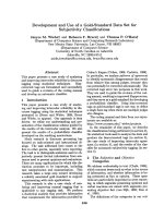
Moreover, this project would go deeper to the control problem of the machine. The IRP machine is shown on
the figure 1.1
Figure 1.1 the IRP Overview
1
Chapter 1 Introduction
On the figure 1.1, the main parts of the IRP can be seen: the pendulum/mass M, the gearbox and DC-motor,
belt transmission, the Frame, tow sensor and the foundation. The IRP movement begins from the DC-motor.
The movement is transferred to the Frame via the gearbox and belt transmission. When the Frame rotates, it
makes the mass/pendulum swinging up to the upright position. The two movements which are measured by
two encoders are the angle positions of the Frame and the mass M. The two measured angles are called Arm
angle and Pendulum angle respectively.
Signals from both encoders which are primitive processed by circuit 1 are sent to the integrated circuit 2. The
integrated circuit 2 is a compound circuit board which consists of four microcontrollers AT90CAN128 and
several equipment such as a LCD DOGS102-6, pushed button matrix, LEDs, signal ports, fours PCA82C250,
L6205D. The four microcontrollers process the data which are used to control DC-motor. The pushed button
matrix and LCD DOGS102 are used to communicate with users (Human Machine Interface – HMI). The
LCD shows the information of the IRP system. The button matrix receives the commands from users then
manipulates the state of the IRP system. Four PCA82C250s are the bridge between the CAN controller and
the CAN Bus. The L6205D receives the signal PWM from I/O port of microcontroller and add more energy
to control DC-motor directly.
There are four microcontrollers used to control the IRP. The first microcontroller detects the movements of
Arm angle and Pendulum angle and transmits the new angles to other microcontroller. The second
microcontroller displays all the IRP information on the LCD. The third one receives signal from the button
matrix and control the IRP working or stopping. The last microcontroller controls the rotation of DC motor,
thereby control the IRP movement.
1.2 Master thesis objectives
As mentioned earlier, this thesis is completed the work-in-progress from the student work. The basic and
critical duty is to write the codes for four microcontrollers to control the IRP machine working at upright
position and is stable there. In order to implement that duty, some minimum objectives should be fulfilled.
They are:
-
Build nonlinear model of IRP.
-
Define constraint times which can keep the system working stable.
-
Handle with the sensor signal and the backlash.
-
Check capacity of Microcontrollers to meet the IRP control requirements.
2
Chapter 1 Introduction
-
Write the program to control the IRP working at upright position with the stability time about 5
seconds.
As the basic objectives are completed, the master thesis goals are extended. There are some extra parts which
would be added to the system to make it friendly to human. The additional objectives are:
-
Establish two separate programs to control IRP in two phases: Swing up phase and Upright phase.
-
Human – Machine Interface (HMI): show IRP information on LCD, and some buttons to control IRP
-
Be able to change the reference input of arm angle.
-
Be able to transmit the signal of IRP angles to computer, and shown it graphically.
That is the objectives of this master thesis project. Subsequently, the report structure would be introduced.
1.3 Report’s structure
The report included six chapters. Chapter sequence was formed to assist reader in understanding step by step
how the student’s work was implemented. Knowledge was presented in appropriate chapters and described
how they can be applied to this specific IRP.
Chapter 1 presents general knowledge about IRP, objectives and report’s structure.
Chapter 2 describes the related works and basic concepts which would be used to control the IRP machine.
Chapter 3 introduces the designed work on each microcontroller. It starts with the general structures in the
four microcontroller such as the Scheduler, the CAN message, TTCAN_Scheduler task and CAN ISR. Then
it works with the specific tasks which are for the specific microcontrollers.
Chapter 4 would implement the design in the programming language. In this chapter, the description of the
microcontroller structures are converted to the Embedded C, FreeRTOS code and they will actually control
the IRP machine. It also describes the parameter estimation process.
Chapter 5 would present the results from chapter 4. The response in the nonlinear model and the IRP machine
will be shown and discussed. The learned knowledge is also discussed here.
Chapter 6 concludes about the master thesis project. The achieved goals were reached in this work.
In the end of the work, the declaration, reference and appendix – the program codes in detail of the former
chapters are presented.
3
Chapter 1 Introduction
The aforesaid information plays as a key role to assist readers in having an overview of this master thesis.
The second chapter hereafter presents some basic concepts and related works regarding the IRP.
4
Chapter 2 Basic Concepts and Related Works
2 Basic concepts and Related Works
This chapter presents the knowledge which is the foundation to develop the IRP operation. The first section
of chapter would recall the related works, which are already completed and their results will be applied in this
master thesis. The second section presents the basic concepts which are deployed to program the IRP control
code such as Embedded C, FreeRTOS, TTCAN and AT90CAN128 microcontroller. Because of the
enormous knowledge of those fields, only the specific knowledge will be introduced.
2.1 Related Work
In order to carry out the controlled works of IRP machine in upright position, that is obviously essential to
have a foundation. The first foundation is the existence of a real IRP machine, which is outlined the first
chapter. The technical parameters, the engineering drawings would be described in detail in the section 2.1.1.
The second foundation is the control theory, which is responsible to keep the mass of IRP machine at upright
position. That theory was established in my student work [Bui, 2013], and was applied in the IRP model. The
response of that model was satisfied the control requirements in the response time and the stable. The key
points of both foundations would be the following sections.
2.1.1 The mechanical design
This section presents the engineering draws of IRP machine’s structure. The overview of the IRP in design
phase is shown in the figure below.
Figure 2.1: The 3-D draw of the IRP
5
Chapter 2 Basic Concepts and Related Works
In this draws the blue item represent for the DC-motor. The belt transmission and the bearing are missing.
From the 3-D view, it is projected in the front and top direction. The results are the top view and front view
draws with more detail about the IRP. From the front view of the IRP, its height is 400 mm, the length is 350
mm and the width is 200 mm.
Figure 2.2 Front view of the IRP
Figure 2.3 Top view of the IRP
The front view and the top view give the image of dimension of the IRP, the distance among components. It
also gives a visual view of the mechanical structure about the machine. Based on the dimension, the
procurement of the components such as DC-motor, gearbox, belt transmission can perform to meet the
requirements. The engineering draws then are sent to the mechanical shop, which is charge of the production
and assembly the foundation and other components.
6
Chapter 2 Basic Concepts and Related Works
2.1.2 The results from the student work
The works which were accomplished in the student work would be recalled in this section. In the student
work, the linear IRP model was built. Moreover, the adequate control theory was also found that was State
Space Control method. In this method, the system equations were set to become the equation system of the
first order. The system states and inputs were set to be respective vectors. The key point of state space
method is in order to keep the system in steady state, the system states must go to zero as the time run to
infinity. It is obvious that the opened IRP was impossible to hold itself at the upright position. To hold the
IRP at the desired position, a feedback part which was also called the controller was added to the IRP. This
part did nothing else than measure the output, multiplied with the feedback parameters then transmitted the
result to compare with the reference input. If there is a difference between the reference input and the output,
the difference will be converted to voltage signal and control the DC-motor to run to the desired position. If
the difference is zero, the IRP do nothing. The listed figures below shows the Simulink model of the IRP.
Figure 2.4 Plant with feedback signal
In the figure above describes the IRP model without the reference input or can say the reference input is zero.
There are four states in the system. The states are collected by the Feedback component then the feedback
signal is sent back to the PLANT to adjust the DC-motor movement. The structure of the PLANT and
Feedback component is shown on the figure below.
7
Chapter 2 Basic Concepts and Related Works
Figure 2.5: Plant Part
Figure 2.6: Feedback component
As explained, the feedback part is the key part to keep IRP working properly. In other work, the feedback
parameters are the critical things of the system. There are some ways to calculate those parameters. However,
in the student work the parameter was calculated by linear quadratic regulator (LQR) method, which was able
to balance between the system effort and the output response. Specifically, the parameters were processed by
function lqr() in the Matlab software.
The formula to calculate the feedback signal is:
Feedback K1* Arm _ Position K 2 * Pendulum_ Position K 3 * Arm _ Velovity K 4 * Pendulum_ Velocity
8
Chapter 2 Basic Concepts and Related Works
And the controlled signal is equal to Feedback signal but with opposite sign:
Controlled _ Signal Feedback
In order to extend the IRP capability, an integral component was added beside the feedback part. With this
additional part, the IRP is able to work at arbitrary position of the arm (in working range) and the mass is still
hold at the upright position.
Figure 2.7: The full IRP model
The new component produces an added signal by formula:
Added _ Signal ( Arm _ Position Cons tan t ) * dt * Ki
Where dt is the time period between to two times taken the sensor signal which is equal to 3 milliseconds.
In this content, the controlled signal is different to the feedback signal, and the controlled signal is calculated
by the formula:
Controlled _ Signal Added _ Signal Feedback
In addition, the moment of inertia of IRP was calculated, and would be used in this master thesis work.
2.2 Embedded C
Embedded C is branch of C programming language which is developed to apply to embedded microcontroller
application. The main difference between the C language and Embedded C is what are they designed for. The
first language is designated for personal computers which have an operating system. When a program was
9
Chapter 2 Basic Concepts and Related Works
executed on the computer, it returns to the operating system. Meanwhile, the second one is designed to work
on microcontrollers which have no operating system thereby it is not allowed fall out of the program any
time. Hence every embedded system microcontroller applications have an infinite loop into it [Barnett et.al,
2003].
In an embedded C program, functions are formed by sets of basic instructions and treated as higher-level
operations, which are then combined to form a program. The program begins from the main() function, the
one is set to be the highest priority task in Embedded C. The main() then invokes other functions to
implement their duties. In many case, main() will contains only a few statements that do nothing more than
initialize and steer the operation of program from one function to another.
In this section, the knowledge of Embedded C which involve to this project will be introduced.
2.2.1 Basic concepts in Embedded C
In this part, it is started by introducing the symbol conventions in Embedded C. The next one is kinds of
variables, constant, I/O operation and bitwise operator.
Just as C language, there are some symbol conventions to compile the program in Embedded C. They are
listed in the table below:
Symbol
;
Meaning
A semicolon is used to indicate the end of an expression. An expression in its simplest form is
a semicolon alone.
{}
Braces “{}” are used to delineate the beginning and the end of the function’s contents. Braces
are also used to indicate when a series of statements is to be treated as a single block.
“text”
Double quotes are used to mark the beginning and the end of a text string.
// or /* … */
Slash-slash or slash-star/star-slash are used as comment delimiters.
#include
Add external library to the program
Because of the memory restriction in microcontrollers, the memory should be used in efficient way.
Therefore, Embedded C’s creator built up kinds of variables which is used to optimize in memory.
Type
Size (Bits)
Range
bit
1
0, 1
char
8
–128 to 127
unsigned char
8
0 to 255
signed char
8
–128 to 127
int
16
–32768 to 32767
short int
16
–32768 to 32767
unsigned int
16
0 to 65535
10
Chapter 2 Basic Concepts and Related Works
signed int
16
–32768 to 32767
long int
32
–2147483648 to 2147483647
unsigned long int
32
0 to 4294967295
signed long int
32
–2147483648 to 2147483647
float
32
±1.175e-38 to ±3.402e38
double
32
±1.175e-38 to ±3.402e38
CONSTANTS: are fixed values – they are not allowed to be modified as the program executes. Constant can
be described by some kind of numeric form:
-
Decimal form without a prefix (such as 1234)
-
Binary form with 0b prefix (such as 0b101001)
-
Hexadecimal form with 0x prefix (such as 0xff)
-
Octal form with 0 prefix (such as 0777)
TYPE CASTING: The cast, called out in parentheses, convert the followed expression becoming the declared
type which is in the cast when the operation is been performed.
I/O OPERATIONS: Embedded microcontrollers must interact directly with other hardware. Therefore, any of
their input and output operations are accomplished using the built-in parallel ports of the microcontroller.
DDRB = 0xff;
PORTB = z + 1;
Bitwise Operators: perform functions that will affect the operand at the bit level. These operators work on
non–floating point operands: char, int, and long. The table below lists the bitwise operators in order of
precedence.
Ones Complement
Left Shift
Right Shift
AND
Exclusive OR
OR (Inclusive OR)
~
<<
>>
&
^
|
2.2.2 Control Statements
The specific control statements will be introduced in this section. It contains some common loops which are
used many times in the project.
WHILE LOOP: is one of the most basic control elements, the format of this statement is as follows:
while (expression)
11
Chapter 2 Basic Concepts and Related Works
{
Statement1;
Statement2;
...
}
The expression is tested whether it is true or not. If the result is true, the statements in the while loop are
executed. If it is false, nothing will happen.
DO/WHILE LOOP: is very similar the while loop, except that the tested expression is placed in the end. This
means that the instructions in a do-while loop are executed at least one time. Similarly to while loop, if the
expression returns true value, the loop continue working. The format of the do/while statement is as follows:
do
{
Statement1;
Statement2;
...
} while (expression);
FOR LOOP: A for loop is used to execute a statement’s block as the user knows how many times the loop
should run. A variable or an expression in the for-condition braces can be initialized, test, and do an action
that leads to the satisfaction of that test. The format of the for-loop statement is as follows:
for (expr1; expr2; expr3)
{
statement;
statement1;
...
}
IF/ELSE statements: they are used to steer or branch the operation of the program based on the evaluation of
a conditional statement.
If (expression)
{
Statement1;
Statement2;
...
}
12
Chapter 2 Basic Concepts and Related Works
SWITCH/CASE statement: it is similar to if/else statement exempt that there are more values of the
expression for selection. In each case, there is “break” command at the end to get out of the switch/case
statement. The form of this statement is as follows:
switch (expression)
{
case const1:
case const2:
case const-x:
default:
statement1;
statement2;
break;
Statement3;
... ;
Statement x;
break;
statement5;
statement6;
break;
statement7;
statement8;
break;
}
2.2.3 Pointer, Arrays and Structures
This section describes some kinds of compound variables, which are derived from the basic variables types.
They are pointers, Arrays and Structures.
POINTERS: those variables point to the address or location of a variable, constant, function, or data object. A
pointer is declared by the indirection or dereferencing operator (*):
char *p; // p is a pointer to a character
int *fp; // fp is a pointer to an integer
The pointer holds the address of another item. And in typical microcontroller the address of a memory is a
16-bit value data type, therefore the pointer will be a 16-bit value.
ARRAYS: An array is a data set of a declared type, arranged in order. An array is declared with the array name
and the number of array elements x. The name of elements in array follows the syntax: name[0], name[1], …
name[x-1] .
int digits[10]; // this declares an array of 10 integers
MULTIDIMENSIONAL ARRAYS: a multidimensional array is an array of array. It can be constructed to have
two, three, four, or more dimensions. The adjacent memory locations are always referenced by the right-most
index of the declaration. A typical two-dimensional array of integers would be declared as
13
Chapter 2 Basic Concepts and Related Works
int two_d[5][10];
STRUCTURES: A structure is a compound subject created from one or more variables. The variables within a
structure are called members. Members can be different types of variables.
A structure declaration has the following form:
struct structure_tag_name
{
type member_1;
type member_2;
... ...
type member_x;
} structure_var_name;
The member can be invoked by the syntax: structure_var_name.member_1. The structure is a useful tool,
which can manage a subject with compound features.
The specific knowledge about Embedded C which is used in the project is introduced concisely. They provide
the foundation to understand the sections latter.
2.3 FreeRTOS
FreeRTOS is a real time operating system for embedded devices which is provides free by Real Time
Engineers Ltd. The scheduling algorithms of FreeRTOS are designed to allow users to run multiple
applications simultaneously without the microcontroller becoming unresponsive [Barry, 2009]. It also gives
methods for mutexes, semaphores and software timers with expecting the embedded system would behave in
a time period. If the responses is out of preferred time limit, but the microcontroller does not render useless, it
is called “soft real time” behavior. If the microcontroller response are required to accomplish within a given
time limit, it is so-called the system has “hard real time” behavior [Barry, 2009]. If the time limit is violated,
the failure of the system would make a serious problem. Most embedded systems work in mixing of both
hard real time and soft real time. The structure and working principal of FreeRTOS would be described in the
following section. However, this section only gives the primitive idea of FreeRTOS.
2.3.1 Introduction
In order to manage the microcontroller cores, the FreeRTOS built Application Programmable Interface – API
functions, which assigned specific duties. Those API functions are grouped to five main sets [Barry, 2009].
14
Chapter 2 Basic Concepts and Related Works
The first set is to manage the Task entities; the second one is to manage the Queue entities; the third one is
responsible for Interrupt management, the fourth one is in charge of Resource Management and the last set is
to manage the Memory. The structure of first four sets would be described in detail here.
Task Management
The basic element in FreeRTOS is task, which is implemented as C function. In the task prototype there must
return a void and take a void as parameter. The tasks in FreeRTOS are not allowed to return any value and
must run forever. It can be more than one task in a project; therefore if the microcontroller core is “running”
one task, the other tasks should be “Not Running”. This implies that a task can exist in one of two basic
states, Running and Not Running. As a task in “Running” state the processor is actually implement the task’s
code. When a task in the Not Running state, the task is dormant, its status has been saved for the next
execution. The figure below shows present the relation between Not Running State and Running State.
Figure 2.8 Task states in FreeRTOS
In the Not Running state, it can be separated into three sub-states: Suspended, Ready and Blocked [Barry,
2009]. A task is in the Blocked State when it is waiting for an event. The event can be temporal or
synchronization one. A task is in the suspended state if it is not available to the scheduler. To get in this state,
the vTaskSuspend() API function is called. To get out of the state, there are two way: vTaskResume() or
15
Chapter 2 Basic Concepts and Related Works
xTaskResumeFromISR() API functions. If a task is in the “Not Running” state but not in the Suspended or
Blocked states, it would be in Ready State.
A task moves out of Not Running state to Running state is said to have been “switch in” or “swapped in”. In
the opposite direction it is called “Switch out” or “Swapped out”. The FreeRTOS scheduler is the only entity
that is responsible for a task switch in or out.
FreeRTOS provides some API functions to deal with the task and change the task states. In order to create or
delete a task, there are two functions: xTaskCreate() and vTaskDelete(). To delay a main task in a specific
time, FreeRTOS provides two functions vTaskDelay() and vTaskDelayUntil(). And to suspend or resume a
task to be available for scheduler, there are two another functions vTaskSuspend() and vTaskResume(). All
the API functions which are used in this master thesis project are listed on the following table:
API Function
Description
xTaskCreate()
Create a new task and add it to the list of tasks that are ready to run.
vTaskDelete()
Delete a task
vTaskDelay()
Delay a task for a given number of ticks; push the task to the state ‘Blocked’ state.
vTaskDelayUntil()
Task remains in exact specified number of ticks in ‘Blocked’ state. (Absolute time)
vTaskSuspend()
Suspend any task, and push the task to ‘Suspended’ state
vTaskResume()
Resumes a suspended task, push it to ‘Ready’ state
Those API functions above are described in primitive way. In reality, they contain more parameters which
affect to the task performance.
Queue management
Applications structure which applies FreeRTOS usually consists of many independent tasks. Each of them is
responsible for a mini program with its own right. It can be said that the application is a collection of
autonomous tasks which should communicate with each other to implement the given duties and make the
entire system working properly. How the tasks can communicate and synchronize each other? Queue is a
useful answer for the question.
To implement its functionality, the queue is able to store Data, is accessed by multiple tasks, block tasks on
the Queue Reads or Writes. A queue can hold number of data items, the number of possible stored data is
called the length of queue. The size of data depends on the kind of stored data, which can vary. The data size
and queue length are set when the queue are created. A queue is able to be written and read by multiple tasks.
When a task tries to read or write data on the queue, it will be blocked if the data on the queue is not available
or the queue is full.
16
Chapter 2 Basic Concepts and Related Works
In order to create the queue, send or get the data on the queue, FreeRTOS provides a set of API functions.
The table below presents a part of them, which are deployed in the project.
API Function
Description
xQueueCreate()
Create a Queue
vQueueDelete()
Delete a Queue
xQueueSend()
Post an item on a queue
xQueueSendToFront()
Post an item to the front of a queue
xQueueReceive()
Receive an item from a queue.
xQueuePeek()
Receive an item from a queue without removing the item from the queue. This
macro must not be used in an interrupt service routine
xQueueSendFromISR()
Post an item into the back of a queue. It is safe to use this function from
within an interrupt service routine.
xQueueReceiveFromISR()
Receive an item from a queue. It is safe to use this function from within an
interrupt service routine.
Those API functions above are described in primitive way. In reality, they contain more parameters which
affect to the task performance.
Interrupt management
Embedded real time systems always have to response to many kinds of events. The events can be
temporal/synchronization event or can originate from environment. For first kind of event, as presented
earlier, the API functions or the specific task would be built to deal with them. The second kind of event is
more compounds to solve. Firstly, in order to detect the event, interrupts are normally deployed [Barry,
2009]. Then whether the entire process should be in ISR or not? If the ISR is desirable as short as possible,
the process should be divided. The last issue is to identify the communication between the ISR and the main
code. The strategies which solve those issues would be present in following.
When an event happens, in order to synchronize a task with an interrupt, a binary semaphore can be used to
unblock the task each time the interrupt occurs. That structure allows the majority code will be processed on
the main task, only some critical codes lies on the ISR. Each time the event occurs, the ISR send the “give”
operation on the semaphore to unblock the respective task so the required event processed is able to proceed.
After using a “take” operation to run and complete its process, the task will go to Blocked state to wait for the
next event.
The API functions which create a semaphore, a “give” and “take” operation are list on the table below.
Semaphore can be understood just as a queue with the length is only one item. Two functions
xSemaphoreTake() and xSemaphoreGive() are able to make the semaphore empty or full. The API functions
which are used in this project are shown on the table below.
17
Chapter 2 Basic Concepts and Related Works
API Function
Description
vSemaphoreCreateBinary()
Function that creates a binary semaphore
xSemaphoreTake()
Macro to obtain a semaphore.
xSemaphoreGive()
Macro to release a semaphore.
Resource Management/ Kernel Control
This part introduces how the FreeRTOS manages the resource of microcontroller. The resource management
becomes critically if there is a conflict in a multitasking system [Barry, 2009]. For example, as one task
accesses a resource, it is pre-empted by another task. The first task has to leave the resource in an inconsistent
state then the second task access the same resource. That could make data corruption or error. In order to
avoid that problem, FreeRTOS provides some API functions which disable all interrupts or scheduler or both
to make a critical functions happening without intervention. Those functions are shown on the table below.
API Function
Description
vTaskStartScheduler()
Start the Scheduler
taskENTER_CRITICAL()
Macro to mark the start of a critical code region. Preemptive context switches
cannot occur when in a critical region.
taskEXIT_CRITICAL()
Macro to disable all maskable interrupts.
Task Utilities
This part introduces two functions which are used in the project. The two functions return the time point and
the handle of running task.
API Function
Description
xTaskGetTickCount()
This function returns the count of ticks since vTaskStartScheduler was called.
xTaskGetCurrentTaskHandle()
This function returns the handle of the currently running (calling) task.
The basic concepts above show the FreeRTOS structure. It also describes some API functions which are
deployed in the project. The next part would introduce some basic classes which contain the function above.
Those classes are the foundation which helps FreeRTOS working properly.
2.3.2 Used FreeRTOS Library Classes
This section introduces the files which are deployed in this project. There are five code files: heap_1.c, list.c,
port.c, queue.c, tasks.c and eleven header files: compiler.h, list.h, FreeRTOS.h, FreeRTOSConfig.h, io.h,
portable.h, portmacro.h, projdefs.h, queue.h, task.h, StackMacros.h, semphr.h and global.h. Most of them are
the FreeRTOS base which would manage the system working in the real time. Now, the function of each
class would be introduced in detail following:
18
Chapter 2 Basic Concepts and Related Works
Compiler.h
This header file defines new types of variables, macro, and constants which are deployed in the entire
FreeRTOS. The new definitions help the user easily to understand as declaring new variables.
io.h
This file is the interface which detects what kind of microcontroller which is connecting on the port. As being
identified the microcontroller, Atmel studio would upload the code in the appropriate way.
heap_1.c
This class is simply to manage microcontroller memory. The file would setup the correct byte alignment
mask for the defined byte alignment and allocate the memory for the heap.
list.c and list.h
Two files have responsibility to make the list of implementation used by the scheduler. While it is tailored
heavily for the schedulers needs, it is also available for use by application code. Those files contain some
tasks which initialize a list to store pointers or Items. The tasks is also added or removed the item to or from
the list.
Port.c and portatable.h
Those files contain some macro and tasks which manage the switch task duties and the time tick of
FreeRTOS time.
FreeRTOS.h
This header file’s duty is to check all the definition of required application specific macros. If there is
anything missing, it would define the missed thing and make the system continuous working.
FreeRTOSConfig.h
This header file configures the application specific definition which keeps the FreeRTOS working as desired.
These definitions are able to adjust for particular hardware and application requirements.
Projdefs.h
This class defines the prototype to which task functions must conform.
queue.h and queue.c
Those classes manage the queues which are used in this project. Those are responsible to create a queue,
store, send and receive data on the queue. Items are queued by copy, not reference.
19
Chapter 2 Basic Concepts and Related Works
StackMarcros.h
This header file call the stack overflow hook function if the stack of the task being swapped out is currently
overflowed, or look like it might have overflowed in the past.
tasks.c and task.h
Those classes declare the necessary function and feature of the tasks to manage them. They contain some
tasks or macros which are able to create or delete a task, force a context switch, disable all maskable
interrupts, mark the start or end of a critical code region. Preemptive context switches cannot occur when in a
critical region.
Portmacro.h
This header file declares Port specific definitions (new kind of variables or macro). The setting in this file
configures FreeRTOS correctly for the given hardware and compiler.
Portable.h
It declares the functions which are used for another class (class heap_1.c, port.c). Each function must be
defined for each port. Some functions in this class are able to set up the stack of a new task or hardware/ISR
so it is ready to be placed under the scheduler control, or to map to the memory management routines
required for the port.
semphr.h
This class declares some functions or macros which are responsible to manage the semaphore such as create/
delete a semaphore, add or remove the data from semaphore. Semaphore.h is a very useful tool to manage the
time trigger of scheduler.
global.h
This class is different from all of the classes above because it is not from FreeRTOS library. It is created to
manage the global variables, which would be used in the entire project, for example in the SEN-uC there are
some variables which are used through multiple class such as Pendulum_axis, Arm_axis. They were declared
in this file. Each microcontroller contains this global class but the global variables are different inside.
2.4 CAN and Time Trigger CAN
The Controller Area Network – CAN is a communication protocol, which are deployed widespread in many
industrial disciplines such as automotive industry, industrial automation. The protocol has some features:
20