basic gas chromatography
Bạn đang xem bản rút gọn của tài liệu. Xem và tải ngay bản đầy đủ của tài liệu tại đây (6.51 MB, 104 trang )
1BFEB. 2002
TECHNIQUES IN ANALYTICAL CHEMISTRY SERIES
BAKER· CAPILLARY ELECTROPHORESIS
CUNNINGHAM· INTRODUCTION TO BIOSENSORS
LACOURSE· PULSED ELECTROCHEMICAL DETECTORS IN
HPLC
MC;NAIR AND MILLER· BASIC GAS CHROMATOGRAPHY
METCALF· APPLIED pH AND CONDUCTIVITY
MEASUREMENTS
MIRABELLA • MODERN TECHNIQUES IN APPLIED
MOLECULAR SPECTROSCOPY
SCHULMAN and SHARMA· INTRODUCTION TO MOLECULAR
LUMINESCENCE SPECTROSCOPY
STEWART and EBEL • CHEMICAL MEASUREMENTS IN
BIOLOGICAL SYSTEMS
TAYLOR· SUPERCRITICAL FLUID EXTRACTION
Basic Gas Chromatography
HAROLD M. McNAIR, Ph.D.
Virginia Polytechnic Institute and State University
JAMES M. MILLER, Ph.D.
Drew University
A Wiley-Interscience Publication
JOHN WILEY & SONS, INC.
New York. Chichester· Weinheim • Brisbane· Singapore· Toronto
Contents
Cover: GC photograph reprinted by permission of J&W Scientific, Inc. Photograph
appeared on the cover of LCiGe magazine, May 1997.
This text is printed on acid-free paper.
@l
Copyright © 1998 by John Wiley & Sons, Inc.
All rights reserved. Published simultaneously in Canada.
Reproduction or translation of any part of this work beyond
that permitted by Section 107 or 108 of the 1976 United
States Copyright Act without the permission of the copyright
owner is unlawful. Requests for permission or further
information should be addressed to the Permissions Department,
John Wiley & Sons, Inc., 605 Third Avenue, New York, NY
10158-0012.
Library of Congress Cataloging in Publication Data:
McNair, Harold Monroe, 1933Basic gas chromatography / Harold M. McNair, James M. Miller.
cm.-(Techniques in analytical chemistry series)
p.
"A Wiley-Interscience publication."
Includes bibliographical references and index.
ISBN 0-471-17260-X (alk. paper).-ISBN 0-471-17261-8 (pbk.:
alk. paper)
1. Gas chromatography. I. Miller, James M., 1933II. Title. III. Series.
QD79.C45M425 1997
543'.0896-dc21
97-18151
CIP
Printed in the United States of America
109876543
Series Preface
Preface
1 Introduction
A Brief History
Definitions
Overview: Advantages and Disadvantages
Instrumentation
2 Instrument Overview
Carrier Gas
Flow Control and Measurement
Sample Inlets and Sampling Devices
Columns
Temperature Zones
Detectors
Data Systems
3 Basic Concepts and Terms
Definitions, Terms, and Symbols
ix
xi
1
1
3
9
12
14
15
17
20
24
25
27
27
29
29
vi
Contents
The Rate Theory
A Redefinition of H
The Achievement of Separation
4 Stationary Phases
Selecting a Column
Classification of Stationary Phases for GLC
Liquid Stationary Phases (GLC)
Solid Stationary Phases (GSC)
5 Packed Columns and Inlets
Solid Supports
Liquid Stationary Phases
Solid Stationary Phases (GSC)
Gas Analysis
Inlets for Liquid Samples and Solutions
Special Columns
Upgrading for Capillary Columns
40
51
52
55
55
71
73
73
75
76
79
82
83
84
86
Types of OT Columns
OT Column Tubing
Advantages of OT Columns
Column Selection
Capillary Inlet Systems
86
88
90
91
Classification of Detectors
Detector Characteristics
Flame Ionization Detector (FID)
Thermal Conductivity Detector (TCD)
Electron Capture Detector (ECD)
Other Detectors
8 Qualitative and Quantitative Analysis
Qualitative Analysis
Quantitative Analysis
9 Programmed Temperature
Temperature Effects
Advantages and Disadvantages of PTGC
Requirements of PTGC
Theory of PTGC
Special Topics
142
142
144
146
148
150
56
67
6 Capillary Columns and Inlets
7 Detectors
vii
Contents
97
10 Special Topics
153
GC-MS
Chiral Analysis by GC
Special Sampling Methods
Derivatization
153
163
164
166
11 Troubleshooting GC Systems
173
Appendixes
I.
II.
III.
IV.
V.
VI.
VII.
VIII.
IX.
List of Symbols and Acronyms
Guidelines for Selecting Capillary Columns
GC: How to Avoid Problems
Calculation of Split Ratio for Split Injection on
OT Columns
Operating Conditions for Capillary Columns
OV Liquid Phases Physical Property Data
Some Pressure Correction Factors (j)
List of Some Chromatographic Supply Houses
Other Resources
180
180
183
185
187
187
188
190
191
192
101
Index of Applications
193
102
105
112
116
119
Index
194
123
126
126
131
Series Preface
Titles in the Techniques in Analytical Chemistry Series address current
techniques in general use by analytical laboratories. The series intends to
serve a broad audience of both practitioners and clients of chemical analysis.
This audience includes not only analytical chemists but also professionals
in other areas of chemistry and in other disciplines relying on information
derived from chemical analysis. Thus, the series should be useful to both
laboratory and management personnel.
Written for readers with varying levels of education and laboratory
expertise, titles in the series do not presume prior knowledge of the subject,
and guide the reader step-by-step through each technique. Numerous applications and diagrams emphasize a practical, applied approach to chemical analysis.
The specific objectives of the series are:
• to provide the reader with overviews of methods of analysis that include
a basic introduction to principles but emphasize such practical issues
as technique selection, sample preparation, measurement procedures,
data analysis, quality control and quality assurance;
• to give the reader a sense of the capabilities and limitations of each
technique, and a feel for its applicability to specific problems;
• to cover the wide range of useful techniques, from mature ones to
newer methods that are coming into common use; and
• to communicate practical information in a readable, comprehensible
style. Readers from the technician through the PhD scientist or labora-
x
Series Preface
tory manager should come away with ease and confidence about the
use of the techniques.
Forthcoming books in the Techniques in Analytical Chemistry Series will
cover a variety of techniques including chemometric methods, biosensors,
surface and interface analysis, measurements in biological systems, inductively coupled plasma-mass spectrometry, gas chromatography-mass spectrometry, Fourier transform infrared spectroscopy, and other significant
topics. The editors welcome your comments and suggestions regarding
current and future titles, and hope you find the series useful.
FRANK
A.
SETILE
Lexington, VA
Preface
A series of books on the Techniques in Analytical Chemistry would be
incomplete without a volume on gas chromatography (GC), undoubtedly
the most widely used analytical technique. Over 40 years in development,
GC has become a mature method of analysis and one that is not likely to
fade in popularity.
In the early years of development of GC, many books were written to
inform analysts of the latest developments. Few of them have been kept
up-to-date and few new ones have appeared, so that a satisfactory single
introductory text does not exist. This book attempts to meet that need. It
is based in part on the earlier work by the same title, Basic Gas Chromatography, co-authored by McNair and Bonelli and published by Varian Instruments. Some material is also drawn from the earlier Wiley book by Miller,
Chromatography: Concepts and Contrasts.
We have attempted to write a brief, basic, introduction to GC following
the objectives for titles in this series. It should appeal to readers with
varying levels of education and emphasizes a practical, applied approach
to the subject. Some background in chemistry is required: mainly general
organic chemistry and some physical chemistry. For use in formal class
work, the book should be suitable for undergraduate analytical chemistry
courses and for intensive short courses of the type offered by the American
Chemical Society and others. Analysts entering the field should find it
indispensable, and industrial chemists working in GC should find it a useful
reference and guide.
xii
ii
Preface
Because the IUPAC has recently published its nomenclature recommendations for chromatography, we have tried to use them consistently to
promote a unified set of definitions and symbols. Also, we have endeavored
to write in such a way that the book would have the characteristics of a single
author, a style especially important for beginners in the field. Otherwise, the
content and coverage are appropriately conventional.
While open tubular (O'T) columns are the most popular type, both open
tubular and packed columns are treated throughout, and their advantages,
disadvantages, and applications are contrasted. In addition, special chapters
, are devoted to each type of column. Chapter 2 introduces the basic instrumentation and Chapter 7 elaborates on detectors. Other chapters cover
stationary phases (Chapter 4), qualitative and quantitative analysis (Chapter 8), programmed temperature (Chapter 9), and troubleshooting (Chapter
11). Chapter 10 briefly covers the important special topics of GC-MS,
derivatization, chiral analysis, headspace sampling, and solid phase microextraction (SPME) for GC analysis.
"vye would like to express our appreciation to our former professors and
many colleagues who have in one way or another aided and encouraged
us and to those students who, over the years, have provided critical comments that have challenged us to improve both our knowledge and communication skills.
HAROLD M. McNAIR
JAMES M. MILLER
III
Basic Gas Chromatography
1.
Introduction
It is hard to imagine an organic analytical laboratory without a gas chroma-
tograph. In a very short time gas chromatography, GC, has become the
premier technique for separation and analysis of volatile compounds. It
has been used to analyze gases, liquids, and solids-the latter usually dissolved in volatile solvents. Both organic and inorganic materials can be
analyzed, and molecular weights can range from 2 to over 1,000 Daltons.
Gas chromatographs are the most widely used analytical instruments in
the world [1].Efficient capillary columns provide high resolution, separating
more than 450 components in coffee aroma, for example, or the components
in a complex natural product like peppermint oil (see Fig. 1.1). Sensitive
detectors like the flame-ionization detector can quantitate 50 ppb of organic
compounds with a relative standard deviation of about 5%. Automated
systems can handle more than 100 samples per day with minimum down
time, and all of this can be accomplished with an investment of less than
$20,000.
A BRIEF HISTORY
Chromatography began at the turn of the century when Ramsey [2] separated mixtures of gases and vapors on adsorbents like charcoal and Michael
Tswett [3] separated plant pigments by liquid chromatography. Tswett is
credited as being the "father of chromatography" principally because he
Definitions
~
u
.5
,
N
OS
--
'u
VJ
o
....,
......
-
:::l
0
U
"Ci
0
.c
.5
E
~
.....-
~
-
-~
...
-
-
on
0
;>,
u
c:
'u
is
.s
CD
Oll
on
e
...
.~
0
.con
M
N
-
-
'::
-=
c
I
E
:s......
Oll
CD
~~~
=~
v
:.E
."
E
t:
~
:!:
§
c-,
on
~
«>
E
:::
~
."
§
0
l(l
:s
c::
~
re
...
u
:::
~
9~
-
coined the term chromatography (literally color writing) and scientifically
described the process. His paper has been translated into English and
republished [4] because of its importance to the field. Today, of course, most
chromatographic analyses are performed on materials that are not colored.
Gas chromatography is that form of chromatography in which a gas is
the moving phase. The important seminal work was first published in 1952
[5] when Martin and his co-worker James acted on a suggestion made 11
years earlier by Martin himself in a Nobel-prize winning paper on partition
chromatography [6]. It was quickly discovered that GC was simple, fast,
and applicable to the separation of many volatile materials-especially
petrochemicals, for which distillation was the preferred method of separation at that time. Theories describing the process were readily tested and led
to still more advanced theories. Simultaneously the demand for instruments
gave rise to a new industry that responded quickly by developing new gas
chromatographs with improved capabilities.
The development of chromatography in all of its forms has been thoroughly explored by Ettre who has authored nearly 50 publications on
chromatographic history. Three of the most relevant articles are: one focused on the work of Tswett, Martin, Synge, and James [7]; one emphasizing
the development of GC instruments [8]; and the third, which contained
over 200 references on the overall development of chromatography [9].
Today GC is a mature technique and a very important one. The worldwide market for GC instruments is estimated to be about $1 billion or over
30,000 instruments annually.
c:
.S
'iii
....
c,
'"
on
DEFINITIONS
o
:.E
c,
0
-~
3
'"
....
eo
0
'iii
E
....0
In order to define chromatography adequately, a few terms and symbols
need to be introduced, but the next chapter is the main source of information
on definitions and symbols.
.co
on
'"
Oll
'i5..
c-.
t-
..:
..:
=il
~
III
2
Chromatography
Chromatography is a separation method in which the components of a
sample partition between two phases: one of these phases is a stationary
bed with a large surface area, and the other is a gas which percolates
through the stationary bed. The sample is vaporized and carried by the
mobile gas phase (the carrier gas) through the column. Samples partition
(equilibrate) into the stationary liquid phase, based on their solubilities at
the given temperature. The components of the sample (called solutes or
analytes) separate from one another based on their relative vapor pressures
and affinities for the stationary bed. This type of chromatographic process
is called elution.
4
Introduction
Column Chromotography
all forms of GC can be included in two subdivisions, GLC and GSC; some
of the capillary columns represent GLC and others, GSc. Of the two major
types, GLC is by far the more widely used, and consequently, it receives
the greater attention in this work.
,_ _1'----_,
Ii
Gas
Packed
~
GSC
GLC
OT
Liquid
The Chromatographic Process
I
LSC
WC~T I PL~T
BPC
5
Definitions
IEC
IC
SEC
SCOT
Fig. 1.2. Classification of chromatographic methods.
The "official" definitions of the International Union of Pure and Applied
Chemistry (IUPAC) are: "Chromatography is a physical method of separation in which the components to be separated are distributed between two
phases, one of which is stationary (stationary phase) while the other (the
mobile phase) moves in a definite direction. Elution chromatography is a
procedure in which the mobile phase is continuously passed through or
along the chromatographic bed and the sample is fed into the system as a
finite slug" [10].
The various chromatographic processes are named according to the
physical state of the mobile phase. Thus, in gas chromatography (GC), the
mobile phase is a gas, and in liquid chromatography (LC) the mobile phase
is a liquid. A subclassification is made according to the state of the stationary
phase. If the stationary phase is a solid, the GC technique is called gassolid chromatography (GSC), and if it is a liquid, gas-liquid chromatography (GLC).
Obviously, the use of a gas for the mobile phase requires that the system
be contained and leak-free, and this is accomplished with a glass or metal,
tube referred to as the column. Since the column contains the stationary
phase, it is common to name the column by specifying the stationary phase,
and to use these two terms interchangeably. For example, one can speak
about an OV -101a column, which means that the stationary liquid phase is
OV-101 (see Chapter 4).
A complete classification scheme is shown in Figure 1.2. Note especially
the names used to describe the open tubular (OT) GC columns and the
LC columns; they do not conform to the guidelines just presented. However,
a OV designates the trademarked stationary liquid phases of the Ohio Valley Specialty
Chemical Company of Marietta, Ohio.
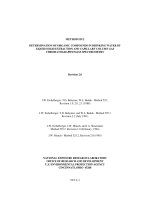
Figure 1.3 is a schematic representation of the chromatographic process.
The horizontal lines represent the column; each line is like a snapshot of
the process at a different time (increasing in time from top to bottom). In
the first snapshot, the sample, composed of components A and B, is introduced onto the column in a narrow zone. It is then carried through the
column (from left to right) by the mobile phase.
Each component partitions between the two phases, as shown by the
distributions or peaks above and below the line. Peaks above the line
represent the amount of a particular component in the mobile phase, and
peaks below the line the amount in the stationary phase. Component A
Direction of mobile-phase flow
Detector
---.
B
+
A
!
Concentrwtion of solute in
mobilephaR
B
A
Concentration of solute in
statiOfllr( phase
B
A
I
i=
t
Chromatogram
D
D
D
A
B
~
A
B
~
o
.
~
Fraction of bed length
Fig. 1.3. Schematic representation of the chromatographic process. From Miller, J. M.,
Chromatography: Concepts and Contrasts, John Wiley & Sons, Inc., New York, 1987, p. 7.
Reproduced courtesy of John Wiley & Sons, Inc.
6
Introduction
has a greater distribution in the mobile phase and as a consequence it is
carried down the column faster than component B, which spends more of
its time in the stationary phase. Thus, separation of A from B Occurs as
they travel through the column. Eventually the components leave the column and pass through the detector as shown. The output signal of the
detector gives rise to a chromatogram shown at the right side of Figure 1.3.
Note that the figure shows how an individual chromatographic peak
widens or broadens as it goes through the chromatographic process. The
exact extent of this broadening, which results from the kinetic processes
at work during chromatography, will be discussed in Chapter 3.
The tendency of a given component to be attracted to the stationary
phase is expressed in chemical terms as an equilibrium constant called the
distribution constant, K e , sometimes also called the partition coefficient.
The distribution constant is similar in principle to the partition coefficient
that controls a liquid-liquid extraction. In chromatography, the greater the
value of the constant, the greater the attraction to the stationary phase.
Alternatively, the attraction can be classified relative to the type of
sorption by the solute. Sorption on the surface of the stationary phase is
called adsorption and sorption into the bulk of a stationary liquid phase is
called absorption. These terms are depicted in comical fashion in Figure
1.4. However, most chromatographers use the term partition to describe
the absorption process. Thus they speak about adsorption on the surface
of the stationary phase and partitioning as passing into the bulk of the
stationary phase. Usually one of these processes is dominant for a given
column, but both can be present.
The distribution constant provides a numerical value for the total sorption by a solute on or in the stationary phase. As such, it expresses the
extent of interaction and regulates the movement of solutes through the
chromatographic bed. In summary, differences in distribution constants
7
Definitions
(parameters controlled by thermodynamics) effect a chromatographic separation.
Some Chromatographic Terms and Symbols
The IUPAC has attempted to codify chromatographic terms, symbols, and
definitions for all forms of chromatography [10], and their recommendations
will be used in this book. However, until the IUPAC publication in 1993,
uniformity did not exist and some confusion may result from reading older
publications. Table 1.1 compares some older conventions with the new
IUPAC recommendations.
The distribution constant, K e , has just been discussed as the controlling
factor in the partitioning equilibrium between a solute and the stationary
phase. It is defined as the concentration of the solute A in the stationary
phase divided by its concentration in the mobile phase.
(1)
This constant is a true thermodynamic value which is temperature dependent; it expresses the relative tendency of a solute to distribute itself between
the two phases. Differences in distribution constants result in differential
migration rates of solutes through a column.
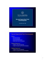
Figure 1.5 shows a typical chromatogram for a single solute, A, with an
additional small peak early in the chromatogram. Solutes like A are retained
by the column and are characterized by their retention volumes, V R ; the
retention volume for solute A is depicted in the figure as the distance from
the point of injection to the peak maximum. It is the volume of carrier gas
TABLE 1.1 Chromatographic Terms and Symbols
Symbol and Name Recommended by
the IUPAC*
K; Distribution constant (for GLC)
K p Partition coefficient
K D Distribution coefficient
k Retention factor
N Plate number
k' Capacity factor; capacity ratio; partition ratio
n Theoretical plate number; no. of theoretical
plates
HETP Height equivalent to one theoretical plate
RR Retention ratio
R
Selectivity; solvent efficiency
H Plate height
ABsorption
ADsorption
Fig. 1.4. Comical illustration of the difference between absorption (partition) and adsorption.
From Miller, J. M., Chromatography: Concepts and Contrasts, John Wiley & Sons, Inc., New
York, 1987, p. 8. Reproduced courtesy of John Wiley & Sons, Inc.
Other Symbols and Names in Use
R Retardation factor (in columns)
R s Peak resolution
a Separation factor
tR Retention time
V R Retention volume
V M Hold-up volume
* Source: Data taken from Ref. to.
Volume of the mobile phase; V G volume of the
gas phase; Vo void volume; dead volume
8
Introduction
I
1
I
I
I
I
I
:
I
! - ,~!----_..:.:----"=-------;~
I
,_
I
I
iii
I
I
:
iii
I-
5.
tJl
: vM
I
"I
I
I
I
Time or volume of mobile phase ~
Fig. 1.5. Typical chromatogram. From Miller, J. M., Chromatography: Concepts and Contrasts, John Wiley & Sons, Inc., New York, 1987, p. 8. Reproduced courtesy of John Wiley &
Sons, Inc.
necessary to elute solute A. This characteristic of a solute could also be
specified by the retention time, tR, ifthe column flow rate, E; were constant".
Overview: Advantages and Disadvantages
9
V represents a volume and the subscripts R, M, and S stand for retention,
mobile, and stationary, respectively. VM and V s represent the volumes of
mobile phase and stationary phase in the column respectively. The retention
volume, V R can be described by reference to Figure 1.5.
An understanding of the chromatographic process can be deduced by
reexamining equation 3. The total volume of carrier gas that flows during
the elution of a solute can be seen to be composed of two parts: the gas
that fills the column or, alternatively, the volume through which the solute
must pass in its journey through the column as represented by V M , and,
second, the volume of gas that flows while the solute is not moving but is
stationary on or in the column bed. The latter is determined by the distribution constant (the solute's tendency to sorb) and the amount of stationary
phase in the column, V s . There are only two things a solute can do: move
with the flow of mobile phase when it is in the mobile phase, or sorb into
the stationary phase and remain immobile. The sum of these two effects
is the total retention volume, V R'
OVERVIEW: ADVANTAGES AND DISADVANTAGES
GC has several important advantages as summarized in the list below.
(2)
Unless specified otherwise, a constant flow rate is assumed and retention
time is proportional to retention volume and both can be used to represent
the same concept.
The small early peak represents a solute that does not sorb in the stationary phase-it passes straight through the column without stopping. In GC,
this behavior is often shown by air or methane, and the peak is often called
an air peak. The symbol V M , sometimes called the hold-up volume or void
volume, serves to measure the interstitial or interparticle volume of the
column. Other IUPAC approved symbols include V o and V G , representing
the volume of the mobile gas phase in the column. The term dead volume,
while not recommended, is also widely used.
Equation 3, one of the fundamental chromatographic equations", relates
the chromatographic retention volume to the theoretical distribution constant.
(3)
b Because the chromatographic column is under pressure, the carrier gas volume is small
at the high-pressure inlet, but expands during passage through the column as the pressure
decreases. This topic is discussed in Chapter 2.
C For a derivation of this equation, see: B. L. Karger, L. R. Snyder, and C. Horvath, An
Introduction to Separation Science, Wiley, NY, 1973, pp. 131 and 166.
Advantages of Gas Chromatography
•
•
•
•
•
•
•
•
Fast analysis, typically minutes
Efficient, providing high resolution
Sensitive, easily detecting ppm and often ppb
Nondestructive, making possible on-line coupling; e.g., to mass spectrometer
Highly accurate quantitative analysis, typical RSDs of 1-5%
Requires small samples, typically IJ-L
Reliable and relatively simple
Inexpensive
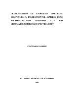
Chromatographers have always been interested in fast analyses, and GC
has been the fastest of them all, with current commercial instrumentation
permitting analyses in seconds. Figure 1.6 shows a traditional orange oil
separation taking 40 minutes, a typical analysis time, and a comparable
one completed in only 80 seconds using instrumentation specially designed
for fast analysis.
The high efficiency of GC was evident in Figure 1.1. Efficiency can be
expressed in plate numbers, and capillary columns typically have plate
numbers of several hundred thousand. As one might expect, an informal
competition seems to exist to see who can make the column with the
10
Introduction
11
Overview: Advantages and Disadvantages
ORANGE OIL, 1000 PPM in ISOOCTANE
(a) Industry Standard
Conditions not reported
Components:
1 - Ethyl Butyrate
2 - Isomyl acetate
3 - (alpha)-pinene
4 - Myrcene
5 - Octanal
6 - p-Cymene
, 7 - Limonene
8 - Linalool
9 - 4-terpineol
10 - (alpha)-terpineol
11 - Decanal
12 - Neral
13 - Carvone
14 - Geranail
15 - Perillaldehyde
16 - URdecanal
17 - Dodecanal
18 - (alpha)-ionone
19 - Cadinene
20 - Int.
(b)
3
7
o
40
"asb-2D-GC
Column: DB-5, 6 meters, 0.25 mm 10,
0.25 umfilm thickness
Temp: initial temp. 60° C
ramp to 65° C at 25 sec
ramp to 80° C at 50 sec
ramp to 100° C at 60 sec
ramp to 225° C at 80 sec
Carrier: Hydrogen
How: 4 mUmin.
Velosity: 100 em/sec.
Split: 50:1
Detector: FlD
greatest plate count-the "best" column in the world-and since column
efficiency increases with column length, this has led to a competition to
make the longest column. Currently, the record for the longest continuous
column is held by Chrompack International [11] who made a 1300-m fused
silica column (the largest size that would fit inside a commercial GC oven).
It had a plate number of 1.2 million which was smaller than predicted, due
in part to limits in the operational conditions.
Recently, a more efficient column was made by connecting nine 50-m
columns into a single one of 450 m total length [12]. While much shorter
than the Chrompack column, its efficiency was nearly 100% of theoretical,
and it was calculated to have a plate number of 1.3 million and found
capable of separating 970 components in a gasoline sample.
Because GC is excellent for quantitative analysis, it has found wide use
for many different applications. Sensitive, quantitative detectors provide
fast, accurate analyses, and at a relatively low cost. A pesticide separation
illustrating the high speed, sensitivity, and selectivity of GC is shown in
Figure 1.7.
GC has replaced distillation as the preferred method for separating
volatile materials. In both techniques, temperature is a major variable, but
gas chromatographic separations are also dependent upon the chemical
nature (polarity) of the stationary phase. This additional variable makes
GC more powerful. In addition, the fact that solute concentrations are very
dilute in GC columns eliminates the possibility of azeotropes, which often
plagued distillation separations.
Both methods are limited to volatile samples. A practical upper temperature limit for GC operation is about 380aC so samples need to have an
appreciable vapor pressure (60 torr or greater) at that temperature. Solutes
usually do not exceed boiling points of 500aC and molecular weights of
20
II
13
16 I
IS
19
1
3pg
Malathion
o
10
20
30
40
so
60
70
3pg
10
@
®
SECONDS
Ethion
3pg
Fig. 1.6. Comparison of orange oil separations; (a) a conventional separation (b) a fast
separation on a Flash-GC instrument. Reprinted with permission of Thermedics Detection.
1
2
3
4
Minutes
Fie. 1.7.
Pesticide separation showine both hioh sneed and low dptprtivitv
12
Introduction
13
References
Solid Support
Liquid Phase
1,000 Daltons. This major limitation of GC is listed below along with other
disadvantages of G'C,
Disadvantages of Gas Chromatography
•
•
•
•
Limited to volatile samples
Not suitable for thermally labile samples
Fairly difficult for large, preparative samples
Requires spectroscopy, usually mass spectroscopy, for confirmation of
peak identity
In summary: for the separation of volatile materials, GC is usually the
method of choice due to its speed, high resolution capability, and ease of use.
1/8" o.d.
(a) Packed column
0.25 mm i.d.
(b) Capillary orWCOT
INSTRUMENTATION
Fig. 1.9. Schematic representation of (a) packed column and (b) open tubular column.
Figure 1.8 shows the basic parts of a simple gas chromatograph-carrier
gas, flow controller, injector, column, detector, and data system. More detail
is given in the next chapter.
The heart of the chromatograph is the column; the first ones were metal
tubes packed with inert supports on which stationary liquids were coated.
Today, the most popular columns are made of fused silica and are open
tubes (OT) with capillary dimensions. The stationary liquid phase is coated
on the inside surface of the capillary wall. The two types are shown in
Detector
CD
CD
®
Data System
Gas
Cylinder
® Oven
Fig. 1.8. Schematic of a typical gas chromatograph.
Figure 1.9 and each type is treated in a separate chapter-packed columns
in Chapter 5 and capillary columns in Chapter 6.
REFERENCES
1.
2.
3.
4.
5.
6.
7.
8.
9.
10.
McNair. H .. LC-GC, 10,239 (1992).
Ramsey, W., Proc. Roy. Soc. A76, 111 (1905).
Tswett, M.• Ber. dew. botan. Ges., 24,316 and 384 (1906).
Strain, H. H.• and Sherrna, J.• J. Chern. Educ., 44,238 (1967).
James. A. T.. and Martin, A. J. P.• Biochem. J., 50,679 (1952).
Martin. A. J. P.. and Synge. R. L. M.• Biochem. J., 35, 1358 (1941).
Ettre. L. S.• Anal. Chern., 43, [14], 20A-31A (1971)
Ellre. L. S., LC-GC, 8,716-724 (1990).
Ettre. L. S.. J. Chrornatogr. 112, 1-26 (1975).
Ettre, L. S.. Pure & Appl. Chern., 65, 819-872 (1993). See also. Ettre, L. S.. LC-GC, 11,
502 (1993).
11. de Zeeuw, J., Chrompack International B. Y., Middleburg, the Netherlands. personal
communication, 1996.
12. Berger. T. A.. Chromatographia, 42,63 (1996).
15
Carrier Gas
Detector
FID
Injector/Splitter
I--C(}-- Air
::r-iX)--, Make-up He
2.
Instrument Overview
Pressure
gauge
He
carrier
In
Fig. 2.1. Schematic of a typical gas chromatograph.
Instrumentation in gas chromatography has continually evolved since the
introduction of the first commercial systems in 1954. The basic components
of a typical, modern gas chromatographic system are discussed individually
in this chapter.
Figure 2.1 shows schematically a gas chromatographic system. The components which will be discussed include: (1) carrier gas; (2) flow control;
(3) sample inlet and sampling devices; (4) columns; (5) controlled temperature zones (ovens); (6) detectors; and (7) data systems.
In summary, a gas chromatograph functions as follows. An inert carrier
gas (like helium) flows continuously from a large gas cylinder through the
injection port, the column, and the detector. The flow rate of the carrier
gas is carefully controlled to ensure reproducible retention times and to
minimize detector drift and noise. The sample is injected (usually with a
microsyringe) into the heated injection port where it is vaporized and
carried into the column, typically a capillary column 15 to 30 m long, coated
on the inside with a thin (0.2 JLm) film of high boiling liquid (the stationary
phase). The sample partitions between the mobile and stationary phases,
and is separated into individual components based on relative solubility in
the liquid phase and relative vapor pressures.
After the column, the carrier gas and sample pass through a detector.
This device measures the quantity of the sample, and generates an electrical
signal. This signal goes to a data system/integrator which generates a chromatogram (the written record of analysis). In most cases the data-handling
system automatically integrates the peak area, performs calculations and
prints out a report with quantitative results and retention times. Each of
these seven components will be discussed in greater detail.
CARRIER GAS
The main purpose of the carrier gas is to carry the sample through the
column. It is the mobile phase and it is inert and does not interact chemically
with the sample.
A secondary purpose is to provide a suitable matrix for the detector to
measure the sample components. Below are the carrier gases preferred for
various detectors:
CARRIER GASES AND DETECTORS
Detector
Carrier Gas
Thermal conductivity
Flame ionization
Electron capture
Helium
Helium or nitrogen
Very dry nitrogen or
Argon, 5% methane
Instrument Overview
16
For the thermal conductivity detector, helium is the most popular. While
hydrogen is commonly used in some parts of the world (where helium is
very expensive), it is not recommended because of the potential for fire
and explosions. With the flame ionization detector, either nitrogen or helium may be used. Nitrogen provides slightly more sensitivity, but a slower
analysis than helium. For the electron capture detector, very dry, oxygenfree nitrogen, or a mixture of argon with 5% methane is recommended.
Purity
It is important that the carrier gas be of high purity because impurities
such as oxygen and water can chemically attack the liquid phase in the
column and destroy it. Polyester, polyglycol and polyamide columns are
particularly susceptible. Trace amounts of water can also desorb other
column contaminants and produce a high detector background or even
"ghost peaks." Trace hydrocarbons in the carrier gas cause a high background with most ionization detectors and thus limit their detectability.
One way to obtain high purity carrier gas is to purchase high purity gas
cylinders. The following list compares the purity and prices for helium
available in the United States:
HELIUM SPECIFICATIONS AND PRICES
Quality
Purity
Price
Research grade
Ultrapure
High purity
99.9999%
99.999%
99.995%
$280
$140
$55
Prices are quoted for a cylinder containing 49 liters (water capacity) and
rated at 2400 psi. Obviously, purchasing the carrier gas of adequate purity
is not economically feasible for most laboratories.
The more common practice is to purchase the High Purity grade and
purify it. Water and trace hydrocarbons can be easily removed by installing
a 5A molecular sieve filter between the gas cylinder and the instrument.
Drying tubes are commercially available, or they can be readily made by
filling a 6-ft. by 114" column with GC grade 5A molecular sieve. In either
case, after two gas cylinders have been used, the sieve should be regenerated
by heating to 300°C for 3 hours with a slow flow of dry nitrogen. If homemade, the 6-ft. column can be coiled to fit easily into the chromatographic
column oven for easy regeneration.
Oxygen is more difficult to remove and requires a special filter, such as
a BTS catalyst from BASF, Ludwigshaven am Rhein, Oxisorb from Supelco,
or Dow Gas Purifier from Alltech.
Flow Control and Measurement
17
FLOW CONTROL AND MEASUREMENT
The measurement and control of carrier gas flowis essential for both column
efficiency and for qualitative analysis. Column efficiency depends on the
proper linear gas velocity which can be easily determined by changing the
flow rate until the maximum plate number is achieved. Typical optimum
values are: 75 to 90 mLimin for 114" outside diameter (o.d.) packed columns;
25 mLimin for 118" o.d. packed columns; and 0.75 mLimin for a 0.25 JLm
i.d. open tubular column. These values are merely guidelines; the optimum
value for a given column should be determined experimentally.
For qualitative analysis, it is essential to have a constant and reproducible
flow rate so that retention times can be reproduced. Comparison of retention times is the quickest and easiest technique for compound identification.
Keep in mind that two or more compounds may have the same retention
time, but no compound may have two different retention times. Thus,
retention times are characteristic of a solute, but not unique. Obviously,
good flow control is essential for this method of identification.
Controls
The first control in any flow system is a two-stage regulator connected to
the carrier gas cylinder to reduce the tank pressure of 2,500 psig down to
a useable level of 20-60 psig. It should include a safety valve and an
inlet filter to prevent particulate matter from entering it. A stainless steel
diaphragm is recommended to avoid any air leaks into the system. The
first gauge indicates the pressure left in the gas cylinder. By turning the
valve on the second stage, an increasing pressure will be delivered to the
gas chromatograph and will be indicated on the second gauge. The second
stage regulator does not work well at low pressures and it is recommended
that a minimum of 20 psi be used.
For isothermal operation, constant pressure is sufficient to provide a
constant flow rate, assuming that the column has a constant pressure drop.
For simple, inexpensive gas chromatographs which run only isothermally,
the second part of the flow control system may be a simple needle valve;
this, however, is not sufficient for research systems.
In temperature programming, even when the inlet pressure is constant,
the flow rate will decrease as the column temperature increases. As an
example, at an inlet pressure of 24 psi and a flow rate of 22 mLimin (helium)
at 50°C, the flow rate decreases to 10 mLimin at 200°C. This decrease is
due to the increased viscosity of the carrier gas at higher temperatures. In all
temperature-programmed instruments, and even in some better isothermal
ones, a differential flowcontroller is used to assure a constant mass flow rate.
Sometimes, however, it is not desirable to control the flow rate with
such a controller. For example, split and splitless sample injection both
denend on :l constant nrp.~~lJrp for rorrprt fllnrtinninn rnnd<:lnt nr"~~,,r"
18
Instrument Overview
maintains the same flow rate through the column, independent of the
opening and closing of the purge valve. Under these conditions, the carrier
gas pressure can be increased electronically during a programmed run in
order to maintain a constant flow. An electronic sensor is used to detect
the (decreasing) flow rate and increase the pressure to the column, thus
providing a constant flow rate by electronic pressure control (EPe).
Flow Measurement
The two most commonly used devices are a soap-bubble flowmeter and a
digital electronic flow measuring device (Fig. 2.2). The soap-film flowmeter
is merely a calibrated tube (usually a modified pipet or buret) through
which the carrier gas flows. By squeezing a rubber bulb, a soap solution is
raised into the path of the flowing gas. After several soap bubbles are
allowed to wet the tube, one bubble is accurately timed through a defined
volume with a stopwatch. From this measurement, the carrier gas flow rate
in mlzmin is easily calculated. Some electronic flow meters are based on
the same principle, but the measurements are made with light beams. At
a cost around $300, an electronic flow meter is faster and easier to use
and provides a three-digit readout of the flow rate.
'
19
Flow Control and Measurement
Another, more sophisticated electronic device uses a solid-state sensor
coupled with a microprocessor to permit accurate flow measurements for
a range of gases without using soap bubbles. A silicone-on-ceramic sensor
can be used to measure flow rates of 0.1 to 500 mL/min for air, oxygen,
nitrogen, helium, hydrogen, and 5% argon in methane. The cost for this
device is about $500.
Very small flow rates such as those encountered in open tubular columns,
cannot be measured reliably with these meters. The average linear flow
velocity in OT columns, ii, can be calculated from equation 1:
u
L
=tM
where L is the length of the column (em) and tM is the retention time for
a nonretained peak such as air or methane (seconds). Since the flame
detector does not detect air, methane is usually used for this measurement,
but the column conditions must be chosen (high enough temperature) so
that it is not retained. Conversion of the linear velocity in ern/sec to flow
Gas from
chromatograph
I
Soap
(a)
Fig. 2.2. Flow meters: (a) soap film type (b) digital electronic type.
(1)
(b)
Fig. 2.2. (Continued).
20
Instrument Overview
rate (in mLimin) is achieved by multiplying by the cross-sectional area of
the column (1Tr2). See Appendix IV.
SAMPLE INLETS
Compressibility of the Carrier Gas
Since the carr~er gas entering a GC column is under pressure and the
column outlet IS usually at atmospheric pressure, the inlet pressure p is
greate~ than the outlet pressure, Po. Consequently, the gas is comp;es~ed
at the Inlet an? expands as it passes through the column; the volumetric
flow rate also Increases !rom the head of the column to the outlet.
Us~ally the volumetnc flow rate is measured at the outlet where it is at
a m~I~um. To get the average flow rate, Fe, the outlet flow must be
multIphed by the so-called compressibility factor, j:
j~~m~r~J
(2)
and:
Fe
=j
X
Fe
(3)
Some typical values of j are given in the Appendix VII.
If one calculates a retention volume from a retention time, the avera e
flow rate shoul~ be used, and the resulting retention volume is called t~e
corrected retention volume , TVJO.
it.
21
Sample Inlets and Sampling Devices
Packed Column
Capillary Column
Flash vaporizer
On-column
Split
Splitless
On-column
Ideally, the sample is injected instantaneously onto the column, but in
practice this is impossible and a more realistic goal is to introduce it as a
sharp symmetrical band. The difficulty keeping the sample sharp and narrow
can be appreciated by considering the vaporization of a 1.0 microliter
sample of benzene. Upon injection, the benzene vaporizes to 600 JLL of
vapor. In the case of a capillary column (at a flow rate of 1 mLlmin), 36
seconds would be required to carry it onto the column. This would be so
slow that an initial broad band would result and produce very poor column
performance (low N). Clearly, sampling is a very important part of the
chromatographic process and the size of the sample is critical.
There is no single optimum sample size. Some general guidelines are
available, however. Table 2.1 lists typical sample sizes for three types of
columns. For the best peak shape and maximum resolution, the smallest
possible sample size should always be used.
The more components present in the sample, the larger the sample size
may need to be. In most cases, the presence of other components will not
affect the location and peak shape of a given solute. For trace work, and
for preparative-scale work, it is often best to use large sample sizes even
though they will "overload" the column. The major peaks may be badly
distorted, but the desired (trace) peaks will be larger, making it possible
to achieve the desired results.
Gas Sampling
(4)
T his term sh~uld not be confused with the adjusted retention volume to
be presented In the next chapter.
Gas sampling methods require that the entire sample be in the gas phase
under the conditions in use. Mixtures of gases and liquids pose special
problems. If possible, mixtures should either be heated, to convert all
components to gases, or pressurized, to convert all components to liquids.
Unfortunately, this is not always possible.
SAMPLE INLETS AND SAMPLING DEVICES
TABLE 2.1 Sample Volumes for Different Column Types
The.~amPle inl~t should handle a wide variety of samples inclUding gases
Column Types
~qU1 dS: and ~Ohds, ~nd permit them to be rapidly and quantitatively intro~
uce Into t e c~rner gas.str~am. Different column types require different
types of sample Inlets as indicatsr] in the following list:
Sample Sizes (liquid)
Regular analytical packed: t" o.d., 10% liquid
High efficiency packed: i" o.d., 3% liquid
Capillary (open tubular): 250 ILm i.d., 0.2 ILm film
* These sample sizes are often obtained by sample splitting techniques.
0.2-20 ILl
0.01-2 ILI*
0.01-3 ILI*
22
Instrument Overview
Gas-tight syringes and gas sampling valves are the most commonly used
methods for gas sampling. The syringe is more flexible, less expensive and
the most frequently used device. A gas-sampling valve on the hand gives
better repeatability, requires less skill and can be more easily automated.
Refer to Chapter 5 for more details on valves.
Liquid Sampliug
Since liquids expand considerably when they vaporize, only small sample
sizes are desirable, typically microliters. Syringes are almost the universal
method for injection of liquids. The most commonly used sizes for liquids
are 1, 5, and 10 microliters. In those situations where the liquid samples
are heated (as in all types of vaporizing injectors) to allow rapid vaporization
before passage in.to the column, care must be taken to avoid overheating
that could result In thermal decomposition.
Solid Sampling
Solids are best handled by dissolving them in an appropriate solvent, and
by using a syringe to inject the solution.
Syringes
Figure 2.3 shows a lO-microliter liquid syringe typically used for injecting
one .to fiv~ ~icroliters ?~ liquids or solutions. The stainless steel plunger
fits tightly inside a precision barrel made of borosilicate glass. The needle,
also stainless steel, is epoxyed into the barrel. Other models have a removable needle that screws onto the end of the barrel. For smaller volumes a
1-m~c~olit.er syringe is also available. A lO-milliliter gas-tight syringe is us~d
for mjectmg gaseous samples up to about 5 milliliters in size. A useful
suggestion is to always use a syringe whose total sample volume is at least
two times larger than the volume to be injected.
Using a Syringe
In filling a microliter syringe with liquid, it is desirable to exclude all air
initially. This can be accomplished by repeatedly drawing liquid into the
syringe and rapidly expelling it back into the liquid. Viscous liquids must
be drawn into the syringe slowly; very fast expulsion of a viscous liquid
NEEDLE
+
BARREL
o
!1'0' "1*"11'1""
Fig. 2.3. Microsyringe, lOJLL volume.
Sample Inlets and Sampling Devices
23
could split the syringe. If too viscous, the sample can be diluted with an
appropriate solvent.
. .
Draw up more liquid into the syringe than you plan to Inject. Hold the
syringe vertically with the needle pointing up so any air still in the syringe
will go to the top of the barrel. Depress the plunger until it reads the
desired value; the excess air should have been expelled. Wipe off the needle
with a tissue, and draw some air into the syringe now that the exact volume
of liquid has been measured. This air will serve two purposes: first, it will
often give a peak on the chromatogram, which can be used to measure
tM; second, the air prevents any liquid from being lost if the plunger is
accidentally pushed.
To inject, use one hand to guide the needle into the septum and the
other to provide force to pierce the septum and also to prevent the plunger
from being blown out by the pressure in the GC. The latter point is important when large volumes are being injected (e.g., gas samples) or when the
inlet pressure is extremely high. Under these conditions, if care is not
exercised, the plunger will be blown out of the syringe.
Insert the needle rapidly through the septum and as far into the injection
port as possible and depress the plunger, wait a second or two, then withdraw the needle (keeping the plunger depressed) as rapidly and smoothly
as possible. Note that alternate procedures are often used with open tubular
columns. Be careful; most injection ports are heated and you can easily
burn yourself.
Between samples, the syringe must be cleaned. When high-boiling liquids
are being used, it should be washed with a volatile solvent like methylene
chloride or acetone. This can be done by repeatedly pulling the wash liquid
into the syringe and expelling it. Finally, the plunger is removed and the
syringe dried by pulling air through it with a vacuum pump (appropriately
trapped) or a water aspirator. Pull the air in through the needle so dust
cannot get into the barrel to clog it. Wipe the plunger with a tissue and
reinsert. If the needle gets dulled, it can be sharpened on a small grindstone.
Autosamplers
Samples can be injected automatically with mechanical devices that are
often placed on top of gas chromatographs. These autosamplers mimic the
human injection process just described using syringes. After flushing with
solvent, they draw up the required sample several times from a sealed vial
and then inject a fixed volume into the standard GC inlet. Autosamplers
consist of a tray which holds a large number of samples, standards, and
wash solvents, all of which are rotated into position under the syringe as
needed. They can run unattended and thus allow many samples to be run
overnight. Autosamplers provide better precision than manual injectiontypically 0.2% relative standard deviation (RSD).
Instrument Overview
24
Septa
Syringe injection is accomplished through a self-sealing septum, a polymeric
silicone with high-temperature stability. Many types of septa are commercially available; some are composed of layers and some have a film of
Teflon'" on the column side. In selecting one, the properties that should
be considered are: high temperature stability, amount of septum "bleed"
(decomposition), size, lifetime, and cost.
25
Temperature Zones
called "wall-coated open tubular" or simply WCOT columns. Since the
tube is open, its resistance to flow is very low; therefor~, long leng~hs,
to 100 meters, are possible. These long lengths permit very efficient
~~parations of complex sample mixtures. Fused silica capilla~y colu~~s
are the most inert. Open tubular (OT) columns are covered m detail m
Chapter 6.
.
h .
Table 2.2 compares these two main types of column and lists t err
advantages, disadvantages, and some typical applications.
COLUMNS
TEMPERATURE ZONES
Figure 2.4 shows schematically a packed column in a longitudinal cross
section. The column itself is usually made of stainless steel and is packed
tightly with stationary phase on an inert solid support of diatomaceous
earth coated with a thin film of liquid. The liquid phase typically constitutes
3, 5, or 10% by weight of the total stationary phase.
'Packed columns are normally three, six, or twelve feet in length. The
outside diameter is usually 114" or 118". Stainless steel is used most often,
primarily because of its strength. Glass columns are more inert, and they
are often used for trace pesticide and biomedical samples that might react
with the more active stainless steel tubing.
Packed columns are easy to make and easy to use. A large variety of
liquid phases is available. Because the columns are tightly packed with
small particles, lengths over 20 feet are impractical, and only a modest
number of plates is usually achieved (about 8,000 maximum). Packed columns are covered in detail in Chapter 5.
Capillary columns are simple chromatograpic columns, which are not
filled with packing material. Instead, a thin film of liquid phase coats the
inside wall of the 0.25 mm fused silica tubing. Such columns are properly
The column is thermostated so that a good separatio~ w.ill occur in a
reasonable amount of time. It is often necessary to maintain the column
at a wide variety of temperatures, from ambient ~o 360°C. T~e control of
temperature is one of the easiest and most effective a.ys ~o influence the
separation. The column is fixed bet.ween a .heated injection port and a
heated detector, so it seems appropnate to dISCUSS the temperature levels
at which these components are operated.
v:
Injection-port Temperature
The injection port should be hot enough ~o. va~orize the. sample rapidly so
that no loss in efficiency results from the injection techmque. On the other
hand, the injection-port temperature must be low enough so that thermal
decomposition or chemical rearrangement is avoid.ed.
.. .
For flash vaporization injection, a general rule IS to have the injection
temperature about 50°C hotter than the boil~n~ P?int of the sample. A
practical test is to raise the temperature of the mjecnon port. If the column
TABLE 2.2 Comparison of Packed and WCOT Columns
Mobile Phase
(Carrier Gas)
Solid
Support
Liquid (Stationary) Phase
Outside diameter
Inside diameter
3.2mm
2.2mm
0.40 mm
0.25 mm
d,
5JLm
0.25 JLm
f3
Column length
Flow
15-30
1-2 m
20 mL/min
N to !
4,000
n.:
Advantages
Fig. 2.4. Packed column, longitudinal cross section.
WCOT
i" Packed
0.5 mm
Lower cost
Easier to make
Easier to use
Larger samples
Better for fixed gases
250
15-60 m
1 mL/min
180,000
0.3mm
Higher efficiency
Faster
More inert
Fewer columns needed
Better for complex mixtures
26
Instrument Overview
~~~Ci;;~~ or Pt eat~ shape improves,
the injection-port temperature was too
.
e re en IOn time, the peak area or the sha
h
.
the temperature may be too high and 'de
. ~e c anges drastically,
h
composmon or rearrangeme t
may ave occurred. For on-column injection the inlet t
n
be lower.
'
emperature can
Data Systems
27
temperature with time. Temperature programming is very useful for wide
boiling sample mixtures and is very popular. Further details can be found
in Chapter 9.
Detector Temperature
Column Temperature
The column temperature should be high enough so that sam le com
pa~s through It at a ~easonable speed. It need not be higher fhan tht~n.~~ts
POInto! the sample; In fact is is usually preferable if the colum t
01 mg
the boiling point. If that seems illogic:l,e~~;:~~;
~ co umn oper~tes at a temperature where the sample is in the va
state-It need not be In the gas state In GC th
I
por
~~;tO~SIde~abIY below
::~i:~~;~ "~e~pOin~'
i: ~~t~:v~e::~~~~;ep:~~~
be
t;e
of the 'sam?le:
110, and 1300C ' ~t ~5;~ctahr on sample IS run on the same column at 75,
.
e vapor pressures of the sam I
are low and they move slowly through the column. Two is~;e~~~fon:nts
are well resolved before the C-8 eak: h
"
oc ane
long, at 24 minutes.
p
, owever, the analysis time is very
12 At higher te~perat~res, the retention times decrease. At 110°C the Cpeak IS out In 8 mmutes and by 130°C the an I . .
. t b '
a ySIS IS complete in 4
mmu es, ut the resolution decreases. Notice that the t
.
no longer resolved at the high t
oc ane Isomers are
longer analysis times, but bette~r:s~fu~~~~~re. Lower temperature means
Isothermal vs, Programmed Temperature (PTGC)
Isothermal denotes a chromatographic analysis at one constant colu
temperature. Programmed temperature refers to a linear increase of column
The detector temperature depends on the type of detector employed. As
a general rule, however, the detector and its connections from the column
exit must be hot enough to prevent condensation of the sample and/or
liquid phase. If the temperature is too low and condensation occurs, peak
broadening and even the total loss of peaks is possible.
The thermal conductivity detector temperature must be controlled to
±O.l°C or better for baseline stability and maximum detectivity. Ionization
detectors do not have this strict a requirement; their temperature must be
maintained high enough to avoid condensation of the samples and also of
the water or by-products formed in the ionization process. A reasonable
minimum temperature for the flame ionization detector is 125°e.
DETECTORS
A detector senses the effluents from the column and provides a record of
the chromatography in the form of a chromatogram. The detector signals
are proportionate to the quantity of each solute (analyte) making possible
quantitative analysis.
The most common detector is the flame ionization detector, FID. It has
the desirable characteristics of high sensitivity, linearity, and detectivity
and yet it is relatively simple and inexpensive. Other popular detectors are
the thermal conductivity cell (TCD) and the electron capture detector
(ECD). These and a few others are described in Chapter 7.
n-C-B
C-l0
C-ll
DATA SYSTEMS
OctaneIsomers
12
16
C -12
,
o
110°C
2
4
Fig. 2.5. Effect of temperature on retention time.
Since OT columns produce fast peaks, the major requirement of a good
data system is the ability to measure the GC signal with rapid sampling
rates. Currently there is an array of hardware, made possible by advances
in computer technology, that can easily perform this function. In general,
there are two types of systems in common use-integrators and computers.
Microprocessor-based integrators are simply hard wired, dedicated micro
processors which use an analog-to-digital (A-to-D) converter to produce
both the chromatogram (analog signal) and a digital report for quantitative
analysis. They basically need to calculate the start, apex, end, and area of
each peak. Algorithms to perform these functions have been available for
some time.
28
Instrument Overview
Most integrators perform area percent, height percent, internal standard,
external standard, and normalization calculations. For nonlinear detectors,
multiple standards can be injected, covering the peak area of interest, and
software can perform a multilevel calibration. The operator then chooses
an integrator calibration routine suitable for that particular detector output.
Many integrators provide BASIC programming, digital control of instrument parameters, and automated analysis, from injection to cleaning of the
column and injection of the next sample. Almost all integrators provide
an RS-232-C interface so the GC output is compatible with "in house"
digital networks.
Personal computer-based systems have now successfully migrated to the
chromatography laboratory. They provide easy means to handle single or
multiple chromatographic systems and provide output to both local and
remote terminals. Computers have greater flexibility in acquiring data,
instrument control, data reduction, display and transfer to other devices.
The increased memory, processing speed and flexible user interfaces make
them more popular than dedicated integrators. Current computer-based
systems rely primarily on an A-to-D card, which plugs into the PC main
frame. Earlier versions used a separate stand-alone A-to-D box or were
interfaced to stand-alone integrators. As costs for PCs decrease, their popularity will undoubtedly increase.
3.
Basic Concepts and Terms
In Chapter 1, definitions and terms were presented to facilitate the description of the chromatographic system. In this chapter, additional terms are
introduced and related to the basic theory of chromatography. Please refer
to Table 1.1 in Chapter 1 for a listing of some of the symbols. Make special
note of those that are recommended by the IUPAC; they are the ones used
in this book.
This chapter continues with a presentation of the Rate Theory, which
explains the processes by which solute peaks are broadened as they pass
through the column. Rate theory treats the kinetic aspects of chromatography and provides guidelines for preparing efficient columns-columns that
keep peak broadening to a minimum.
DEFINITIONS, TERMS, AND SYMBOLS
Distribution Constant
A thermodynamic equilibrium constant called the distribution constant, K;
was presented in Chapter 1 as the controlling parameter in determining
how fast a given solute moves down a GC column. For a solute or analyte
designated A,
K
=
c
[A]s
[A]M
29
(1)
Basic Concepts and Terms
30
where the brackets denote molar concentrations and the subscripts Sand
M refer to the stationary and mobile phases respectively. The larger the
distribution constant, the more the solute sorbs in the stationary phase,
and the longer it is retained on the column. Since this is an equilibrium
constant, one would assume that chromatography is an equilibrium process.
Clearly it is not, because the mobile gas phase is constantly moving solute
molecules down the column. However, if the kinetics of mass transfer are
fast, a chromatographic system will operate close to equilibrium and thus
the distribution constant will be an adequate and useful descriptor.
Another assumption not usually stated is that the solutes do not interact
, with one another. That is, molecules of solute A pass through the column
as though no other solutes were present. This assumption is reasonable
because of the low concentrations present in the column and because the
solutes are increasingly separated from each other as they pass through
the column. If interactions do occur, the chromatographic results will deviate from those predicted by the theory; peak shapes and retention volumes
may be affected.
31
Definitions, Terms, and Symbols
helpful in selecting the proper column. Some typical values are given in
Table 3.1.
The retention factor, k, is the ratio of the amount of solute (not the
concentraion of solute) in the stationary phase to the amount in the mobile phase:
(6)
The larger this value, the greater the amount of a given solute in the
stationary phase, and hence, the longer it will be retained on the column.
In that sense, retention factor measures the extent to which a solute is
retained. As such, it is just as valuable a parameter as the distribution
constant, and it is one that can be easily evaluated from the chromatogram.
To arrive at a useful working definition, equation 2 is rearranged and
equation 3 is substituted into it, yielding:
(7)
Retention Factor
In making use of the distribution constant in chromatography, it is useful
to break it down into two terms.
K;
=k
X
{3
Recalling the basic chromatographic equation introduced in Chapter 1,
VR
(2)
=
V M + KeVs
(8)
{3 is the phase volume ratio and k is the retention factor.
TABLE 3.1 Phase Volume Ratios (fJ) for Some Typical Colamns"
{3
= VM
Vs
(3)
For capillary columns whose film thickness, d-, is known, {3 can be calculated
by using equation 4,
(4)
Column
Type b
I. D.
(mm)
A
B
C
PC
PC
SCOT
WCOT
WCOT
WCOT
WCOT
WCOT
WCOT
WCOT
WCOT
WCOT
2.16
2.16
0.50
0.10
0.10
0.25
0.32
0.32
0.32
0.32
0.53
0.53
D
E
F
G
where r c is the radius of the capillary column. If, as is usually the case,
rc ~ d., equation 4 reduces to:
{3
= .Is:
2 df
(5)
H
I
J
K
L
2
2
15
30
30
30
30
30
30
30
30
30
Film c
Thickness
(IA-m)
10%
5%
0.10
0.25
0.25
0.32
0.50
1.00
5.00
1.00
5.00
Vo
(mL)
f3
H
(mm)
Jel
2.94
2.94
2.75
0.24
0.23
1.47
2.40
2.40
2.38
2.26
6.57
6.37
12
26
20
249
99
249
249
159
79
15
132
26
0.549
0.500
0.950
0.063
0.081
0.156
0.200
0.228
0.294
0.435
0.426
0.683
10.375
4.789
6.225
0.500
1.258
0.500
0.500
0.783
1.576
8.300
0.943
4.789
Taken from Ref. 1. Reprinted with permission of the author.
Type: PC = Packed Column
SCOT = Support-coated Open Tubular
WCOT = Wall-coated Open Tubular
C For packed columns: liquid stationary phase loading in weight percent.
d Relative values based on column G having k = 0.5.
a
b
For capillary columns, typical {3-values are in the hundreds, about 10
times the value in packed columns for which {3 is not as easily evaluated.
The phase volume ratio is a very useful parameter to know and can be
Length
(m)
32
Basic Concepts and Terms
and rearranging it produces a new term, V~, the adjusted retention volume.
33
Definitions, Terms, and Symbols
(9)
sibility of the carrier gas and-based on the average flow rate. There is still
another retention volume representing the value that is both adjusted and
corrected; it is called the net retention volume, V N:
It is the adjusted retention volume which is directly proportional to the
(11)
thermodynamic distribution constant and therefore the parameter often
used in theoretical equations. In essence it is the retention time measured
from the nonretained peak (air or methane) as was shown in Figure 1.5.
Rearranging equation 9 and substituting it into equation 7 yields the
, useful working definition of k:
k
=
~: = (~:) -
(10)
1
Since both retention volumes, V~ and VM , can be measured directly from
a chromatogram, it is easy to determine the retention factor for any solute
as illustrated in Figure 3.1. Relative values of k are included in Table 3.1
to aid in the comparison of the column types tabulated there.
Note that the more a solute is retained by the stationary phase, the
larger is the retention volume and the larger is the retention factor. Thus,
even though the distribution constant may not be known for a given solute,
the retention factor is readily measured from the chromatogram, and it can
be used instead of the distribution constant to measure the relative extent
of sorption by a solute. However, if /3 is known (as is usually the case for
OT columns), the distribution constant can be calculated from equation 2.
Because the definition of the adjusted retention volume was given above,
and a related definition of the corrected retention volume was given in
Chapter 2 (equation 4), we ought to make sure that these two are not
confused with one another. Each has its own particular definition: the
adjusted retention volume, V~ is the retention volume excluding the void
volume (measured from the methane or air peak) as shown in equation 9;
the corrected retention volume, ~, is the value correcting for the compres-
Consequently, for GC, equation 9 should more appropriately be written as:
(12)
Depending on the particular point they are making, gas chromatographers
feel free to substitute the adjusted retention volume in situations where
they should be using the net retention volume. In LC, there is no significant
compressibility of the mobile phase and the two values can be used interchangeably.
Retardation Factor
Another way to express the retention behavior of a solute is to compare
its velocity through the column, /L, with the average" velocity of the mobile
gas phase,
u:
t;;=R
u
(13)
The new parameter defined by equation 13 is called the retardation factor,
R. While it is not too widely used, it too can be calculated directly from
chromatographic data, and it bears an interesting relationship to k.
To arrive at a computational definition, the solute velocity can be calculated by dividing the length of the column, L, by the retention time of a
given solute,
(14)
Non-retained
k=1
k=2
k=3
where L is in cm or mm and the retention time is in seconds. Similarly,
the average linear gas velocity is calculated from the retention time for a
nonretained peak like air:
(15)
o
2
3
Time (mins) _
4
Fig. 3.1. Illustration of retention factor, k.
a Remember from Chapter 2 that the linear velocity of the mobile phase varies through
the column due to the compressibility of the carrier gas, so the value used in equation 12 is
the average linear velocity, usually designated as u.
Basic Concepts and Terms
34
Combining equations 10, 13, and 14 yields the computational definition
of the retardation factor:
35
Definitions, Terms, and Symbols
a.ldeal
b.Broad
c. Fronting d. Tailing e. Doublet
(16)
Because both of these volumes can be obtained from a chromatogram, the
retardation factor is easily evaluated, as was the case for the retention factor.
Note that Rand k are inversely related. To arrive at the exact relationship, equation 16 is substituted into equation 8, yielding:
R
=
(1
1
+ k)
(17)
TIME
The retardation factor measures the extent to which a solute is retarded
in its passage through the column, or the fractional rate at which a solute
is moving. Its value will always be equal to, or less than, one.
It also represents the fraction of solute in the mobile phase at any given
time and, alternatively, the fraction of time the average solute spends in
the mobile phase. For example, a typical solute, A, might have a retention
factor of 5, which means that it is retained 5 times longer than a nonretained peak. Its retardation factor, 1/(1 + k), is 1/6 or 0.167. This means
that as the solute passed through the column, 16.7% of it was in the mobile
phase and 84.3% was in the stationary phase at any instant. For another
solute, B, with a retention factor of 9, the relative percentages are 10% in
the mobile phase and 90% in the stationary phase. Clearly, the solute with
the greater affinity for sorbing in the stationary phase, B in our example,
spends a greater percentage of its time in the stationary phase, 90% versus
84.3% for A.
The retardation factor can also be used to explain how on-column injections work. When B is injected on-column, 90%of it sorbs into the stationary
phase and only 10% goes into the vapor state. These numbers show that
it is not necessary to "evaporate" all of the injected material; in fact, most
of the solute goes directly into the stationary phase. Similarly, in Chapter
9, R will aid in our understanding of programmed temperature Gc.
The retardation factor just defined for column chromatography is similar
to the R F factor in thin-layer chromatography, permitting liquid chromatographers to use these two parameters to compare TLC and HPLC data.
And finally, it may be helpful in understanding the meaning of retention
factor to note that the concept is similar in principle to the fraction extracted
concept in liquid-liquid extraction.
Fig. 3.2. Peak shapes: (a) ideal, (b) broad, (c) fronting, (d) tailing, (e) doublet.
randomized aggregation of retention times after repeated sorptions and
desorptions. The result for a given solute is a distribution, or peak, whose
shape can be approximated as being normal or Gaussian. It is the peak
shape that represents the ideal, and it is shown in all figures in the book
except for those real chromatograms whose peaks are not ideal.
Nonsymmetrical peaks usually indicate that some undesirable interaction
has taken place during the chromatographic process. Figure 3.2 shows some
shapes that sometimes occur in actual samples. Broad peaks like (b) in
Figure 3.2 are more common in packed columns and usually indicate that
the kinetics of mass transfer are too slow (see The Rate Theory in this
chapter). Sometimes, as in some packed column GSC applications (see
Chapter 5), little can be done to improve the situation. However, it is the
chromatographer's goal to make the peaks as narrow as possible in order
to achieve the best separations.
Asymmetric peaks can be classified as tailing or fronting depending on
the location of the asymmetry. The extent of asymmetry is defined as the
tailing factor (TF) (Fig. 3.3).
TF
=
~
a
(18)
Peak Shapes
Both a and b are measured at 10% of the peak height as shown.b As can
be seen from the equation, a tailing peak will have a TF greater than one.
The opposite symmetry, fronting, will yield a TF less than one. While the
We have noted that individual solute molecules act independently of one
another during the chromatographic process. As a result, they produce a
b This is a commonly used definition, but unfortunately the USP definition is different.
The latter definition of tailing is measured at 5% of the peak height and is: T = (a + b)/2a.