Hướng dẫn sử dụng máy kinh vĩ điện tử Hitarget DT02(Tiếng Anh)
Bạn đang xem bản rút gọn của tài liệu. Xem và tải ngay bản đầy đủ của tài liệu tại đây (866.07 KB, 59 trang )
Contents
1.INSTRUMENT FEATURES ........................................................... 4
2.QUICK GUIDE ........................................................................... 5
2.1 INSTRUMENT PACKING.................................................................... 5
2.2 NAME OF INSTRUMENT PARTS.......................................................... 6
2.3 UNPACK AND STORAGE ................................................................... 8
2.4 HANDLING, INFORMATION AND CHARGING OF THE BATTERY ................... 9
2.5 INSTALLATION OF THE INSTRUMENT ................................................. 12
3.INSTRUMENT OPERATION KEYS AND DISPLAY INSTRUCTIONS 13
3.1 KEYBOARD SYMBOLS AND FUNCTIONS ............................................. 13
3.2 LCD ......................................................................................... 15
4.PARAMETER SETTINGS ........................................................... 17
5.PREPARING FOR MEASUREMENT ........................................... 19
5.1 INSTRUMENT PLACEMENT, CENTERING AND LEVELING ......................... 19
5.1.1 Plumb bob on leveling..................................................... 19
5.1.2
Use the plummet for centering .................................... 22
5.2 TELESCOPE EYEPIECE ADJUSTMENT AND TARGET SIGHTING ................... 23
1
5.3 SWITCH ON AND OFF................................................................... 25
6.BASIC MEASUREMENT ........................................................... 26
6.1 DISC / DISK LEFT RIGHT SWITCH ...................................................... 26
6.2. SET HORIZONTAL ANGLE TO ZERO .................................................. 27
6.3 ANGLE LOCK ............................................................................... 28
6.4 THE VERTICAL ANGLE MODE SWITCH................................................ 29
6.5 INTO THE SWITCHING STATE ........................................................... 30
6.6 LIGHTING OPEN CLOSE ................................................................. 31
6.7 SWITCH AT RIGHT ANGLES TO BEEP .................................................. 31
6.8 SWITCHING COMPENSATOR ........................................................... 32
6.9 OUTPUT ANGLE DATA ................................................................... 33
7.ANGLE MEASUREMENT .......................................................... 35
7.1 HORIZONTAL ANGLE MEASUREMENTS (RIGHT CORNER MODE) .............. 35
7.2 HORIZONTAL ANGLE MEASUREMENTS (LEFT CORNER MODE) ................ 36
7.3 VERTICAL ANGLE MEASUREMENT .................................................... 37
8.DATA RECORDING AND TRANSMISSION FUNCTION ................ 38
8.1 RECORD THE ANGLE DATA .............................................................. 38
8.2 DATA VIEW AND TRANSMISSION ..................................................... 38
9.LASER POINT FUNCTION (LASER THEODOLITE) ....................... 40
2
9.1 L ASER POINT TO OPEN AND CLOSE................................................... 40
9.2 L ASER POINTING ......................................................................... 40
10.CHECKOUT AND CALIBRATION ............................................. 42
10.1 LEVEL TUBE .............................................................................. 42
10.2 CIRCULAR LEVEL ........................................................................ 43
10.3 TELESCOPE RETICLE .................................................................... 44
10.4 THE VERTICALITY OF COLLIMATION AXIS AND HORIZONTAL AXIS (2 C) . 46
10.5 VERTICAL COLLIMATION ERROR (I ANGLE) AND VERTICAL COLLIMATION
ZERO VALUE SETTING.......................................................................... 47
10.6 CHECKING AND CORRECTION OF VERTICAL DIAL COMPENSATOR ........... 49
10.7 PLUMMET................................................................................ 52
11. SPECIFICATIONS(ELECTRONIC THEODOLITE) ........................... 55
12.SPECIFICATIONS (LASER ELECTRONIC THEODOLITE) .............. 57
13.ATTACHMENT ....................................................................... 59
3
1.Instrument features
Our products DT-02 series Electronic
Theodolite and laser Electronic Theodolite,
absolute encoder angle measurement, eliminating
the vertical plate angle initialization process,
easy to operate; Large-diameter objective lens
system for easytargeting operation; Nice,
reasonable structure and ergonomic design; Fully
functional, suitable for a variety of applications
theodolite angle measurement; collection of data
can be done directly.
through the serial port output; simple bu
tton operation, only six function keys can ac
hieve a variety of measurement functions; big
screen, clear font; display backlight reticle il
lumination for dark environments operation; l
aser point instead ofoptical vertical quasi use
is easier than the optical; convenient laser t
heodolite emitting laser (only for laser theodo
lite), as a visible line of sightapplications in
construction.
4
2.Quick Guide
2.1 Instrument packing
Note: During the instrument packing, loosen
the stopper body!
5
2.2 Name of instrument parts
6
7
Note: only in the back of the instrument
model decorated with the letter L theodolite is
laser theodolite.
2.3 Unpack and storage
Unpack
Put down the instrument box lightly, so
that the lid upward to open the latch of the
box, open the lid and remove the instrument.
Storage
Telescope vertically down (or up), so tha
t the alidade base of packing marks are align
ed, marked the instrument packing up supine
into the box and gently tighten the vertical
automatic knob cover box cover and lock the
case.
8
2.4 Handling, information and charging of
the battery
Battery handling
Remove the battery box, battery box at
the top of the button is pressed outwards pul
l out at the top of the battery box.
When install the battery box the bottom of
the battery compartment first projection is
inserted into the groove on the instrument, press
the top button of the battery compartment, so that
it snaps into the instrument fixed homing.
Battery Information
Continuous work for 8 ~ 10 hours in full
battery, Symbol in the lower left corner " "
display battery consumption, the battery
consumption is as follows:
“ ” and “ ”: Fully charged and operable.
“ ”: this information, means there is a small
amount of power, should be ready to replace
the battery or charging before use.
9
“ ” lack of power, it will shut down about
sustainable few minutes, replace the battery
and charging right now.
Charging
Native 2100mAH NiMH high-energy
rechargeable battery, please use the ZY-4Q500
dedicated charger.
For charging, connect 220v power supply
first, the red light flash, the charger plug into
thecharging connector socket, push the battery
into the charging deck, red light means charging
started, charging six hours or charging lights turn
green means the end of charge, pull out the
battery.
Warning: If the battery is placed improperly
(such as positive and negative terminal), may
cause an explosion, please follow the
instructions for dealing with use batteries.
Note: when charging :
A one-time batteries;
10
Do not charge the battery before it have not
been used or not spent much time on the
repeated charge after fully charged, it will
shorten the battery's life.
Charging in the temperature range of 0 ° ~
+45 °, and beyond this range may cause
charging abnormality.
Do not use any charger or battery that had
been damaged.
Storage Precautions:
The rechargeable batteries are rechargeable
about 300-500 times, fully discharge the
battery will shorten its life
For better access to the longest battery life,
Please ensure that charged once a month.
Do not store the battery in high-temperature,
high heat or humid places, not to short-circuit
the battery, otherwise it will damage the
battery.
Properly dispose of the battery according to
local rules, better recovery, do not throw the
11
batteries in a fire.
2.5 Installation of the instrument
Disassembly :
If necessary, the instrument can be
removedfrom the triangular base, first loosen the
base locked twist fixing screws with a
screwdriver, andthen lock twist of about 180 °
counter-clockwiserotation of the base to the
instrument base separation.
Install
Align at instrument directional bulge mark
and substrate directional groove , Three fixed
foot on instrument corresponding to in hole in
substrate,
Install
instrument
on three
substrate. lock twist of about 180 ° clockwise
rotation of the base to the instrument lock with
substrate, and then tighten the base locked
twist fixing screws with a screwdriver.
12
3.Instrument operation keys and
display instructions
3.1 Keyboard symbols and functions
Display panel
No.
Name
1
L/R
First function
Switch mode
of The
13
Second
function
Output angle
2
3
horizontal
angle left and
right corner
V/%
Switch mode
of the vertical
angle, the
inclination
HOLD Horizontal
angle lock
Display
backlight
switcher
Horizontal
angle right
angle buzzer
switcher
4
0 SET
5
SHIFT Key function
switch
Power switcher, and recording
data, confirm
6
Set horizontal
angle to zero
Compensator
correct
switcher
14
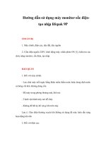
3.2 LCD
0000001
VA
HAR
90°15’15”
190°15’15”
TITL HOLD
The LCD is divided into four lines:
The first line----Instrument Number.
Initialization has been completed in the
factory of the instrument, can not be
changed.
The second line----vertical angle. XXX°
XX' XX" said the angle of the " degree
every minute units; Display for the GON
unit angle XXX.XXXX g; show for
XX.XXXX% slope.
The third line----horizontal angle. The
lower right corner of the word "R" for
15
theright corner of the mode, increased
clockwise rotation instrument angle;
upper right corner of the word "left"
means
Left
angle
mode,
counterclockwise rotation Instruments
will cause angle increase.
The fourth line---Electricity flag;
Other “Direction”, “Point”, “Switch”,
“Compensation”, ”lock” logo will display
with the corresponding function on.
16
4.Parameter settings
The instrument can set a number of
systemparameters and they are automatically
saved when the set is completed.
In the off state, press the【L/R】+【0 SET
】 key, then press the power button boot, you can
enter the system parameter setting mode.
0000001
0001000
001
On the screen of display 10 digit is either
"0",or "1", each figure or two figures represent
the meaning below.
Flashing digital can change.【L/R】 keys
move left;【V/%】key is moved to the right;
【0 SET】 key to switch parameters between 0
and 1.
After Setting the parameters, you can click
the 【 】key to shutdown, when reboot the
17
parameters work.
Parameters described in the following table:
18
5.Preparing for measurement
5.1 Instrument placement, centering and
leveling
Instrument mounted on a tripod, precise
leveling and alignment to ensure the precision of
the measurement results.
5.1.1 Plumb bob on leveling
1. Set up the tripod
Setup the tripod first: extend the extension
legs to suitable lengths and tighten the screws
on the mid sections. Make sure the legs are
spaced at equal intervals and the head is
approximately level. Set the tripod so that the
head is positioned over the surveying point.
Make sure the tripod -11-shoes are firmly
fixed in the ground.
19
2. Mount the instrument on the tripod head
Mount the instrument on the tripod head.
Supporting it with one hand, tighten the
centering screw on the bottom of the unit to
make sure it is secured to the tripod.
3. Centering and Leveling-Up
1. Position tripod legs so that the plummet is
aimed to the ground mark point. Turn the
focusing ring of the optical plummet to focus.
2. Turn three foot screws of the tribrach till the
center of reticle exactly coincides with the
surveying point in any position.
3. Move the tripod legs to centre the circular
level. The instrument is now roughly leveled-up.
4. Center the bubble in the circular level.
(1).
20
(2).
5. Center the surveying point again
Loosen the centering screw slightly. Looking
through the optical plummet eyepiece, slide
the instrument over the tripod head until the
21
surveying point is exactly centered in the
reticle. Re-tighten the centering screw
securely.
6. Check again to make sure the bubble in the
plate level is centered. If not, repeat procedure4.
5.1.2
Use the plummet for centering
1. Erecting a tripod
Setup the tripod first: extend the extension
legs to suitable lengths and tighten the screws
on the mid sections. Make sure the legs are
spaced at equal intervals and the head is
approximately level. Set the tripod so that the
head is positioned over the surveying point.
Make sure the tripod -11-shoes are firmly
fixed in the ground.
2. Mounting and centering
Mount the instrument on the tripod head.
Tighten the central connecting screw. Turn on
22
the instrument, Pres 【
】 to open
“Direction” light (Only for laser theodolite),
Press 【 】again to open laser “Point”, we
can see the red laser to the ground out from
the base down. Through the laser we can
adjust the position of the tripod point
observation. So that the next point roughly
aims at the station, make all three legs are
fixed on the ground. Adjust the instrument
three foot spiral to the point precisely to the
measurement site.
3. Do centering and leveling work again refers to
chapter 5.1.1 step 3 to step 5.
5.2 Telescope eyepiece adjustment and
target sighting
Eyepiece adjustment
1. Remove the telescope mirror cover.
2. Pointing to the sky through the telescope,
adjusting the eyepiece knob, the most clear
reticle crosshairs.
23
Object Sighting
1. Sight to the target with the crude sight.
2. Adjust the telescope focusing knob until the
object can been seeing clearly.
3. Tighten the horizontal and vertical brake knob,
fine-tune the two micro knob to accurately
sight the center of the crosshair to target,
move eye up and down for slightly observe,
if the relative shift between the two images of
the target with the crosshairs, then fine-tune
the telescope focusing knob until the two
images clear and relatively stationary ended
Clockwise rotation of the focusing knob to
closer to the target. Rotate counterclockwise
for contrary.
If step (3) is not adjusted well, the parallax
will distort the relationship of the target with
the reticle center, then leading to the
observation error.
Micro knob according to precise target for a
final time, should keep the knob clockwise. If
24
the rotation is too far, we’d better return and
re-sighting knob rotates clockwise.
Even if the eventuality vertical angle, we still
recommend to sight the target as far as
possible with the position of the center of the
crosshairs.
5.3 Switch On and Off
Switch On
Operation: Click【 】button to boot, after
boot it will display the surveying interface.
Switch Off
Operation: Press 【 】 for 3 seconds, See
on the screen as shown below with the word
"0.FF", you can release the button, the
instrument is turned off.
0000001
VA
HAR
0. F F
190°15’15”
TILT
25