Cisco IOS IPsec Accounting with Cisco IOS NetFlow _ www.bit.ly/taiho123
Bạn đang xem bản rút gọn của tài liệu. Xem và tải ngay bản đầy đủ của tài liệu tại đây (260.3 KB, 32 trang )
WHITE PAPER
CISCO IOS IPsec ACCOUNTING
WITH CISCO IOS NETFLOW
INTRODUCTION
Cisco IOS® NetFlow is the primary denial of service (DoS) identification, accounting, and
analysis technology for IP networks at Cisco and in the networking industry. Cisco IOS
NetFlow provides valuable information about network users, applications usage, timing,
and traffic direction on the network. Cisco is a leader in IP traffic flow technology and
invented Cisco IOS NetFlow.
Cisco IOS IPsec Network Security
Cisco IOS IPsec provides security for transmission of sensitive information over unprotected
networks (ie: Internet). IPsec acts as the network layer by protecting and authenticating IP
packets between participating IPsec devices (“peers”), such as Cisco routers.
This document will discuss how Cisco IOS NetFlow can be leveraged to provide accounting
information in an IPsec tunneling network topology.
For more information please visit:
• Cisco IOS NetFlow:
/>• Cisco IOS IPsec:
/>CISCO IOS NETFLOW OPERATION
Cisco IOS NetFlow provides a detailed record of the traffic on a network. Traffic records are
produced in a summarized and concise form. The flow information can be used for a variety
of purposes including accounting, billing, network planning, traffic engineering, and user/
application monitoring.
Cisco IOS NetFlow keeps a continuous track of packets and categorizes them by IP flows.
Each time Cisco IOS NetFlow detects a packet belonging to a new IP flow it creates a new
entry in the Cisco IOS NetFlow cache and starts a timer for the following events:
• Creation of the flow
• Arrival of the most recent packet belonging to that flow
If a flow does not have packets appearing for a preconfigured amount of time, then it has
“expired”. The default expiration time is fifteen seconds. As flows “expire” on the router,
they are removed from the live Cisco IOS NetFlow cache and exported in the Cisco IOS
Cisco Systems, Inc.
All contents are Copyright © 1992–2004 Cisco Systems, Inc. All rights reserved. Important Notices and Privacy Statement.
Page 1 of 32
NetFlow User Datagram Protocol (UDP) export packets to the
If two packets have the same entries for all seven fields, then they
collector, which then files, filters, and aggregates the data per the
belong to the same flow.
customers’ specifications.
The router maintains a live Cisco IOS NetFlow cache to track the
Cisco IOS NetFlow classifies packets by the way of flows.
current flows. Once those current flows expire, the flows are
Traditionally, and for the purposes of this document, Cisco IOS
removed from the Cisco IOS NetFlow cache to be exported to the
NetFlow flow is defined by seven key fields:
collector. The collector is an application that runs on a UNIX,
• Source IP
Linux, Window NT, or HP-UX server for the purposes of storing,
filtering, aggregating, and compressing the Cisco IOS NetFlow flow
• Destination IP
records.
• Source Port
Figure 1 shows the output of Cisco IOS NetFlow, which was
• Destination Port
produced by the “show ip cache flow” command:
• Protocol
• Type of service (ToS) byte
• Input Sub-interface
Figure 1
Sample Cisco IOS NetFlow Output
Line
7200-netflow#sh ip cache flow
1
IP packet size distribution (1693 total packets):
2
1-32
64
96
128
160
192
224
256
288
320
352
384
416
448
480
3
.000
.190
.190
.615
.000
.000
.000
.000
.000
.000
.000
.000
.000
.000
.000
4
512
544
576
1024
1536
2048
2560
3072
3584
4096
4608
5
.000
.000
.003
.000
.000
.000
.000
.000
.000
.000
.000
6
IP Flow Switching Cache, 4456704 bytes
7
2 active, 65534 inactive, 7 added
8
120 ager polls, 0 flow alloc failures
9
Active flows timeout in 30 minutes
10
Inactive flows timeout in 15 seconds
11
last clearing of statistics 00:03:18
12
Protocol
Total
Flows
Packets
Bytes
Packets
Active (Sec)
Idle (Sec)
13
-----
Flows
/Sec
/Flow
/Pkt
/Sec
/Flow
/Flow
14
TCP-Telnet
3
0.0
12
106
0.1
4.2
15.8
15
ICMP
2
0.0
500
100
5.2
2.6
15.4
16
Total:
5
0.0
207
100
5.4
3.6
15.6
17
SrcIf
SrcIPaddress
DstIf
DstIPaddress
Pr
SrcP
DstP
Pkts
18
Se3/0.16
10.1.10.1
Fa4/0
192.168.10.1
01
0000
0800
650
19
Se3/0.16
10.1.10.1
Fa4/0
192.168.10.1
06
0017
2AFF
6
The first portion of output lines, one through five, is the packet size
Lines six through eight describe the parameters assigned to Cisco
distribution, which provides information about what percentage of
IOS NetFlow itself. The default number of flows that can be cached
packets of each size has passed through this router. This information
by Cisco IOS NetFlow is 65536. In this case, two of these cache
can be very useful for network troubleshooting, traffic engineering,
entries were in use, and only 65534 cache entries were available for
and capacity planning.
new flows.
Cisco Systems, Inc.
All contents are Copyright © 1992–2004 Cisco Systems, Inc. All rights reserved. Important Notices and Privacy Statement.
Page 2 of 32
Lines nine through eleven show how long a particular flow will stay in the cache. In this example, if there has been
no activity on a flow for fifteen seconds, the entry would be purged from the cache. Additionally, if an entry has been
in the cache for thirty minutes, and at least one packet per fifteen seconds was there, then it is purged and a new flow
entry is created. Connection-oriented entries, such as telnet or File Transfer Protocol (FTP), are purged as soon as
the session is closed, which is based on a RST or FIN TCP Flag.
Lines twelve through sixteen provide a breakdown of flows by protocol. This is an ideal tool for the network
administrator, because it provides traffic distribution by type. This information can be used very effectively in
application monitoring.
Lines seventeen through nineteen show the actual Cisco IOS NetFlow cache entries. This portion of the Cisco IOS
NetFlow output will be referred as the ‘flow information table’ and will be the focus of the subsequent sections later
in this document.
The field titles have the following definitions:
• SrcIf—Source Sub-interface
• SrcIP—Source IP address
• DstIf—Destination Sub-interface
• DstIP – Destination IP address
• Pr—IP Protocol
• SrcP—Source Port number
• DstP—Destination Port number
• Pkts—Number of packets for this flow
For purposes of clarity and brevity, only selected portions of router configurations and router console output will
be displayed in the remainder of this document. For complete configurations and console output please refer to the
appendices.
For the purposes of this document, any data will not be exported outside of the router; therefore, flow information
will be examined prior to expiration of the router’s Cisco IOS NetFlow live cache.
IPsec NETWORK SECURITY OPERATION
IPsec combines the aforementioned security technologies into a complete system that provides confidentiality,
integrity, and authenticity of IP datagrams. IPsec refers to several related protocols as defined in the new Request
for Comments (RFC) 2401-2411 and 2451.The original IPsec RFCs 1825-1829 are now obsolete. These standards
include:
• IP Security Protocol proper:
– Defines the information to be added to an IP packet to enable confidentiality, integrity, and authenticity
controls
– Defines how to encrypt the packet data
• Internet Key Exchange (IKE):
– Negotiates the security association between two entities
– Exchanges key material
Cisco Systems, Inc.
All contents are Copyright © 1992–2004 Cisco Systems, Inc. All rights reserved. Important Notices and Privacy Statement.
Page 3 of 32
– Uses port 500 with User Datagram Protocol(UDP) protocol
– Used during the IPsec tunnel establishment
IPsec Encapsulation
IPsec has two methods of encapsulation:
• IPsec Tunnel mode
• Generic Routing Encapsulation (GRE) tunnel mode
Each differs in their application and in the amount of overhead added to the passenger packet.
IPsec Tunnel Mode
IPsec Tunnel Mode encapsulates and protects an entire IP packet. Because IPsec tunnel mode encapsulates or hides
the IP header of the packet, a new IP header must be added for the packet to be successfully forwarded. The
encrypting routers themselves own the IP addresses used in these new headers. Tunnel mode may be employed with
Encapsulating Security Payload (ESP) and/or Authentication Header. Using tunnel mode results in additional packet
expansion of approximately 20 bytes associated with the new IP header. Tunnel mode expansion of the IP packet is
depicted in Figure 2.
Figure 2
IPsec Tunnel Mode Encapsulation
New IP HDR
IPsec HDR
IP HDR
Data
IP HDR
Data
To Be Protected
GRE Transport Mode
GRE Transport mode is recommended to be used only when deploying GRE tunnel for the Virtual Private
Network (VPN) traffic. GRE Transport mode inserts an IPsec header between the IP header and the GRE Header.
In this case, transport mode saves an additional IP header, which results in less packet expansion. Transport mode
can be deployed with ESP and/or Authentication Header. Specifying transport mode allows the router to negotiate
with the remote peer whether to use transport or tunnel mode. Transport mode expansion of the IP packet with GRE
encapsulation is depicted in Figure 3.
Cisco Systems, Inc.
All contents are Copyright © 1992–2004 Cisco Systems, Inc. All rights reserved. Important Notices and Privacy Statement.
Page 4 of 32
Figure 3
IPsec Using GRE Tunnel Mode Encapsulation
New IP HDR
IPsec HDR
GRE HDR
IP HDR
Data
IP HDR
Data
To Be Protected
IPsec is using one type of IPsec encapsulation modes: IPsec Tunnel mode or GRE transport mode. The IPsec Header
encapsulates the outer header, so the type of encapsulation is not visible from Cisco IOS NetFlow perspective.
IPsec Headers
IPsec defines a new set of headers to be added to IP datagrams. These new headers are placed after the outer IP header
and provide information for securing the payload of the IP packet as follows:
• Authentication Header—this header, when added to an IP datagram, ensures the integrity and authenticity of the
data, including the invariant fields in the outer IP header. Authentication Header is identified as IP protocol 51
(33 in Hex).
• Encapsulating Security Payload (ESP)—this header, when added to an IP datagram, protects the confidentiality,
integrity, and authenticity of the data. If ESP is used to validate data integrity, it does not include the invariant
fields in the IP header. ESP is always used as the outer encapsulation in the IPsec header. ESP header is identified
as IP protocol 50 (32 in Hex).
IPsec Header may be employed with ESP and/or Authentication Header. While Authentication Header and ESP can
be used either independently or together, one of them will suffice for most applications.
TOPOLOGY
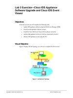
Figure 4 shows the topology used in this configuration. In the following tests an IPsec tunnel between Cisco 3600-4
and 7200-2 Series Routers has been configured. Then Cisco IOS Software Service Assurance Agent (SAA) has been
used to generate packets from the Cisco 7200-3 Series Router to the Cisco 3600-6 Series Multiservice Hardware.
As mentioned earlier, only the live Cisco IOS NetFlow cache will be examined, records on the collector will not be
examined. By default Cisco IOS NetFlow has aging timers of fifteen seconds. The flow has ‘expired’ and is removed
from the live Cisco IOS NetFlow cache if it has a period of fifteen or more seconds when no packets belonging to it
are received. Therefore, the Cisco IOS SAA packets generated for this document will have a frequency of greater than
fifteen seconds to ensure that there is a constant flow record in the live Cisco IOS NetFlow cache to look at via
command-line interface (CLI). For details on the Cisco IOS SAA configuration, please check Appendix A. For this
document, all the routers are running Cisco IOS Software Release 12.3.
Cisco Systems, Inc.
All contents are Copyright © 1992–2004 Cisco Systems, Inc. All rights reserved. Important Notices and Privacy Statement.
Page 5 of 32
Figure 4
Test Bed Topology
NetFlow Enabled Here
Test 3
7200-3
POS 1/0
7200-2
POS 4/0
FE 2/0 FE 1/0
3600-4
FE 1/1
FE 1/0
3600-6
Eth 0/1
2600-5
Eth 0/0
Tunnel
.3 20.0.10.0
.2
.2
90.0.0.0 .4
.4 180.0.0.0
.6
.6
120.0.40.0
.5
Test Packets
Test 1
Test 2
NetFlow Enabled Here
This test and document were based on the Cisco IOS Software based hardware Cisco 2600, 3600, and 7200 Series
Routers. The same results would be received if Cisco IOS NetFlow is run on any other Cisco IOS Software based
hardware, such as the Cisco 800, 1600, 2500, 7300 (non-PxF based processors), and 7400 Series Routers,
Cisco 3700 Series Multiservice Access Router, and Cisco Catalyst®4500 Series Switch. Interface type does not change
Cisco IOS NetFlow behavior on this hardware. The results that were received on the FastEthernet, POS, and Ethernet
interfaces were used and can substitute any of the other interfaces available on that hardware.
TEST BED ANALYSIS
The topology in Figure 4 shows three different test points on the network along the path of the IPsec traffic:
• Test 1 is the edge interface of the VPN network. Cisco IOS NetFlow counts for unencrypted traffic at this entry
point.
• Test 2 is the encrypted interface of the VPN network. At this point Cisco IOS NetFlow counts for the IPsec traffic
in addition to the rest of the traffic that is transmitted unencrypted.
• Test 3 is a network interface along the path between the IPsec peers.
For the purposes of this test Cisco IOS NetFlow will be studied at the Edge interface, the Encryption interface, and
a network interface that is forwarding the IPsec traffic.
ENABLING CISCO IOS NETFLOW ON INTERFACE
To enable Cisco IOS NetFlow on an interface (ie: FastEthernet 2/0 on Cisco 7200-2 Series Router), the following
steps can be used:
7200-2# show running-config
!
interface FastEthernet 2/0
ip route-cache flow
!
With the exception of specific egress Cisco IOS NetFlow features, Cisco IOS NetFlow is an ingress technology. Since
standard ingress Cisco IOS NetFlow has been enabled on the interface, the flows tracked in the cache are going to
be from packets traveling inbound to this interface only.
Cisco Systems, Inc.
All contents are Copyright © 1992–2004 Cisco Systems, Inc. All rights reserved. Important Notices and Privacy Statement.
Page 6 of 32
THE TESTS
To understand the Cisco IOS NetFlow data collection of an IPsec traffic, Cisco IOS NetFlow will be examined
on each of the edges and encrypted on network interfaces of an IPsec path (as shown in the topology in
Figure 4).The tests are:
Test 1: POS 4/0 interface of Cisco 7200-2 (tunnel head) Series Router
Test 2: FastEthernet 2/0 interface of Cisco 7200-2 (tunnel head) Series Router
Test 3: FastEthernet 1/0 interface of Cisco3600-4 (tunnel midpoint) Series Multiservice Hardware
TEST 1—CISCO IOS NETFLOW ON FASTETHERNET 1/0 INTERFACE OF CISCO7200-2 (TUNNEL HEAD)
SERIES ROUTER
At this interface the traffic is sent and received unencrypted. Cisco IOS NetFlow enabled on this interface counts for
inbound traffic on interface POS 4/0. The following results on the Cisco 7200-2 Series Router show traffic received
from the Cisco 7200-3 Series Router, which is sending Cisco IOS SAA packets.
7200-2# show ip cache flow | begin SrcIf
SrcIf
SrcIPaddress DstIf
DstIPaddress
Pr SrcP
DstP
Pkts
PO4/0
20.0.10.3
Fa2/0
120.0.40.5
11 FDEB 07AF
12
PO4/0
20.0.10.3
Fa2/0
120.0.40.5
11 FDEB 07AF
14
PO4/0
20.0.10.3
Null
224.0.0.10
58 0000 0000
296
PO4/0
20.0.10.3
Fa2/0
120.0.40.5
11 FDEB FE1B
26
PO4/0
20.0.10.3
Fa2/0
120.0.40.5
11 FDEB FE1C
48
Note: The flow entries protocol and port numbers are displayed in Hex (ie: Cisco IOS SAA traffic uses UDP protocol
17 or 11 in Hexadecimal; Enhanced Interior Gateway Routing Protocol (EIGRP) uses UDP protocol 88 or 58 in
Hexadecimal). All the test traffic from Cisco IOS SAA is unencrypted at the entry to the IPsec network. Since the
‘flow information table’ portion of the “show ip cache flow” command starts later, the output modifier “| begin”
is used with the “show” command to begin at the start of the table.
The verbose command elaborates on the last part of Cisco IOS NetFlow cache displaying valuable additional flow
information:
7200-2# show ip cache verbose flow | begin SrcIf
SrcIf
SrcIPaddress
DstIf
DstIPaddress
Pr TOS Flgs
Port Msk AS
Port Msk AS
NextHop
B/Pk
Active
PO4/0
20.0.10.3
Fa2/0
120.0.40.5
11 40 10
FDEB /24 0
07AF /8 0
90.0.0.4
80
130.0
PO4/0
20.0.10.3
Fa2/0
120.0.40.5
11 80 10
FDEB /24 0
07AF /8 0
90.0.0.4
80
140.0
PO4/0
20.0.10.3
Null
224.0.0.10
58 C0 10
0000 /24 0
0000 /24 0
0.0.0.0
60
1380.4
IPM:
0
0
Pkts
14
16
299
Cisco Systems, Inc.
All contents are Copyright © 1992–2004 Cisco Systems, Inc. All rights reserved. Important Notices and Privacy Statement.
Page 7 of 32
PO4/0
20.0.10.3
Fa2/0
120.0.40.5
11 80 10
FDEB /24 0
FE1B /8 0
90.0.0.4
60
135.0
PO4/0
20.0.10.3
Fa2/0
120.0.40.5
11 40 10
FDEB /24 0
FE1C /8 0
90.0.0.4
60
130.0
30
56
7200-2#
All of the fields that display the flows are wrapped to two lines. ToS byte (in Hex) is included in this output. If type
of service (ToS) byte is added, the summarized output will look like this:
SrcIf
SrcIP
DstIf
DstIP
Prot
SrcP
DstP
ToS
Pkts
PO4/0
20.0.10.3
Fa2/0
120.0.40.5
11
FDEB
07AF
40
12
PO4/0
20.0.10.3
Fa2/0
120.0.40.5
11
FDEB
07AF
80
14
PO4/0
20.0.10.3
Null
224.0.0.10
58
0000
0000
C0
296
PO4/0
20.0.10.3
Fa2/0
120.0.40.5
11
FDEB
FE1B
80
26
PO4/0
20.0.10.3
Fa2/0
120.0.40.5
11
FDEB
FE1C
40
48
Since Cisco IOS NetFlow is an ingress technology, only the flows coming into interface POS 4/0 will be studied.
The last two flows on the bottom represent the two Cisco IOS SAA operations configured.
The middle flow reflect Enhanced EIGRP packets and the destination IP of 224.0.0.10, which is a multicast address
used by EIGRP to distribute routing information. The “Null” destination interface will be seen for all those packets
that are to be dropped by something like an access-list or multicast traffic in this case. Note that Cisco IOS NetFlow
now has a multicast support feature via Cisco IOS NetFlow version 9.
The first two flows represent the control messages for the two Cisco IOS SAA operations configured. By design
Cisco IOS SAA sends an initial control message to notify the destination of the upcoming Cisco IOS SAA operation
traffic and the appropriate port number. Cisco IOS SAA control messages are always sent on port 1967 (07AF in
Hexadecimal).
For understanding the debug messages on this Cisco 7200-2 Series Router, check Appendix B.
Enabling Cisco IOS NetFlow on the non-IPsec interface of an IPsec enabled router will allow seeing all the packets
coming into the router via that interface prior to encryption.
TEST 2—CISCO IOS NETFLOW ON FASTETHERNET 2/0 INTERFACE OF CISCO 7200-2 (TUNNEL HEAD)
SERIES ROUTER
With Cisco IOS NetFlow enabled on interface FastEthernet 2/0, Cisco IOS NetFlow counts traffic entering that
interface. The following is the output of the Cisco IOS NetFlow cache information on the router:
7200-2# show ip cache flow | begin SrcIf
SrcIf
SrcIPaddress
DstIf
DstIPaddress
Pr SrcP DstP
Pkts
Fa2/0
120.0.40.5
PO4/0
20.0.10.3
11 07AF FDEB
9
Fa2/0
120.0.40.5
PO4/0
20.0.10.3
11 07AF FDEB
10
Fa2/0
90.0.0.4
Null
224.0.0.10
58 0000 0000
260
Cisco Systems, Inc.
All contents are Copyright © 1992–2004 Cisco Systems, Inc. All rights reserved. Important Notices and Privacy Statement.
Page 8 of 32
Fa2/0
120.0.40.5
PO4/0
20.0.10.3
11 FE1B FDEB
20
Fa2/0
120.0.40.5
PO4/0
20.0.10.3
11 FE1C FDEB
36
Fa2/0
180.0.0.6
Local
90.0.0.2
32 F295 7AFB
75
Fa2/0
180.0.0.6
Local
90.0.0.2
11 01F4 01F4
2
The first, second, forth, and fifth flows are the Cisco IOS SAA control messages and operations. These Cisco IOS
SAA packets, which are being accounted for, are on their return journey However, note, that the destination, source
numbers for IP address and port numbers have been reversed compare to the flows in Test 1.
The third flow with the Null destination interface reflects the EIGRP update packets with an IP protocol of 88 (58 in
Hexadecimal).
The IPsec configuration on Cisco 7200-2 Series Router, shown in appendix C, utilizes esp-3des encapsulation. The
final flow with protocol 50 (32 Hexadecimal) accounts for the ESP Header, which encapsulate the IPsec packets. To
get the packet count for Ipsec tunnel (75),count the packet for the Cisco IOS SAA packets in the first, second, third,
and forth flows (9 + 10 + 36 + 20).This means that network traffic, in this case Cisco IOS SAA traffic, in the IPsec
tunnel has been accounted for and broken out into separate flows outside of the tunnel.
The protocol 17 is for UDP (11 in Hexadecimal) with port 500 (01F4 in Hexadecimal) for Internet Key Exchange
protocol received from the remote IPsec peer. The IKE traffic is sent less frequently between the IPsec peers; therefore,
the show command on the router may or may not show a count. Despite of this the Cisco IOS NetFlow information
in regards to the IKE activities is reported to the collector. There is another alternative to see this exchange in the live
Cisco IOS NetFlow cache: via the “show ip cache flow”. To do this the default timeout value for Cisco IOS NetFlow
needed to be increased.
Using verbose command for the ToS byte:
7200-2# show ip cache verbose flow | begin SrcIf
SrcIf
SrcIPaddress
DstIf
DstIPaddress
Pr TOS Flgs
Port Msk AS
Port Msk AS
NextHop
B/Pk
Active
Fa2/0
120.0.40.5
PO4/0
20.0.10.3
11 40 10
10
FDEB /24 0
20.0.10.0
36
90.0
PO4/0
20.0.10.3
11 80 10
11
FDEB /24 0
20.0.10.0
36
95.0
Null
224.0.0.10
58 C0 10
263
0000 /24 0
0.0.0.0
60
1207.2
07AF /8 0
Fa2/0
120.0.40.5
07AF /8 0
Fa2/0
90.0.0.4
0000 /24 0
Pkts
IPM:
0
0
Fa2/0
120.0.40.5
PO4/0
20.0.10.3
11 80 10
22
FDEB /24 0
20.0.10.0
60
95.0
PO4/0
20.0.10.3
11 40 10
40
FDEB /24 0
20.0.10.0
60
90.0
Local
90.0.0.2
32 00 10
83
7AFB /0 0
0.0.0.0
93
100.0
FE1B /8 0
Fa2/0
120.0.40.5
FE1C /8 0
Fa2/0
F295 /16 0
180.0.0.6
7200-2#
Cisco Systems, Inc.
All contents are Copyright © 1992–2004 Cisco Systems, Inc. All rights reserved. Important Notices and Privacy Statement.
Page 9 of 32
Adding the ToS byte and B/Pk (Bytes per packet) and changing the hex entries to decimal:
SrcIf
SrcIP
DstIf
DstIP
Prot
SrcP
DstP
ToS
Pkts
B/Pk
Fa2/0
120.0.40.5
PO4/0
20.0.10.3
17
1967
65003
64
9
36
Fa2/0
120.0.40.5
PO4/0
20.0.10.3
17
1967
65003
128
10
36
Fa2/0
90.0.0.4
Null
224.0.0.10
88
0000
0000
192
260
60
Fa2/0
120.0.40.5
PO4/0
20.0.10.3
17
65051
65003
128
20
60
Fa2/0
120.0.40.5
PO4/0
20.0.10.3
17
65052
65003
64
36
60
Fa2/0
180.0.0.6
Local
90.0.0.2
50
62101
1967
00
75
93
The non-encrypted Cisco IOS SAA flows have a total of seventy five packets and 4,044 bytes, which makes for an
average of ~54 bytes per packet. In contrast, the encrypted flows also have seventy five packets with an average of
ninety three bytes per packet. These additional bytes in each packet account for the New IP header and IPsec header,
as shown in the earlier diagram.
To verify the IPsec tunnel configuration and packet forwarding use the following command:
7200-2#show crypto ipsec sa
interface: FastEthernet2/0
Crypto map tag: arsenal, local addr. 90.0.0.2
protected vrf:
local ident (addr/mask/prot/port): (20.0.10.0/255.255.255.0/0/0)
remote ident (addr/mask/prot/port): (120.0.40.0/255.255.255.0/0/0)
current_peer: 180.0.0.6:500
PERMIT, flags={origin_is_acl,}
#pkts encaps: 3248, #pkts encrypt: 3248, #pkts digest 0
#pkts decaps: 3248, #pkts decrypt: 3248, #pkts verify 0
#pkts compressed: 0, #pkts decompressed: 0
#pkts not compressed: 0, #pkts compr. failed: 0
#pkts not decompressed: 0, #pkts decompress failed: 0
#send errors 2, #recv errors 0
From this command the total number of only encrypted packets can be seen.
In summary, enabling Cisco IOS NetFlow on the encrypting interface provides with additional flow information not
only the packets in the IPsec tunnel, but also the packets broken up into separate flows outside of the tunnel.
TEST 3—CISCO IOS NETFLOW ON FASTETHERNET 1/0 INTERFACE OF CISCO 3600-4 (TUNNEL MIDPOINT)
SERIES MULTISERVICE HARDWARE
The following can be seen from the Cisco IOS NetFlow cache on the tunnel midpoint:
3600-4# show ip cache flow | begin SrcIf
SrcIf
SrcIPaddress
DstIf
DstIPaddress
Pr SrcP DstP
Pkts
Fa1/0
90.0.0.2
Null
224.0.0.10
58 0000 0000
139
Fa1/0
90.0.0.2
Fa1/1
180.0.0.6
32 3265 B7C9
59
Fa1/0
90.0.0.2
Fa1/1
180.0.0.6
11 01F4 01F4
2
Cisco Systems, Inc.
All contents are Copyright © 1992–2004 Cisco Systems, Inc. All rights reserved. Important Notices and Privacy Statement.
Page 10 of 32
The previous command shows the Cisco IOS NetFlow cache on output of the middle router. The first protocol 88
(58 in Hexadecimal) is for EIGRP protocol. Protocol 50 (32 in Hexadecimal) is for the actual IPsec tunnel traffic.
The UDP protocol 17 (11 in Hexadecimal), with port 500 (01F4 in Hexadecimal) in both directions, is for the
Internet Key Exchange (IKE) protocol traffic between the IPsec peers. As mentioned earlier, the IKE traffic is sent less
frequently between the IPsec peers, so the show command on the router may or may not show a count. In any case,
the Cisco IOS NetFlow information in regards to the IKE activities is reported to the collector.
To add the ToS byte information verbose is used:
3600-4# show ip cache verbose flow | begin SrcIf
SrcIf
SrcIPaddress
Port Msk AS
Fa1/0
90.0.0.2
0000 /24 0
DstIf
DstIPaddress
Pr TOS Flgs
Pkts
Port Msk AS
NextHop
B/Pk
Active
Null
224.0.0.10
58 C0 10
140
0000 /24 0
0.0.0.0
60
644.9
IPM:
0
0
Fa1/0
90.0.0.2
Fa1/1
180.0.0.6
32 00 10
67
B7C9 /24 0
180.0.0.6
106
80.0
3265 /24 0
3600-4#
By adding the ToS byte and translating the protocol, ports, and ToS byte from Hex to decimal the following can be
received:
SrcIf
SrcIP
DstIf
DstIP
Prot
SrcP
DstP
ToS
Pkts
Fa1/0
90.0.0.2
Null
224.0.0.10
88
0000
0000
192
139
Fa1/0
90.0.0.2
Fa1/1
180.0.0.6
50
12901
47049
00
59
The last flow is the IPsec tunnel. Notice that, as expected, the IPsec packets protocol, port numbers, and ToS byte
have changed from the Cisco IOS SAA packets enclosed in the payloads. The destination IP address is the end of IPsec
tunnel.
The top flow represents the incoming EIGRP updates from the neighboring Cisco 7200-2 Series Router. These EIGRP
updates are underlined in the debug below:
Warning: use a “debug ip packet detail” command only when the traffic on the router is low, otherwise this command
can crash the router.
3600-4# debug ip packet detail
IP packet debugging is on (detailed)
3600-4#
*Mar 1 12:29:53: IP: s=180.0.0.4 (local), d=224.0.0.10 (FastEthernet1/1), len 60, sending broad/multicast, proto=88
*Mar 1 12:29:54: IP: s=90.0.0.2 (FastEthernet1/0), d=224.0.0.10, len 60, rcvd 2, proto=88
*Mar 1 12:29:54: IP: s=0.0.0.0 (Ethernet0/0), d=255.255.255.255, len 604, rcvd 2
*Mar 1 12:29:54:
UDP src=68, dst=67
Cisco Systems, Inc.
All contents are Copyright © 1992–2004 Cisco Systems, Inc. All rights reserved. Important Notices and Privacy Statement.
Page 11 of 32
*Mar 1 12:29:55: IP: s=180.0.0.6 (FastEthernet1/1), d=224.0.0.10, len 60, rcvd 2, proto=88
*Mar 1 12:29:55: IP: s=90.0.0.4 (local), d=224.0.0.10 (FastEthernet1/0), len 60, sending broad/multicast, proto=88
*Mar 1 12:29:56: IP: s=10.4.23.90 (Ethernet0/0), d=10.0.227.4 (Ethernet0/0), len 76, rcvd 3
*Mar 1 12:29:56:
UDP src=123, dst=123
*Mar 1 12:29:56: IP: s=10.0.227.4 (local), d=10.4.23.90 (Ethernet0/0), len 76,sending
*Mar 1 12:29:56:
UDP src=123, dst=123
*Mar 1 12:29:56: IP: s=0.0.0.0 (Ethernet0/0), d=255.255.255.255, len 604, rcvd 2
*Mar 1 12:29:56:
UDP src=68, dst=67
*Mar 1 12:29:57: IP: s=180.0.0.4 (local), d=224.0.0.10 (FastEthernet1/1), len 60, sending broad/multicast, proto=88
*Mar 1 12:29:58: IP: s=0.0.0.0 (Ethernet0/0), d=255.255.255.255, len 604, rcvd 2
*Mar 1 12:29:58:
UDP src=68, dst=67
*Mar 1 12:29:58: IP: s=90.0.0.2 (FastEthernet1/0), d=224.0.0.10, len 60, rcvd 2, proto=88
*Mar 1 12:30:00: IP: s=180.0.0.6 (FastEthernet1/1), d=224.0.0.10, len 60, rcvd 2, proto=88
*Mar 1 12:30:00: IP: s=90.0.0.4 (local), d=224.0.0.10 (FastEthernet1/0), len 60, sending broad/multicast, proto=88
*Mar 1 12:30:00: IP: s=0.0.0.0 (Ethernet0/0), d=255.255.255.255, len 604, rcvd 2
*Mar 1 12:30:00:
UDP src=68, dst=67
*Mar 1 12:30:02: IP: s=180.0.0.4 (local), d=224.0.0.10 (FastEthernet1/1), len 60, sending broad/multicast, proto=88
*Mar 1 12:30:02: IP: s=0.0.0.0 (Ethernet0/0), d=255.255.255.255, len 604, rcvd 2
*Mar 1 12:30:02:
UDP src=68, dst=67
*Mar 1 12:30:03: IP: s=90.0.0.2 (FastEthernet1/0), d=224.0.0.10, len 60, rcvd 2, proto=88
*Mar 1 12:30:04: IP: s=0.0.0.0 (Ethernet0/0), d=255.255.255.255, len 604, rcvd 2
*Mar 1 12:30:04:
UDP src=68, dst=67
3600-4# undebug all
All possible debugging has been turned off
3600-4#
Cisco IOS NetFlow accounts for the tunneled packets, while the debug does not pick them up. However, the packets
are accounted for encapsulated packets; and therefore, have different packet header fields (ie: protocol, port numbers,
ToS byte, and destination interface) than the original Cisco IOS SAA packets, which are encapsulated in the packet
payloads.
Cisco Systems, Inc.
All contents are Copyright © 1992–2004 Cisco Systems, Inc. All rights reserved. Important Notices and Privacy Statement.
Page 12 of 32
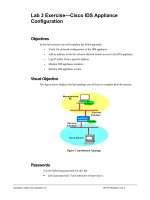
CONCLUSION
Figure 5
Summary of NetFlow in IPsec Topology
NetFlow Totals Tunnel
Packets Into One Flow
7200-3
POS 1/0
7200-2
3600-4
2600-5
3600-6
POS 4/0
FE 2/0 FE 1/0
FE 1/1 FE 1/0
Eth 0/1 Eth 0/0
Tunnel
20.0.10.0
90.0.0.0
.3
.4
.4 180.0.0.0
.5
.2
.6
.6 120.0.40.0
.2
Test Packets
NetFlow Accounts
for Packets Prior to
IPsec Tunnel
NetFlow Accounts for Both
The Tunnel and Post-Tunnel Flows
NetFlow Accounts
for Packets Prior to
IPsec Tunnel
The test has determined following conditions with Cisco IOS NetFlow enabled at these points:
• Outside facing, non-tunnel edge interfaces (Test 1) tracked pre-IPsec tunnel packets in flows. All packets were
accounted for in flows prior to encryption.
• Inside facing, head and tail encrypted tunnel interfaces (Test 2) tracked the flows in both pre and post tunneling.
This accounting allows tracking the overall number of packets in the tunnel and the individual flows separated
out prior to the tunneling. This clearly provides the most details of the Cisco IOS NetFlow options.
• Network midpoint tunnel interfaces (Test 3) tracked only summary of the tunneled packets in one individual flow.
Once packets are encrypted, it becomes impossible to see inside their payload, and the granularity seen in other
Cisco IOS NetFlow options is lost.
In conclusion, enabling the Cisco IOS NetFlow on the inside facing, head and tail tunnel encrypted interfaces (Test 2)
gave the most detailed information. If the user is looking for the most detailed flow information, then the head and
tail interfaces are the best positions to leverage the Cisco IOS NetFlow.
APPENDIX A CISCO IOS SAA CONFIGURATIONS
To bring up the tunnel Cisco IOS Service Assurance Agent (SAA) generation of traffic would be ideal. Configure the
destination (responder) first:
2600-5# show running-config | include responder
rtr responder
Cisco Systems, Inc.
All contents are Copyright © 1992–2004 Cisco Systems, Inc. All rights reserved. Important Notices and Privacy Statement.
Page 13 of 32
Two Cisco IOS SAA operations are configured:
7200-3# show running-config
!
rtr 1
type jitter dest-ipaddr 120.0.40.5 dest-port 65051 source-ipaddr 20.0.10.3 source-port
65003 num-packets 2
tos 128
frequency 10
rtr schedule 1 start-time 19:04:59 Feb 14
rtr 2
type jitter dest-ipaddr 120.0.40.5 dest-port 65052 source-ipaddr 20.0.10.3 source-port
65003 num-packets 4
tos 64
frequency 10
rtr schedule 2 start-time 19:05:00 Feb 14
!
This Cisco IOS SAA configuration will generate the following test packets:
1. Two packets every ten seconds with the following characteristics:
• Source IP 20.0.10.3
• Destination IP 120.0.40.5
• Source Port 65003
• Destination Port 65051
• ToS byte 128
2. Four packets every ten seconds with the following characteristics:
• Source IP 20.0.10.3
• Destination IP 120.0.40.5
• Source Port 65003
• Destination Port 65052
• ToS byte 64
The ToS byte and destination port are different only in numbers of packets being sent. In addition, each operation
sends a control message prior to the Cisco IOS SAA operation packets. Each control message sends one packet to the
responder to establish the port number that the operation packets will be sent to.
This Cisco IOS SAA configuration causes the Cisco IOS SAA sender to send the following traffic:
7200-2# show ip cache flow | begin SrcIf
SrcIf
SrcIPaddress
DstIf
DstIPaddress
Pr SrcP
DstP
Pkts
PO4/0
20.0.10.3
Fa2/0
120.0.40.5
11 FDEB 07AF
12
PO4/0
20.0.10.3
Fa2/0
120.0.40.5
11 FDEB 07AF
14
PO4/0
20.0.10.3
Fa2/0
120.0.40.5
11 FDEB FE1B
26
PO4/0
20.0.10.3
Fa2/0
120.0.40.5
11 FDEB FE1C
48
Cisco Systems, Inc.
All contents are Copyright © 1992–2004 Cisco Systems, Inc. All rights reserved. Important Notices and Privacy Statement.
Page 14 of 32
The top two flows are the Cisco IOS SAA control messages that are sent to the responder prior to each Cisco IOS
SAA operation begins. This tells the responder that Cisco IOS SAA packets are about to be sent to the router and
to pass the port number, etc… The Cisco IOS SAA control messages are sent to port 1967, but the other six key
Cisco IOS NetFlow fields (ie:SrcIf, SrcIP, DstIP, Prot, SrcP, and ToS) remain the same as the Cisco IOS SAA operation
packets that are about to follow. Those proceeding Cisco IOS SAA operation packets have a different destination
port; and therefore, create different flows. By pairing up the two Cisco IOS SAA operations the following can be get:
The control message is sent first:
SrcIf
SrcIP
DstIf
DstIP
Prot
SrcP
DstP
ToS
Pkts
PO4/0
20.0.10.3
Fa2/0
120.0.40.5
17
65003
1967
64
12
17
65003
65051
64
26
Followed by the Cisco IOS SAA operation packets:
PO4/0
20.0.10.3
Fa2/0
120.0.40.5
For the other Cisco IOS SAA operation the control message is sent:
SrcIf
SrcIP
DstIf
DstIP
Prot
SrcP
DstP
ToS
Pkts
PO4/0
20.0.10.3
Fa2/0
120.0.40.5
17
65003
1967
128
14
17
65003
65052
128
48
Correspondingly followed by the operation packets:
PO4/0
20.0.10.3
Fa2/0
120.0.40.5
APPENDIX B DEBUGS
From debug on Cisco 7200-2 Series Router the following output can be received:
Note: enable this “debug ip packet detail” command only on a router with a little packet activity otherwise it can
crash the router.
7200-2# conf t
Enter configuration commands, one per line. End with CNTL/Z.
7200-2(config)# logging console
7200-2(config)# end
7200-2# debug ip packet detail
IP packet debugging is on (detailed)
7200-2#
Feb 18 18:10:40: IP: s=90.0.0.2 (local), d=224.0.0.10 (FastEthernet2/0), len 60, sending broad/multicast, proto=88
Feb 18 18:10:43: IP: s=20.0.10.2 (local), d=224.0.0.10 (POS4/0), len 60, sending broad/multicast, proto=88
Feb 18 18:10:44: IP: s=90.0.0.4 (FastEthernet2/0), d=224.0.0.10, len 60, rcvd 2, proto=88
Feb 18 18:10:44: IP: s=20.0.10.3 (POS4/0), d=224.0.0.10, len 60, rcvd 2, proto=88
Cisco Systems, Inc.
All contents are Copyright © 1992–2004 Cisco Systems, Inc. All rights reserved. Important Notices and Privacy Statement.
Page 15 of 32
Feb 18 18:10:45: IP: s=90.0.0.2 (local), d=224.0.0.10 (FastEthernet2/0), len 60, sending broad/multicast, proto=88
Feb 18 18:10:46: IP: s=10.0.227.2 (local), d=10.0.227.4 (FastEthernet1/0), len 76, sending
Feb 18 18:10:46:
UDP src=123, dst=123
Feb 18 18:10:46: IP: s=10.0.227.4 (FastEthernet1/0), d=10.0.227.2 (FastEthernet1/0), len 76, rcvd 3
Feb 18 18:10:46:
UDP src=123, dst=123
Feb 18 18:10:48: IP: s=20.0.10.2 (local), d=224.0.0.10 (POS4/0), len 60, sending broad/multicast, proto=88
Feb 18 18:10:48: IP: s=20.0.10.3 (POS4/0), d=224.0.0.10, len 60, rcvd 2, proto=88
Feb 18 18:10:48: IP: s=90.0.0.4 (FastEthernet2/0), d=224.0.0.10, len 60, rcvd 2, proto=88
Feb 18 18:10:50: IP: s=90.0.0.2 (local), d=224.0.0.10 (FastEthernet2/0), len 60, sending broad/multicast, proto=88
Feb 18 18:10:52: IP: s=20.0.10.2 (local), d=224.0.0.10 (POS4/0), len 60, sending broad/multicast, proto=88
Feb 18 18:10:53: IP: s=20.0.10.3 (POS4/0), d=224.0.0.10, len 60, rcvd 2, proto=88
Feb 18 18:10:53: IP: s=90.0.0.4 (FastEthernet2/0), d=224.0.0.10, len 60, rcvd 2, proto=88
Feb 18 18:10:55: IP: s=90.0.0.2 (local), d=224.0.0.10 (FastEthernet2/0), len 60, sending broad/multicast, proto=88
Feb 18 18:10:57: IP: s=20.0.10.2 (local), d=224.0.0.10 (POS4/0), len 60, sending broad/multicast, proto=88
Feb 18 18:10:57: IP: s=20.0.10.3 (POS4/0), d=224.0.0.10, len 60, rcvd 2, proto=88
Feb 18 18:10:58: IP: s=90.0.0.4 (FastEthernet2/0), d=224.0.0.10, len 60, rcvd 2, proto=88
Feb 18 18:10:59: IP: s=90.0.0.2 (local), d=224.0.0.10 (FastEthernet2/0), len 60, sending broad/multicast, proto=88
7200-2# undebug all
All possible debugging has been turned off
7200-2#
In summary the following packets are being shown:
Every 4–5 seconds EIGRP updates incoming via POS 4/0 (these packets are being seen as one flow in the Cisco IOS
NetFlow cache):
Feb 18 18:10:44: IP: s=20.0.10.3 (POS4/0), d=224.0.0.10, len 60, rcvd 2, proto=88
The packets from this flow have been underlined in the debug output above.
Every 5 seconds EIGRP updates outgoing via POS 4/0:
Feb 18 18:10:43: IP: s=20.0.10.2 (local), d=224.0.0.10 (POS4/0), len 60, sending broad/multicast, proto=88
Every 4–5 seconds EIGRP updates incoming via Fast 2/0:
Feb 18 18:10:44: IP: s=90.0.0.4 (FastEthernet2/0), d=224.0.0.10, len 60, rcvd 2, proto=88
Every 5 seconds EIGRP updates outgoing via Fast 2/0:
Feb 18 18:10:40: IP: s=90.0.0.2 (local), d=224.0.0.10 (FastEthernet2/0), len 60, sending broad/multicast, proto=88
Cisco Systems, Inc.
All contents are Copyright © 1992–2004 Cisco Systems, Inc. All rights reserved. Important Notices and Privacy Statement.
Page 16 of 32
NTP request and reply:
Feb 18 18:10:46: IP: s=10.0.227.2 (local), d=10.0.227.4 (FastEthernet1/0), len 76, sending
Feb 18 18:10:46:
UDP src=123, dst=123
Feb 18 18:10:46: IP: s=10.0.227.4 (FastEthernet1/0), d=10.0.227.2 (FastEthernet1/0), len 76, rcvd 3
Feb 18 18:10:46:
UDP src=123, dst=123
The debug does not reflect the tunneled packets, so all the packets associated with encryption are not shown.
However, Cisco IOS NetFlow picks up and accounts for them.
Cisco Systems, Inc.
All contents are Copyright © 1992–2004 Cisco Systems, Inc. All rights reserved. Important Notices and Privacy Statement.
Page 17 of 32
APPENDIX C—ROUTER VERSIONS AND CONFIGURATIONS
Cisco 7200-3 Series Router
7200-3# show version
Cisco IOS Software, 7200 Software (C7200-JS-M), Version 12.3(4)T2, RELEASE SOFT
WARE (fc1)
TAC Support: />Copyright (c) 1986-2003 by Cisco Systems, Inc.
Compiled Thu 18-Dec-03 17:39 by dchih
ROM: System Bootstrap, Version 12.1(20000824:081033) [dbeazley-cosmos_e_LATEST 1
01], DEVELOPMENT SOFTWARE
BOOTLDR: 7200 Software (C7200-BOOT-M), Version 12.0(13)S, EARLY DEPLOYMENT RELEA
SE SOFTWARE (fc1)
7200-3 uptime is 1 week, 4 days, 20 minutes
System returned to ROM by reload at 23:45:13 PDT Thu Apr 15 1993
System restarted at 17:16:28 PST Tue Feb 3 2004
System image file is "sup-slot0:/c7200-js-mz.123-4.T2.bin"
Cisco 7206VXR (NPE300) processor (revision D) with 155648K/40960K bytes of memory.
Processor board ID 21302317
R7000 CPU at 262Mhz, Implementation 39, Rev 2.1, 256KB L2, 2048KB L3 Cache
6 slot VXR midplane, Version 2.1
Last reset from power-on
PCI bus mb0_mb1 has 700 bandwidth points
PCI bus mb2 has 600 bandwidth points
WARNING: PCI bus mb0_mb1 Exceeds 600 bandwidth points
3 FastEthernet interfaces
1 Gigabit Ethernet interface
1 Packet over SONET interface
125K bytes of NVRAM.
107520K bytes of ATA PCMCIA card at slot 0 (Sector size 512 bytes).
125952K bytes of ATA PCMCIA card at slot 1 (Sector size 512 bytes).
4096K bytes of Flash internal SIMM (Sector size 256K).
Configuration register is 0x2102
7200-3# show running-config
Building configuration...
Current configuration : 2987 bytes
!
! Last configuration change at 10:03:47 PST Wed Feb 18 2004
! NVRAM config last updated at 22:19:18 PST Tue Feb 17 2004
!
version 12.3
no service pad
service timestamps debug datetime
service timestamps log datetime
Cisco Systems, Inc.
All contents are Copyright © 1992–2004 Cisco Systems, Inc. All rights reserved. Important Notices and Privacy Statement.
Page 18 of 32
no service password-encryption
service udp-small-servers
!
hostname 7200-3
!
boot-start-marker
boot system flash disk0:c7200-js-mz.123-4.T2.bin
boot system flash disk0:c7200-p-mz.122-14.S1.bin
boot-end-marker
!
logging snmp-authfail
logging queue-limit 100
enable password lab
!
clock timezone PST -8
clock summer-time PDT recurring
clock calendar-valid
no aaa new-model
ip subnet-zero
!
!
no ip domain lookup
ip name-server 172.19.192.254
!
!
ip vrf red
rd 100:1
route-target export 100:1
route-target import 100:1
!
ip cef
!
!
interface Loopback0
ip address 20.0.0.3 255.255.255.0
no ip route-cache
no ip mroute-cache
!
Cisco Systems, Inc.
All contents are Copyright © 1992–2004 Cisco Systems, Inc. All rights reserved. Important Notices and Privacy Statement.
Page 19 of 32
interface Loopback2
ip address 10.10.10.10 255.255.255.255
no ip route-cache
no ip mroute-cache
!
interface Loopback100
ip address 1.1.1.1 255.255.255.255
no ip route-cache
no ip mroute-cache
!
interface FastEthernet0/0
ip address 10.0.227.3 255.255.255.0
no ip route-cache
no ip mroute-cache
duplex full
!
interface POS1/0
ip address 20.0.10.3 255.255.255.0
no ip route-cache
no ip mroute-cache
clock source internal
!
interface FastEthernet2/0
ip address 90.0.0.3 255.255.255.0
no ip route-cache
no ip mroute-cache
duplex full
!
interface FastEthernet3/0
ip address 172.19.193.117 255.255.255.0
no ip route-cache
no ip mroute-cache
duplex full
!
interface GigabitEthernet6/0
no ip address
no ip route-cache
no ip mroute-cache
Cisco Systems, Inc.
All contents are Copyright © 1992–2004 Cisco Systems, Inc. All rights reserved. Important Notices and Privacy Statement.
Page 20 of 32
shutdown
negotiation auto
!
router eigrp 1
network 20.0.10.0 0.0.0.255
auto-summary
!
ip classless
ip route 128.107.0.0 255.255.0.0 172.19.193.1
ip route 172.19.192.0 255.255.255.0 172.19.193.1
no ip http server
!
!
!
snmp-server community public RO
snmp-server community private RW
snmp-server enable traps tty
!
snmp mib persist circuit
snmp mib persist event
!
tftp-server bootflash:c7200-boot-mz.120-13.S
!
!
control-plane
!
!
dial-peer cor custom
!
!
gatekeeper
shutdown
!
rtr responder
rtr 1
type jitter dest-ipaddr 120.0.40.5 dest-port 65051 source-ipaddr 20.0.10.3 sour
ce-port 65003 num-packets 2
tos 128
Cisco Systems, Inc.
All contents are Copyright © 1992–2004 Cisco Systems, Inc. All rights reserved. Important Notices and Privacy Statement.
Page 21 of 32
frequency 10
rtr schedule 1 start-time 10:08:00 Feb 18
rtr 2
type jitter dest-ipaddr 120.0.40.5 dest-port 65052 source-ipaddr 20.0.10.3 sour
ce-port 65003 num-packets 4
tos 64
frequency 10
rtr schedule 2 start-time 10:08:05 Feb 18
banner motd ^CC NetFlow Lab testing equipment. Please see Paul Kohler x31939. Th
anks! ^C
!
line con 0
exec-timeout 0 0
logging synchronous
transport preferred all
transport output all
stopbits 1
line aux 0
transport preferred all
transport output all
stopbits 1
line vty 0 4
password lab
login
transport preferred all
transport input all
transport output all
!
ntp clock-period 17179950
ntp update-calendar
ntp server 10.0.227.4
!
!
end
7200-3#
Cisco Systems, Inc.
All contents are Copyright © 1992–2004 Cisco Systems, Inc. All rights reserved. Important Notices and Privacy Statement.
Page 22 of 32
Cisco 7200-2 Series Router
7200-2# show version
Cisco Internetwork Operating System Software
IOS (tm) 7200 Software (C7200-JK9S-M), Version 12.3(5a), RELEASE SOFTWARE (fc1)
Copyright (c) 1986-2003 by cisco Systems, Inc.
Compiled Mon 24-Nov-03 21:22 by kellythw
Image text-base: 0x60008AF4, data-base: 0x6217A000
ROM: System Bootstrap, Version 12.1(20000824:081033) [dbeazley-cosmos_e_LATEST 1
01], DEVELOPMENT SOFTWARE
BOOTLDR: 7200 Software (C7200-BOOT-M), Version 12.0(10)S, EARLY DEPLOYMENT RELEA
SE SOFTWARE (fc1)
7200-2 uptime is 8 weeks, 1 day, 6 hours, 55 minutes
System returned to ROM by reload at 11:35:41 PST Fri Mar 1 2002
System restarted at 10:29:11 PST Fri Dec 19 2003
Running default software
This product contains cryptographic features and is subject to United States and local country laws governing import,
export, transfer and use. Delivery of Cisco cryptographic products does not imply third-party authority to import,
export, distribute or use encryption.
Importers, exporters, distributors and users are responsible for compliance with U.S. and local country laws. By using
this product you agree to comply with applicable laws and regulations. If you are unable to comply with U.S. and
local laws, return this product immediately.
A summary of U.S. laws governing Cisco cryptographic products may be found at:
/>If you require further assistance please contact us by sending email to
cisco 7206VXR (NPE300) processor (revision D) with 229376K/65536K bytes of memory.
Processor board ID 23676076
R7000 CPU at 262MHz, Implementation 39, Rev 2.1, 256KB L2, 2048KB L3 Cache
6 slot VXR midplane, Version 2.1
Last reset from power-on
Bridging software.
X.25 software, Version 3.0.0.
SuperLAT software (copyright 1990 by Meridian Technology Corp).
TN3270 Emulation software.
PCI bus mb0_mb1 has 600 bandwidth points
PCI bus mb2 has 500 bandwidth points
2 FastEthernet/IEEE 802.3 interface(s)
1 Gigabit Ethernet/IEEE 802.3 interface(s)
1 Packet over SONET network interface(s)
125K bytes of non-volatile configuration memory.
Cisco Systems, Inc.
All contents are Copyright © 1992–2004 Cisco Systems, Inc. All rights reserved. Important Notices and Privacy Statement.
Page 23 of 32
107520K bytes of ATA PCMCIA card at slot 0 (Sector size 512 bytes).
125440K bytes of ATA PCMCIA card at slot 1 (Sector size 512 bytes).
4096K bytes of Flash internal SIMM (Sector size 256K).
Configuration register is 0x2002
7200-2#
7200-2# show running-config
Building configuration...
Current configuration : 2348 bytes
!
! Last configuration change at 20:23:50 PST Tue Feb 17 2004
! NVRAM config last updated at 20:23:52 PST Tue Feb 17 2004
!
version 12.3
no service pad
service timestamps debug datetime
service timestamps log datetime
no service password-encryption
!
hostname 7200-2
!
boot-start-marker
boot system flash disk0:c7200-ik9o3s-mz.123-5a.bin
boot system flash disk0:c7200-jk9s-mz.123-5a.bin
boot-end-marker
!
logging snmp-authfail
enable password lab
!
clock timezone PST -8
clock summer-time PDT recurring
clock calendar-valid
no aaa new-model
ip subnet-zero
!
!
ip tcp synwait-time 5
no ip domain lookup
ip name-server 172.19.192.254
!
Cisco Systems, Inc.
All contents are Copyright © 1992–2004 Cisco Systems, Inc. All rights reserved. Important Notices and Privacy Statement.
Page 24 of 32
ip cef
!
!
crypto isakmp policy 1
authentication pre-share
crypto isakmp key jambo-bwana address 180.0.0.6
!
crypto ipsec security-association idle-time 180
!
crypto ipsec transform-set angela esp-3des
crypto ipsec transform-set jennifer ah-md5-hmac esp-des
crypto ipsec transform-set anki ah-sha-hmac
!
crypto map arsenal 1 ipsec-isakmp
set peer 180.0.0.6
set security-association lifetime seconds 190
set transform-set angela jennifer anki
match address 101
!
!
interface FastEthernet1/0
ip address 10.0.227.2 255.255.255.0
ip route-cache flow
duplex full
!
interface FastEthernet2/0
ip address 90.0.0.2 255.255.255.0
no ip mroute-cache
duplex half
crypto map arsenal
!
interface POS4/0
ip address 20.0.10.2 255.255.255.0
!
interface GigabitEthernet5/0
no ip address
no ip mroute-cache
shutdown
Cisco Systems, Inc.
All contents are Copyright © 1992–2004 Cisco Systems, Inc. All rights reserved. Important Notices and Privacy Statement.
Page 25 of 32