Installation of Pharmaceutical Process Piping A Case Study
Bạn đang xem bản rút gọn của tài liệu. Xem và tải ngay bản đầy đủ của tài liệu tại đây (152.63 KB, 5 trang )
Process Piping - Case Study
This two-part
article is a case
study tracking
the installation
of process
piping for
(product) filling
lines 7 and 8 in
Building 21 at
the Sicor, Inc.
(formerly
Gensia Sicor
Pharmaceuticals)
plant in Irvine,
California.
Part 1 includes
planning,
demolition of
existing
structures, and
preparation for
the new
installation.
Installation of Pharmaceutical Process
Piping - A Case Study
Part 1 - Planning and Preparation
by Barbara K. Henon, PhD, Stephan E. Muehlberger,
and Gene DePierro
G
Introduction
ood process piping is fundamental to
the success of any pharmaceutical or
biopharmaceutical installation. All
systems including process equipment
and piping, must be fully drainable, cleanable,
and sterilizable for the successful production of
pharmaceuticals. Over the past decade, advances on several fronts have contributed to
make the installation of process piping more
efficient and with fewer delays.
As an example of current installation practices, this article is a case study of a process
piping installation at a project for Product
Filling Lines 7 and 8 in Building 21 at the Sicor
Inc. Pharmaceutical Plant in Irvine, California
from the summer of 2002 until its completion
in March, 2003. In support of the product lines,
piping systems for nitrogen, Clean-In-Place
piping (CIP), Water For Injection (WFI), Reverse Osmosis (RO) water, Deionized (DI) water, product clean steam, and clean steam condensate were installed.
Projects such as this must be planned in
advance by the owner and activities coordinated between the design engineer, general
contractor, installing contractor, third party
QA (also referred to as the inspection contractor), and the validation team.
Before beginning construction, the owner
must have a very clear idea of exactly what he
wants the system to look like and how he wants
it to function. Computer simulations help to
visualize the project before the engineers and
vendors are called. Mechanical contractors have
greatly improved their fabrication technology
for installing process piping. They now have
better defined procedures and fewer “cut- outs”
of welds which has meant “cleaner” documentation submitted for FDA approval. As a result,
productivity is higher.
This is partly due to the widespread use of
orbital welding and the development by the
installing contractors of orbital welding Standard Operating Procedures (SOPs). These SOPs
are written procedures followed by welding
personnel so that everyone follows the same
series of steps in the same order for handling
materials, cutting and end-prepping of tubing
for welding, inert gas purging, and welding, etc.
Improved standards and guidelines such as
the ASME Bioprocessing Equipment Standard
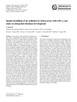
Figures 1A and 1B.
“Before” and “after”
pictures show renderings
of the desired “look” as
a pre-construction
Computer Graphic Image
(CGI) on the left, while
the actual appearance of
nearly completed room
is shown in the photo on
the right. CGI and photo
courtesy of Sicor Inc.
Continued on page 32.
30
PHARMACEUTICAL ENGINEERING MARCH/APRIL 2004
Process Piping - Case Study
“On a similar project, computer simulations
saved an estimated 10% of the project cost and helped the owner
to get what they wanted.”
(BPE-2002) originally published in 1997, and the ISPE
Baseline® Guides1,2 also have driven the quest for quality in
pharmaceutical piping systems. These standards were developed by industry leaders who recognized that good design and
efficient installation procedures are important for containing
costs both during construction and for the service life of the
systems.
This installation would be considered a “small” process
piping project with about 2,500 feet of stainless steel tubing
with a total of approximately 600 orbital welds. This works
out to be a weld every 4 to 5 feet. Sicor Inc. is nearly unique
in the number of products they produce with more than 100
different drugs made at this facility. Their products include
Active Pharmaceutical Ingredients (APIs) for use in various
products, Finished Dosage Products (FDP) (injectables), and
biopharmaceuticals such as human growth hormone and
human insulin.
Defining User Space
Senior Project Manager for Sicor, Stephan Muehlberger,
begins a project by defining the user space. He develops
computer simulations of the proposed spaces using software
which provides extremely accurate visualizations of how the
completed rooms and suites will appear when finished. The
end-user is most concerned with the appearance of those
areas with the highest requirements for cleanliness. He has
a certain “look” in mind for the high-visibility areas which
include the filling suite, the area of compounding, and the
component preparation area. Not coincidentally, these happen to be the areas with the highest ratio of process piping.
Once the location of equipment in these areas is established, engineers can concentrate on how to get the utilities
to the spaces. Computer simulation is a very powerful tool
that allows the viewer (engineer or contractor) to virtually
open doors and walk through a series of proposed areas and
to view the spaces from above to see how various pieces of
equipment will be placed in a room. From this perspective,
they are able to gauge the amount of walk-around space that
should be available around each component. The work space
must be uncrowded, clean, and orderly with everything in its
proper place.
The filling lines project has 20 cleanrooms ranging from
Class 100 up to Class 10,000. The number and location of
sinks and use points must be detailed in advance. Arrangements must be made for HEPA filters, HVAC, temperature
controls, and piping. To prevent crossing of piping and ducting or similar disorderly arrangements, the areas to be left
clear must be specified. A computerized presentation can
provide sufficient detail to serve as a guide for writing the job
specification and help to keep change orders to a minimum.
If a particular computer drawing of a process panel shows the
exact position of a valve with respect to the piping, this can
help serve as a guide for the installing contractor - Figures 1A
and 1B. On a similar project, computer simulations saved an
estimated 10% of the project cost and helped the owner to get
what they wanted.
General Contractor
The general contractor specializing in construction projects
for the Biotech and Pharmaceutical Industry was the liaison
between the architect engineering firm, the end user, and the
construction team. Project Executive, Larry Moore, was responsible for overseeing the entire project. The general contractor prepared the master document for the installation
called the Construction Qualification Program (CQP). The
CQP consisted of a set of written SOPs and guidelines for the
purpose of controlling the construction process. The procedures covered documentation compiling, system and equipment testing, and the requirements for Turnover Package
preparation.
Written procedures are considered to provide the best
assurance that the important systems and components of a
pharmaceutical manufacturing facility are installed in accordance with the specifications and that the proper installation
has been documented giving a high level of assurance that the
principles of current Good Manufacturing Practices (cGMP),
as interpreted and enforced by the United States Food and
Drug Administration (FDA), have been met.
The FDA does not tell people how to build a facility, but
rather checks to see that all the documentation is correct. End
users and their validation and QA people must demonstrate
that they are in compliance with 21 CFR 211.65 paragraph (a)
which states “Equipment shall be constructed so that surfaces
that contact components, in-process materials, or drug products shall not be reactive, additive, or absorptive so as to alter
the safety, identity, strength, quality, or purity of the drug
product beyond the official or other established requirements.”3
If any of the documentation submitted to the FDA is found to
be out of order, the FDA will start “pulling at threads” to get
at the root of the problem.
Installing Contractor
Project Manager Stephan Muehlberger said that in a perfect
world he would be able to just tell the vendor to “install the
process pipe” and it would be done not just to the standard,
but exactly the way he wanted it. Since it is not a perfect
world, he must have a relationship with the vendor and know
their level of experience and expertise. The installing contractor, who has done previous work for Sicor and are an
approved and preferred vendor, did design-assist and project
Continued on page 34.
32
PHARMACEUTICAL ENGINEERING MARCH/APRIL 2004
Process Piping - Case Study
Phase I, June 14 - July 30, 2002,
Demolition and Re-Installation of
Existing Systems
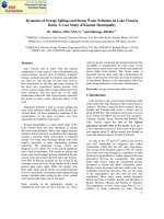
Figure 2. Welding operator installs an electrode in the orbital weld
head which is connected to an orbital welding power supply. A
water cooling unit is situated beneath the power supply. Photo
courtesy of Pro-Tech Process, Inc.
coordination and execution. Their welders are experienced in
the use of orbital welding equipment - Figure 2. They understand what’s required in terms of how the system should look,
how to do the isometrics, and the best way of supporting the
piping. Proper pipe support is important since the plant is in
California and must conform to requirements for seismic
zone 4.
IQD Turnover Package
In preparation for Phase I construction, the installing contractor prepared an IQD Turnover Package for each system
that was to be relocated including process gases, clean steam,
etc. The IQD Turnover Packages each contained a Scope of
Work statement, a list of project personnel and their brazing
certificate, or for welded systems, welder performance qualifications, Weld Procedure Specifications (WPS), and Procedure Qualification Records (PQR) in compliance with ASME
Section IX of the Boiler and Pressure Vessel Code.4 Also
included were welding equipment certifications, receiving
logs for materials, critical system isometric (ISO) drawings
for each of the systems, certificates of cleaned material, and
pressure test reports for various system components.
Welded systems had coupon logs, weld logs, borescope
logs, and passivation procedures and certificates. At the end
of the IQD Turnover Package, there was a sign-off sheet to be
turned over at the end of the shutdown for acceptance of the
work by the client. The Scope of Work for the shutdown was
to isolate and remove process gas lines from the first floor labs
in the demolition area and tie-in and re-route process piping
systems.
The installing contractor translated engineering drawings from the architect engineer from two- dimensional to
three-dimensional isometric construction drawings and then
verified that the drawings were “constructible.” The general
contractor obtained the necessary permits from the city to do
the work.
34
PHARMACEUTICAL ENGINEERING MARCH/APRIL 2004
The first phase of the piping installation was a shut-down to
accommodate a “Tenant Improvement” (TI) situation. This
involves relocation of the existing equipment and utilities in
the area where the new product lines were to be installed in
order to avoid interruption of the then-current production
schedule. The demolition phase was on a very tight schedule
with crews working around the clock. Bulldozers were used
for demolition of walls which were cut down and moved out in
large chunks; utilities, lights, phones, fire alarms, etc. were
all cut out and then equipment was relocated and re-installed. All process equipment, utilities, and piping had to fit
within very confined spaces and there could be no interference among the plumbing, electrical, concrete, carpenters
and other trades who had to work in the same space at the
same time to complete this phase within the allotted time.
Phase II
In preparation for Phase II, the installing contractor prepared a separate submittal package for each of the piping
systems which included the product lines and piping systems
for nitrogen (N2), Clean Air (CLA), Clean-In-place (CIP),
Water For Injection (WFI), Reverse Osmosis (RO) water,
Deionized (DI) water, product clean steam, and clean steam
condensate. For example, the WFI submittal package contained a specification for stainless steel piping materials,
such as tubing and fittings, and methods of attachment which
included flanges and gaskets, orbital welding, and valves.
The remainder of the book contained vendor product information and specifications for the above items as well as for
piping insulation material and instrumentation. An orbital
Weld Procedure Specification (WPS), qualifying the welding
procedure to ASME Sect. IX of the Boiler and Pressure Vessel
Code4 and Procedure Qualification Records (PQRs) for each of
the welders and isometric drawings for routing the WFI
system also were included in the package.
Typically, material availability drives the schedule which
means that items with long lead times must be ordered as
soon as possible. For this project, the long lead time items are
one-of-a kind custom pieces of equipment such as WFI heat
exchangers, valve clusters, and other process equipment.
Orbital Welding
During the past decade, the ratio of orbital welds to manual
in biopharmaceutical systems has increased to the point that
presently very few manual welds are done. Dr. Richard
Campbell of Purity Systems, Inc. reported at a recent ASME
BPE Standards meeting that about 99% of welds in
biopharmaceutical installations are now done with orbital
welding. The BPE standard requires that, if a manual weld
is done, it must be with the owner’s permission and it must be
inspected on the inside (ID) with a borescope as shown in
Figure 3.
The welding used in hygienic biopharmaceutical applications is autogenous orbital GTA welding. In this process, an
Process Piping - Case Study
arc is struck between a non-consumable tungsten electrode
and the weld joint. This takes place inside an enclosed weld
head in an inert gas atmosphere. The tube or fitting being
welded remains in place while the electrode in the weld head
rotor moves around the joint circumference to complete the
weld. Weld parameters such as welding current, electrode
travel speed, and pulse times are programmed into the
microprocessor-controlled power supplies (Figure 2) and stored
as weld programs or weld schedules for each size of tubing,
pipe, or component to be welded. Print-outs of weld schedules
are included in the weld qualification documents. The weld
joint configuration is a square butt preparation in which the
tube ends are cut square and machine-faced to fit together
without a gap.
The goal of orbital welding is to achieve a very high degree
of repeatability from weld to weld, not only to get high
productivity, but to provide the best quality system possible.
The welding power supply executes the weld parameters with
a high degree of accuracy weld after weld. It is up to the
installing contractor and his operators to control other factors that could affect weld repeatability. The welding operators received training in operation of the equipment and are
proficient at developing weld schedules for each size of tubing
and know how to cope with heat-to-heat variation in
weldability. Installing contractors have developed Standard
Operating Procedures (SOPs) detailing every aspect of the
orbital welding process.
Figure 3. Video borescope display showing I.D. weld bead from a
field weld and information recorded for each weld. Photo
courtesy of Purity Systems, Inc.
weld during welding, combining with chromium and precipitating as chromium carbide leaving the grain boundaries in
the Heat-Affected Zone (HAZ) reduced in chromium, and thus
subject to intergranular corrosive attack. However, since the
formation of chromium carbide is time and temperature
dependant, the precisely controlled heat input of orbital
welding makes this occurrence less likely than with manual
welding.
Concludes on page 36.
ASME BPE Standard
Sicor Inc. hired a third-party QA company to inspect their
welds. In addition to weld procedure qualification to ASME
Sect.IX and B31.35, inspectors used the visual criteria for
weld acceptance from the Materials Joining part of ASME
Bioprocessing Equipment Standard (BPE-2002).1 The BPE
Standard was originally published in 1997 and was revised in
2002. The BPE Standard was the first standard written for
the biopharmaceutical industry that specifically recommends
the use of orbital welding.
The Dimensions and Tolerances (DT) Part of the BPE
Standard has contributed to improved consistency of orbital
welding by specifying acceptance criteria for wall thicknesses
and ovality of weld ends of fittings and other components for
bioprocess systems. Since the welding current for orbital
welding is roughly proportional to wall thickness with about
1 amp of welding current for each 0.001 inch, a variation of
more than a few thousandths of an inch in wall thickness
could make a difference in weld bead penetration. Similarly,
the squareness of the weld end is controlled so that there will
be no significant gap between parts when secured in the weld
head. Good fit-up and alignment of parts for welding is
essential.
The material generally used in high purity
biopharmaceutical applications is 316 or 316L stainless steel.6
For welding, the reduced carbon content of 316L is preferred.
With higher carbon levels (0.080 wt.% in 316 compared to
0.035 wt.% in 316L), there is a chance of carbon migrating to
the grain boundaries in the area immediately adjacent to the
MARCH/APRIL 2004 PHARMACEUTICAL ENGINEERING
35
Process Piping - Case Study
In the interest of weldability, the DT Part of the BPE
standard has limited the sulfur range of type 316L stainless
steel used for fittings and weld ends of components to 0.005
to 0.017 weight% and recommends the use of tubing specified
to ASTM A270 S-2 Pharmaceutical Grade which has the
same sulfur range as the BPE. This is in contrast to the AISI
specification which lists a maximum sulfur concentration of
0.030 weight%, but no minimum. Heat-to-heat variation in
base metal chemistry of stainless steels results in differences
in weldability and is a major cause of weld inconsistency. The
limited sulfur range has eliminated much of the uncertainty
in fabrication and greatly increased the consistency of orbital
tube welding for those using this standard.7
When materials arrive on site, they are received and
logged by the installing contractor and then inspected and
logged by third-party QA. ASME B31.3 Process Piping Chapter VI distinguishes between examination and inspection.
Inspection applies to functions performed for the owner by the
owner’s inspector or the inspector’s delegates (QA), while
examination applies to quality control functions performed
by the manufacturer, fabricator or erector, in this case the
installing contractor (QC). Weld criteria are detailed in the
Materials Joining part of the BPE Standard.
References
1. ASME Bioprocessing Equipment Standard (BPE-2002),
American Society of Mechanical Engineers, Three Park
Ave., New York, NY 10016.
2. ISPE Baseline® Pharmaceutical Engineering Guide: Volume 4 - Water and Steam Systems, First Edition/January
2001, ISPE, 3109 W. Martin Luther King, Jr. Blvd., Suite
250, Tampa, FL 33607.
3. Code of Federal Regulations - Food and Drug Administration - Current Good Manufacturing Practice for the Manufacture, Processing, Packing, or Holding of Drugs - 21
CFR- Parts 210 & 211, Revised as of November 4, 1998.
4. ASME Sect. IX. Boiler and Pressure Vessel Code, American Society of Mechanical Engineers, Three Park Ave.,
New York, NY 10016.
5. ASME B31.3 Process Piping 1999 Edition. American Society of Mechanical Engineers, Three Park Ave., New York,
NY 10016.
6. Gonzalez, Michelle M., “Stainless Steel Tubing in the
Biotechnology Industry,” Pharmaceutical Engineering, Vol.
21, No. 5, 2001, pp.48-63.
7. Henon, Barbara. “Specifying the Sulfur Content of Type
316L Stainless Steel for Orbital Welding: Weldability vs.
Surface Finish,” Tube and Pipe Journal (TPJ), Vol. 14,
No.2, 2003, pp. 46-49.
36
PHARMACEUTICAL ENGINEERING MARCH/APRIL 2004
Acknowledgements
The authors would like to thank Joshua Lohnes and Michael
Aubin of Purity Systems, Inc., for sharing their expertise on
Quality Assurance and Daryl Roll and Steve Biggers of Astro
Pak for sharing their expertise on Passivation.
About the Authors
Barbara K. Henon, PhD, Manager of Technical Publications at Arc Machines, Inc., has
been employed by Arc Machines since 1984.
During this time, she has been an instructor
of orbital tube welding and has written articles on customer applications in the
biopharmaceutical, semiconductor, offshore,
and other industries which share a need for
high-quality welds. She also writes Operator Training Manuals for the company. Dr. Henon is Vice Chair of the Main
Committee of the ASME Bioprocessing Equipment Standard
and has been a member of the BPE Materials Joining Subcommittee since 1989. She also serves on several AWS and
SEMI Standards writing groups. She can be contacted by tel:
1-818/896-9556 or by e-mail:
Arc Machines, Inc., 10500 Orbital Way, Pacoima, CA
91331.
Stephan E. Muehlberger is a Senior Manager Project and Process Engineer at Sicor
Inc. He has been with Sicor since 1995. He
has been responsible for the integration of
sterile filling lines, inspection/packaging expansions, process compounding suites, facility infrastructure expansions (WFI, clean
steam, plant utilities). The current project is
a $19 million facility expansion incorporating two sterile
filling lines, two compounding lines, two compounding suites,
and a component preparation area. His previous experience
was as an engineer with a company specializing in plasma
cutting. He can be contacted by tel: 1-949/455-4791 or by email:
Sicor Pharmaceuticals, Inc., 19 Hughes St., Irvine, CA
92618.
Gene DePierro, President of Pro-Tech Process, Inc., started Pro-Tech in 1997 after
many years of process piping experience. He
worked for Fluor Daniel and Brown and
Root. Pro-Tech is the largest “open shop”
process piping contractor in Southern California. Pro-Tech specializes in process piping
and cGMP plumbing for pharmaceutical and
biotech installations. He can be contacted by tel: 1-858/4950573 or by e-mail:
Pro-Tech Process, Inc., 9484 Chesapeake Dr., Suite 806,
San Diego, CA 92123.