ARMBased Microcontroller
Bạn đang xem bản rút gọn của tài liệu. Xem và tải ngay bản đầy đủ của tài liệu tại đây (13.85 MB, 1,015 trang )
SAM DA1
ARM-Based Microcontroller
DATASHEET
Description
The Atmel® SAM DA1 is a series of low-power automotive microcontrollers using the
32-bit ARM® Cortex®-M0+ processor with 32 to 64 pins and up to 64KB of Flash, up to
8KB of SRAM and up to 2KB Read-While-Write (RWW) Flash section. The SAM DA1
devices operate at a maximum frequency of 48MHz and reach 2.14 Coremark/MHz.
They are designed for simple and intuitive migration with identical peripheral modules,
hex compatible code, identical linear address map and pin-compatible migration paths
between all devices in the product series. All devices include intelligent and flexible
peripherals, patented Atmel Event System for inter-peripheral signaling.
The Atmel SAM DA1 devices have the following features: In-system programmable
Flash, eight-channel direct memory access (DMA) controller, 12-channel event system,
programmable interrupt controller, up to 52 programmable I/O pins, 32-bit real-time
clock and calendar, five 16-bit timer/counters (TC) and three 16-bit timer/counters for
control (TCC), where each TC can be configured to perform frequency and waveform
generation, accurate program execution timing or input capture with time and
frequency measurement of digital signals. The TCs can operate in 8- or 16-bit mode,
selected TCs can be cascaded to form a 32-bit TC, and three timer/counters have
extended functions optimized for motor, lighting and other control applications.
The series provides up to six serial communication modules (SERCOM) that each can
be configured to act as a USART, UART, SPI, I2C up to 3.4MHz, and LIN slave; up to
twenty-channel 350ksps 12-bit ADC with programmable gain and optional
oversampling and decimation supporting up to 16-bit resolution, one 10-bit 350ksps
DAC, two analog comparators with window mode, programmable watchdog timer,
brown-out detector and power-on reset and two-pin serial wire debug (SWD) program
and debug interface. Peripheral Touch Controller supporting capacitive buttons,
sliders, wheels and proximity sensing, one full-speed USB 2.0 embedded host and
device interface and one inter-IC sound controller (I2S).
All devices have accurate and low-power external and internal oscillators. All oscillators
can be used as a source for the system clock. Different clock domains can be
independently configured to run at different frequencies, enabling power saving by
running each peripheral at its optimal clock frequency, and thus maintaining a high
CPU frequency while reducing power consumption.
The SAM DA1 devices offer two software-selectable sleep modes, idle and standby. In
idle mode the CPU is stopped while all other functions can be kept running.
Atmel-9349A–SAM-DA1_Datasheet–10/2015
SMART
In standby all clocks and functions are stopped except those selected to continue running. The device supports
SleepWalking. SleepWalking allows peripherals to wake up from sleep based on predefined conditions, allowing the
CPU to wake up only when needed, e.g., when a threshold is crossed or a result is ready. The Peripheral Event System
supports synchronous and asynchronous events, allowing peripherals to receive, respond to and send events even in
standby mode. The Flash program memory can be reprogrammed in-system through the SWD interface. The same
interface can be used for non-intrusive on-chip application code debugging. A boot loader running in the device can use
any communication interface to download and upgrade the application program in the Flash memory.
Atmel® SAM DA1 devices are supported by a complete suite of program and system development tools, including C
compilers, macro-assemblers, program debugger/simulators, programmers and evaluation kits.
Features
z Processor
ARM Cortex-M0+ CPU running at up to 48MHz
Single-cycle hardware multiplier
z Micro trace buffer
z
z
z Memories
16/32/64KB in-system self-programmable Flash
0.5/1/2KB Read-While-Write (RWW) Flash section
z 4/4/8KB SRAM memory
z
z
z System
z
z
z
z
z
z
Power-on reset (POR) and brown-out detection (BOD)
Internal and external clock options with 48MHz digital frequency locked loop (DFLL48M) and 48MHz to 96MHz
fractional digital phase locked loop (FDPLL96M)
External interrupt controller (EIC)
16 external interrupts
One non-maskable interrupt
Two-pin serial wire debug (SWD) programming, test and debugging interface
z Low power
z
z
Idle and standby sleep modes
SleepWalking peripherals
z Peripherals
z
z
z
z
z
z
z
8-channel direct memory access controller (DMAC)
12-channel event system
Five 16-bit timer/counters (TC), configurable as either:
z One 16-bit TC with compare/capture channels
z One 8-bit TC with compare/capture channels
z One 32-bit TC with compare/capture channels, by using two TCs
Three 16-bit timer/counters for control (TCC), with extended functions:
z Up to four compare channels with optional complementary output
z Generation of synchronized pulse width modulation (PWM) pattern across port pins
z Deterministic fault protection, fast decay and configurable dead-time between complementary output
z Dithering for enhancing resolution with up to 5-bit and reduce quantization error
32-bit real time counter (RTC) with clock/calendar function
Watchdog timer (WDT)
CRC-32 generator
Atmel | SMART SAM DA1 [DATASHEET]
Atmel-9349A–SAM-DA1_Datasheet–10/2015
2
z
z
z
z
z
z
z
One full speed (12Mbps) universal serial bus (USB) 2.0 controller
z Device 2.0 and reduced-host low speed and full speed
z Flexible end-point configuration and management with dedicated DMA channels
z On-chip transceivers including pull-ups and serial resistors
z Crystal-less operation in device mode
Up to six serial communication interfaces (SERCOM), each configurable to operate as either:
z USART with full-duplex and single-wire half-duplex configuration
z I2C up to 3.4MHz
z SPI
z LIN slave
One two-channel inter-IC sound (I2S) interface
One 12-bit, 350ksps analog-to-digital converter (ADC) with up to 20 channels
z Differential and single-ended input
z 1/2x to 16x programmable gain stage
z Automatic offset and gain error compensation
z Oversampling and decimation in hardware to support 13-, 14-, 15- or 16-bit resolution
10-bit, 350ksps digital-to-analog converter (DAC)
Two analog comparators (AC) with window compare function
Peripheral Touch Controller (PTC)
z Up to 256-channel capacitive touch and proximity sensing
z I/O
z
Up to 52 programmable I/O pins
z Packages
64-pin TQFP
48-pin TQFP, QFN
z 32-pin TQFP, QFN
z
z
z Operating voltage
z
2.7V to 3.63V
z Temperature range
z
–40 to +105°C
Atmel | SMART SAM DA1 [DATASHEET]
Atmel-9349A–SAM-DA1_Datasheet–10/2015
3
1.
Configuration Summary
Table 1-1.
Configuration Summary
SAM DA1J
SAM DA1G
SAM DA1E
Pins
64
48
32
General Purpose I/O-pins
(GPIOs)
52
38
26
Flash
64/32/16KB
64/32/16KB
64/32/16KB
RWW Flash section
2KB/1KB/512B
2KB/1KB/512B
2KB/1KB/512B
SRAM
8/4/4KB
8/4/4KB
8/4/4KB
Timer counter (TC) instances
5
5
5
Waveform output channels per
TC instance
2
2
2
Timer Counter for Control (TCC)
instances
3
3
3
Waveform output channels per
TCC
8/4/2
8/4/2
6/4/2
DMA channels
8
8
8
USB interface
1
1
1
Serial communication interface
(SERCOM) instances
6
6
4
Inter-IC sound interface (I2S)
1
1
1
Analog-to-digital converter
(ADC) channels
20
14
10
Analog comparators (AC)
2
2
2
Digital-to-analog converter
(DAC) channels
1
1
1
Real-time counter (RTC)
Yes
Yes
Yes
RTC alarms
1
1
1
RTC compare values
1 × 32-bit value or
2 × 16-bit values
1 × 32-bit value or
2 × 16-bit values
1 × 32-bit value or
2 × 16-bit values
External interrupt lines
16
16
16
Peripheral Touch Controller
(PTC) X and Y lines
16x16
12x10
10x6
Maximum CPU frequency
Packages
48MHz
TQFP
QFN
TQFP
QFN
TQFP
32.768kHz crystal oscillator (XOSC32K)
0.4-32MHz crystal oscillator (XOSC)
32.768kHz internal oscillator (OSC32K)
8MHz high-accuracy internal oscillator (OSC8M)
48MHz digital frequency locked loop (DFLL48M)
96MHz fractional digital phase locked loop (FDPLL96M)
Clocks
Event system channels
12
12
12
Software debug interface
Yes
Yes
Yes
Watchdog timer (WDT)
Yes
Yes
Yes
Atmel | SMART SAM DA1 [DATASHEET]
Atmel-9349A–SAM-DA1_Datasheet–10/2015
4
2.
Ordering Information
Figure 2-1. Ordering Information
SAM DA1 E 14 A
-
A B T
Product Family
SAM D = Baseline Cortex-M MCU
Package Carrier
T = Tape and Reel
Product Series
A1 = Automotive Basic feature set + DMA,
Adv Timers, USB, I2S, PTC
Plating Material and Temp Grade
B = -40°C to +105°C Matte Sn plating (only DA1)
Pin Count
E = 32 pins
G = 48 pins
J = 64 pins
Package Type
A = TQFP
M = QFN Wettable Flanks
Memory Density
14 = 16kB
15 = 32kB
16 = 64kB
Marketing Revision
A = Initial revision
2.1
B-versions
Table 2-1.
SAM DA1E
Ordering Code
FLASH (Bytes) SRAM (Bytes)
Package
Carrier Type
Temperature Grade
PTC, USB, I2S
ATSAMDA1E14A-ABT
16K
4K
TQFP32
Tape and reel
–40°C to +105°C
Yes
ATSAMDA1E14A-MBT
16K
4K
QFN32
Tape and reel
–40°C to +105°C
Yes
ATSAMDA1E15A-ABT
32K
4K
TQFP32
Tape and reel
–40°C to +105°C
Yes
ATSAMDA1E15A-MBT
32K
4K
QFN32
Tape and reel
–40°C to +105°C
Yes
ATSAMDA1E16A-ABT
64K
8K
TQFP32
Tape and reel
–40°C to +105°C
Yes
ATSAMDA1E16A-MBT
64K
8K
QFN32
Tape and reel
–40°C to +105°C
Yes
Package
Carrier Type
Temperature Grade
PTC, USB, I2S
Table 2-2.
SAM DA1G
Ordering Code
FLASH (Bytes) SRAM (Bytes)
ATSAMDA1G14A-ABT
16K
4K
TQFP48
Tape and reel
–40°C to +105°C
Yes
ATSAMDA1G14A-MBT
16K
4K
QFN48
Tape and reel
–40°C to +105°C
Yes
ATSAMDA1G15A-ABT
32K
4K
TQFP48
Tape and reel
–40°C to +105°C
Yes
ATSAMDA1G15A-MBT
32K
4K
QFN48
Tape and reel
–40°C to +105°C
Yes
ATSAMDA1G16A-ABT
64K
8K
TQFP48
Tape and reel
–40°C to +105°C
Yes
ATSAMDA1G16A-MBT
64K
8K
QFN48
Tape and reel
–40°C to +105°C
Yes
Atmel | SMART SAM DA1 [DATASHEET]
Atmel-9349A–SAM-DA1_Datasheet–10/2015
5
Table 2-3.
SAM DA1J
Ordering Code
FLASH (Bytes) SRAM (Bytes)
Package
Carrier Type
Temperature Grade
PTC, USB, I2S
ATSAMDA1J14A-ABT
16K
4K
TQFP64
Tape and reel
–40°C to +105°C
Yes
ATSAMDA1J15A-ABT
32K
4K
TQFP64
Tape and reel
–40°C to +105°C
Yes
ATSAMDA1J16A-ABT
64K
8K
TQFP64
Tape and reel
–40°C to +105°C
Yes
Atmel | SMART SAM DA1 [DATASHEET]
Atmel-9349A–SAM-DA1_Datasheet–10/2015
6
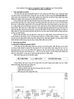
Block Diagram
SWCLK
CORTEX-M0+
Processor
Fmax 48MHz
Serial
Wire
SWDIO
Memory
Trace Buffer
I/O Bus
64/32/16KB NVM
2KB/1KB/512B
RWW Flash Section
8/4/4KB
SRAM
NVM
Controller
SRAM
Controller
Cache
Device
Service
Unit
M
M
M
S
High Speed
Bus Matrix
Peripheral
Access Controller
S
DMA
M
USB FS
Device
Mini-Host
S
AHB-APB
Bridge A
DM
SOF 1kHz
AHB-APB
Bridge C
Peripheral
Access Controller
Peripheral
Access Controller
DMA
System Controller
BOD33
S
DP
S
AHB-APB
Bridge B
PORT
6 x SERCOM
PAD0
PAD1
PAD2
PAD3
5 x Timer/Counter
WO0
WO1
VREF
OSC32K
XIN32
XOSC32K
DMA
OSC8M
XOUT32
DFLL48M
XIN
XOSC
FDPLL96M
XOUT
3 x Timer/Counter
for Control
Power Manager
Clock
Controller
RESETN
Reset
Controller
Sleep
Controller
Generic Clock
Controller
20-channel
12-bit ADC 350KSPS
10-bit DAC
Peripheral
Touch
Controller
Watchdog
Timer
VREFA
VREFB
AIN[3..0]
VOUT
DMA
Real Time
Counter
WOn
AIN[19..0]
DMA
2 Analog
Comparators
GCLK_IO[7..0]
WO0
WO1
PORT
DMA
Event System
3.
VREFP
X[15..0]
Y[15..0]
EXTINT[15..0]
NMI
External Interrupt
Controller
DMA
Inter-IC
Sound
Controller
MCK
SCK
WS
SDI
SDO
Atmel | SMART SAM DA1 [DATASHEET]
Atmel-9349A–SAM-DA1_Datasheet–10/2015
7
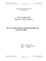
Pinout
64
63
62
61
60
59
58
57
56
55
54
53
52
51
50
49
PB03
PB02
PB01
PB00
PB31
PB30
PA31
PA30
VDDIN
VDDCORE
GND
PA28
RESETN
PA27
PB23
PB22
Figure 4-1. SAM DA1J
48
47
46
45
44
43
42
41
40
39
38
37
36
35
34
33
1
2
3
4
5
6
7
8
9
10
11
12
13
14
15
16
VDDIO
GND
PA25
PA24
PA23
PA22
PA21
PA20
PB17
PB16
PA19
PA18
PA17
PA16
VDDIO
GND
17
18
19
20
21
22
23
24
25
26
27
28
29
30
31
32
PA00
PA01
PA02
PA03
PB04
PB05
GNDANA
VDDANA
PB06
PB07
PB08
PB09
PA04
PA05
PA06
PA07
PA08
PA09
PA10
PA11
VDDIO
GND
PB10
PB11
PB12
PB13
PB14
PB15
PA12
PA13
PA14
PA15
4.
Digital Pin
Analog Pin
Oscillator
Ground
Input Supply
Regulated Output Supply
Reset Pin
Atmel | SMART SAM DA1 [DATASHEET]
Atmel-9349A–SAM-DA1_Datasheet–10/2015
8
PA28
RESETN
PA27
41
40
PB23
PB22
VDDCORE
GND
43
39
38
37
PB02
PA31
PA30
VDDIN
47
46
45
44
42
PB03
48
Figure 4-2. SAM DA1G
31
30
8
9
29
28
10
11
27
26
12
25
PA04
PA05
PA06
PA07
23
24
6
7
PA14
PA15
VDDANA
PB08
PB09
20
21
22
32
PB11
PA12
PA13
33
5
18
19
4
GND
PB10
PA03
GNDANA
14
15
16
17
35
34
13
36
2
3
PA09
PA10
PA11
VDDIO
1
PA08
PA00
PA01
PA02
VDDIO
GND
PA25
PA24
PA23
PA22
PA21
PA20
PA19
PA18
PA17
PA16
Digital Pin
Aanalog Pin
Oscillator
Ground
Input Supply
Regulated Output Supply
Reset Pin
Atmel | SMART SAM DA1 [DATASHEET]
Atmel-9349A–SAM-DA1_Datasheet–10/2015
9
PA31
PA30
VDDIN
VDDCORE
GND
PA28
RESETN
PA27
32
31
30
29
28
27
26
25
Figure 4-3. SAM DA1E
6
19
PA18
PA06
7
18
PA17
PA07
8
17
PA16
VDDANA
16
PA19
PA05
PA15
PA04
15
PA22
20
14
21
5
PA11
4
PA14
PA03
13
PA23
12
PA24
22
PA10
23
3
PA09
2
PA02
11
PA01
10
PA25
GND
24
PA08
1
9
PA00
Digital Pin
Analog Pin
Oscillator
Ground
Input Supply
Regulated Output Supply
Reset Pin
Atmel | SMART SAM DA1 [DATASHEET]
Atmel-9349A–SAM-DA1_Datasheet–10/2015
10
5.
Signal Descriptions List
The following table gives details on signal names classified by peripheral.
Signal Name
Function
Type
Active Level
Analog Comparators - AC
AIN[3:0]
AC Analog Inputs
Analog
CMP[:0]
AC Comparator Outputs
Digital
Analog Digital Converter - ADC
AIN[19:0]
ADC Analog Inputs
Analog
VREFA
ADC Voltage External Reference A
Analog
VREFB
ADC Voltage External Reference B
Analog
Digital Analog Converter - DAC
VOUT
DAC Voltage output
Analog
VREFA
DAC Voltage External Reference
Analog
External Interrupt Controller
EXTINT[15:0]
External Interrupts
Input
NMI
External Non-Maskable Interrupt
Input
Generic Clock Generator - GCLK
GCLK_IO[7:0]
Generic Clock (source clock or generic clock generator output)
I/O
Inter-IC Sound Controller - I2S
MCK[1..0]
Master Clock
I/O
SCK[1..0]
Serial Clock
I/O
FS[1..0]
I2S Word Select or TDM Frame Sync
I/O
SD[1..0]
Serial Data Input or Output
I/O
Power Manager - PM
RESETN
Reset
Input
Low
Serial Communication Interface - SERCOMx
PAD[3:0]
SERCOM I/O Pads
I/O
System Control - SYSCTRL
XIN
Crystal Input
Analog/ Digital
XIN32
32kHz Crystal Input
Analog/ Digital
XOUT
Crystal Output
Analog
XOUT32
32kHz Crystal Output
Analog
Timer Counter - TCx
Atmel | SMART SAM DA1 [DATASHEET]
Atmel-9349A–SAM-DA1_Datasheet–10/2015
11
Signal Name
Function
Type
WO[1:0]
Waveform Outputs
Output
Waveform Outputs
Output
Active Level
Timer Counter - TCCx
WO[1:0]
Peripheral Touch Controller - PTC
X[15:0]
PTC Input
Analog
Y[15:0]
PTC Input
Analog
General Purpose I/O - PORT
PA25 - PA00
Parallel I/O Controller I/O Port A
I/O
PA28 - PA27
Parallel I/O Controller I/O Port A
I/O
PA31 - PA30
Parallel I/O Controller I/O Port A
I/O
PB17 - PB00
Parallel I/O Controller I/O Port B
I/O
PB23 - PB22
Parallel I/O Controller I/O Port B
I/O
PB31 - PB30
Parallel I/O Controller I/O Port B
I/O
Universal Serial Bus - USB
DP
DP for USB
I/O
DM
DM for USB
I/O
SOF 1kHz
USB Start of Frame
I/O
Atmel | SMART SAM DA1 [DATASHEET]
Atmel-9349A–SAM-DA1_Datasheet–10/2015
12
6.
I/O Multiplexing and Considerations
6.1
Multiplexed Signals
By default each pin is controlled by the PORT as a general purpose I/O and alternatively can be assigned to one of the peripheral
functions A, B, C, D, E, F, G or H. To enable a peripheral function on a pin, the peripheral multiplexer enable bit in the pin configuration
register corresponding to that pin (PINCFGn.PMUXEN, n = 0-31) in the PORT must be written to one. The selection of peripheral
function A to H is done by writing to the peripheral multiplexing odd and even bits in the peripheral multiplexing register
(PMUXn.PMUXE/O) in the PORT.
PIN
A
SAM SAM SAM
DA1E DA1G DA1J I/O Pin Supply Type EIC
B
REF
ADC
AC
PTC
DAC
C
D
E
F
SERCOM
SEROMALT
TC/
TCC
TCC
G
H
AC/
CLK
1
1
1
PA00
VDD
ANA
E00
SERCOM TCC21/Pad[0] WO[0]
2
2
2
PA01
VDD
ANA
E01
SERCOM TCC21-PAD[1] WO[1]
3
3
3
PA02
VDD
ANA
E02
AIN[0]
Y[0]
4
PA03
VDD
ANA
ADC/
VREF
E03
ADAC/
VREFP
AIN[1]
Y[1]
5
PB04
VDD
ANA
E04
AIN[12]
Y[10]
6
PB05
VDD
ANA
E05
AIN[13]
Y[11]
9
PB06
VDD
ANA
E06
AIN[14]
Y[12]
10
PB07
VDD
ANA
E07
AIN[15]
Y[13]
7
11
PB08
VDD
ANA
E08
AIN[2]
Y[14]
SERCOM TC44-PAD[0] WO[0]
8
12
PB09
VDD
ANA
E09
AIN[3]
Y[15]
SERCOM TC44-PAD[1] WO[1]
5
9
13
PA04
VDD
ANA
E04
AIN[4] AIN[0] Y[2]
SERCOM TCC00-PAD[0] WO[0]
6
10
14
PA05
VDD
ANA
E05
AIN[5] AIN[1] Y[3]
SERCOM TCC00-PAD[1] WO[1]
7
11
15
PA06
VDD
ANA
E06
AIN[6] AIN[2] Y[4]
SERCOM TCC10-PAD[2] WO[0]
8
12
16
PA07
VDD
ANA
E07
AIN[7] AIN[3] Y[5]
SERCOM TCC10-PAD[3] WO[1]
11
13
17
PA08 VDDIO I2C NMI
AIN[16]
X[0]
SERCOM SERCOM TCC0- TCC1I2S/SD[1]
0-PAD[0] 2-PAD[0] WO[0] WO[2]
12
14
18
PA09 VDDIO I2C E09
AIN[17]
X[1]
SERCOM SERCOM TCC0- TCC1I2S/MCK[0]
0-PAD[1] 2-PAD[1] WO[1] WO[3]
13
15
19
PA10 VDDIO
E10
AIN[18]
X[2]
SERCOM SERCOM TCC1- TCC0GCLK_
I2S/SCK[0]
0-PAD[2] 2-PAD[2] WO[0] WO[2]
IO[4]
14
16
20
PA11 VDDIO
E11
AIN[19]
X[3]
SERCOM SERCOM TCC1- TCC00-PAD[3] 2-PAD[3] WO[1] WO[3]
19
23
PB10 VDDIO
E10
SERCOM TC5- TCC0GCLK_
I2S/MCK[1]
4-PAD[2] WO[0] WO[4]
IO[4]
20
24
PB11 VDDIO
E11
SERCOM TC5- TCC0GCLK_
I2S/SCK[1]
4-PAD[3] WO[1] WO[5]
IO[5]
4
4
ADC
VREFP
VOUT
I2S/SD[0]
I2S/FS[0]
Atmel | SMART SAM DA1 [DATASHEET]
Atmel-9349A–SAM-DA1_Datasheet–10/2015
GCLK_
IO[5]
13
6.1
Multiplexed Signals (Continued)
By default each pin is controlled by the PORT as a general purpose I/O and alternatively can be assigned to one of the peripheral
functions A, B, C, D, E, F, G or H. To enable a peripheral function on a pin, the peripheral multiplexer enable bit in the pin configuration
register corresponding to that pin (PINCFGn.PMUXEN, n = 0-31) in the PORT must be written to one. The selection of peripheral
function A to H is done by writing to the peripheral multiplexing odd and even bits in the peripheral multiplexing register
(PMUXn.PMUXE/O) in the PORT.
PIN
A
SAM SAM SAM
DA1E DA1G DA1J I/O Pin Supply Type EIC
B
REF
ADC
AC
C
PTC
DAC
D
SEROMALT
SERCOM
E
TC/
TCC
F
G
TCC
25
PB12 VDDIO I2C E12
X[12]
SERCOM
4-PAD[0]
26
PB13 VDDIO I2C E13
X[13]
SERCOM
4-PAD[1]
TC4- TCC0WO[1] WO[7]
GCLK_
IO[7]
27
PB14 VDDIO
E14
X[14]
SERCOM
4-PAD[2]
TC5WO[0]
GCLK_
IO[0]
28
PB15 VDDIO
E15
X[15]
SERCOM
4-PAD[3]
TC5WO[1]
GCLK_
IO[1]
21
29
PA12 VDDIO I2C E12
SERCOM SERCOM TCC2- TCC02-PAD[0] 4-PAD[0] WO[0] WO[6]
AC/
CMP[0]
22
30
PA13 VDDIO I2C E13
SERCOM SERCOM TCC2- TCC02-PAD[1] 4-PAD[1] WO[1] WO[7]
AC/
CMP[1]
15
23
31
PA14 VDDIO
E14
SERCOM SERCOM TC3- TCC02-PAD[2] 4-PAD[2] WO[0] WO[4]
GCLK_
IO[0]
16
24
32
PA15 VDDIO
E15
SERCOM SERCOM TC3- TCC02-PAD[3] 4-PAD[3] WO[1] WO[5]
GCLK_
IO[1]
17
25
35
PA16 VDDIO I2C E00
X[4]
SERCOM SERCOM TCC21-PAD[0] 3-PAD[0] WO[0]
GCLK_
IO[2]
18
26
36
PA17 VDDIO I2C E01
X[5]
SERCOM SERCOM TCC21-PAD[1] 3-PAD[1] WO[1]
GCLK_
IO[3]
19
27
37
PA18 VDDIO
E02
X[6]
SERCOM SERCOM TC3- TCC01-PAD[2] 3-PAD[2] WO[0] WO[2]
AC/
CMP[0]
20
28
38
PA19 VDDIO
E03
X[7]
SERCOM SERCOM TC3- TCC0I2S/SD[0]
1-PAD[3] 3-PAD[3] WO[1] WO[3]
AC/
CMP[1]
39
PB16 VDDIO I2C E00
SERCOM
5-PAD[0]
TC6- TCC0I2S/SD[1]
WO[0] WO[4]
GCLK_
IO[2]
40
PB17 VDDIO I2C E01
SERCOM
5-PAD[1]
TC6- TCC0GCLK_
I2S/MCK[0]
WO[1] WO[5]
IO[3]
29
41
PA20 VDDIO
E04
X[8]
SERCOM SERCOM TC7- TCC0GCLK_
I2S/SCK[0]
5-PAD[2] 3-PAD[2] WO[0] WO[6]
IO[4]
30
42
PA21 VDDIO
E05
X[9]
SERCOM SERCOM TC7- TCC05-PAD[3] 3-PAD[3] WO[1] WO[7]
21
31
43
PA22 VDDIO I2C E06
X[10]
SERCOM SERCOM TC4- TCC03-PAD[0] 5-PAD[0] WO[0] WO[4]
22
32
44
PA23 VDDIO I2C E07
X[11]
SERCOM SERCOM TC4- TCC0- USB/SOF GCLK_
3-PAD[1] 5-PAD[1] WO[1] WO[5]
1kHz
IO[7]
23
33
45
PA24 VDDIO
E12
SERCOM SERCOM TC5- TCC13-PAD[2] 5-PAD[2] WO[0] WO[2]
USB/DM
24
34
46
PA25 VDDIO
E13
SERCOM SERCOM TC5- TCC13-PAD[3] 5-PAD[3] WO[1] WO[3]
USB/DP
37
49
PB22 VDDIO
E06
SERCOM TC75-PAD[2] WO[0]
GCLK_
IO[0]
38
50
PB23 VDDIO
E07
SERCOM TC75-PAD[3] WO[1]
GCLK_
IO[1]
39
51
PA27 VDDIO
E15
25
TC4- TCC0WO[0] WO[6]
H
AC/
CLK
I2S/FS[1]
I2S/FS[0]
GCLK_
IO[6]
GCLK_
IO[5]
GCLK_
IO[6]
GCLK_
IO[0]
Atmel | SMART SAM DA1 [DATASHEET]
Atmel-9349A–SAM-DA1_Datasheet–10/2015
14
6.1
Multiplexed Signals (Continued)
By default each pin is controlled by the PORT as a general purpose I/O and alternatively can be assigned to one of the peripheral
functions A, B, C, D, E, F, G or H. To enable a peripheral function on a pin, the peripheral multiplexer enable bit in the pin configuration
register corresponding to that pin (PINCFGn.PMUXEN, n = 0-31) in the PORT must be written to one. The selection of peripheral
function A to H is done by writing to the peripheral multiplexing odd and even bits in the peripheral multiplexing register
(PMUXn.PMUXE/O) in the PORT.
PIN
A
SAM SAM SAM
DA1E DA1G DA1J I/O Pin Supply Type EIC
B
REF
ADC
AC
C
PTC
DAC
D
SEROMALT
SERCOM
E
TC/
TCC
F
G
H
AC/
CLK
TCC
27
41
53
PA28 VDDIO
E08
TC6WO[1]
GCLK_
IO[0]
31
45
57
PA30 VDDIO
E10
SERCOM TCC11-PAD[2] WO[0]
SWCLK
32
46
58
PA31 VDDIO
E11
SERCOM TCC11-PAD[3] WO[1]
SWIO
59
PB30 VDDIO I2C E14
SERCOM TCC0- TCC15-PAD[0] WO[0] WO[2]
60
PB31 VDDIO I2C E15
SERCOM TCC0- TCC15-PAD[1] WO[1] WO[3]
61
PB00
VDD
ANA
E00
AIN[8]
Y[6]
SERCOM TC75-PAD[2] WO[0]
62
PB01
VDD
ANA
E01
AIN[9]
Y[7]
SERCOM TC75-PAD[3] WO[1]
47
63
PB02
VDD
ANA
E02
AIN[10]
Y[8]
SERCOM TC65-PAD[0] WO[0]
48
64
PB03
VDD
ANA
E03
AIN[11]
Y[9]
SERCOM TC65-PAD[1] WO[1]
Atmel | SMART SAM DA1 [DATASHEET]
Atmel-9349A–SAM-DA1_Datasheet–10/2015
GCLK_
IO[0]
15
6.2
Other Functions
6.2.1
Oscillator Pinout
The oscillators are not mapped to the normal PORT functions and their multiplexing are controlled by registers in the
System Controller (SYSCTRL).
6.2.2
Oscillator
Supply
XOSC
VDDIO
XOSC32K
VDDANA
Signal
I/O Pin
XIN
PA14
XOUT
PA15
XIN32
PA00
XOUT32
PA01
Serial Wire Debug Interface Pinout
Only the SWCLK pin is mapped to the normal PORT functions. A debugger cold-plugging or hot-plugging detection will
automatically switch the SWDIO port to the SWDIO function.
Signal
Supply
I/O Pin
SWCLK
VDDIO
PA30
SWDIO
VDDIO
PA31
Atmel | SMART SAM DA1 [DATASHEET]
Atmel-9349A–SAM-DA1_Datasheet–10/2015
16
ADC
PA[7:2]
PB[9:0]
VDDIO
VDDIN
GND
Power Domain Overview
VDDCORE
7.1
GNDANA
Power Supply and Start-Up Considerations
VDDANA
7.
VOLTAGE
REGULATOR
PB[31:10]
OSC8M
PA[13:8]
BOD12
XOSC
AC
PA[15:14]
PA[31:16]
DAC
Digital Logic
(CPU, peripherals)
PA[1:0]
XOSC32K
POR
DFLL48M
OSC32K
OSCULP32K
7.2
Power Supply Considerations
7.2.1
Power Supplies
BOD33
FDPLL96M
The Atmel® SAM DA1 has several different power supply pins:
z
VDDIO: Powers I/O lines, OSC8M and XOSC. Voltage is 2.7V to 3.63V.
z
VDDIN: Powers I/O lines and the internal regulator. Voltage is 2.7V to 3.63V.
z
VDDANA: Powers I/O lines and the ADC, AC, DAC, PTC, OSCULP32K, OSC32K, XOSC32K. Voltage is 2.7V to
3.63V.
z
VDDCORE: Internal regulated voltage output. Powers the core, memories, peripherals, DFLL48M and
FDPLL96M. Voltage is 1.2V.
The same voltage must be applied to both VDDIN, VDDIO and VDDANA. This common voltage is referred to as VDD in
the datasheet.
The ground pins, GND, are common to VDDCORE, VDDIO and VDDIN. The ground pin for VDDANA is GNDANA.
For decoupling recommendations for the different power supplies, refer to the schematic checklist.
Atmel | SMART SAM DA1 [DATASHEET]
Atmel-9349A–SAM-DA1_Datasheet–10/2015
17
Refer to “Schematic Checklist” on page 988 for details.
Refer to ref for power supply connections for I/O pins TBD.
7.2.2
Voltage Regulator
The SAM DA1 voltage regulator has two different modes:
7.2.3
z
Normal mode: To be used when the CPU and peripherals are running
z
Low Power (LP) mode: To be used when the regulator draws small static current. It can be used in standby mode
Typical Powering Schematics
The SAM DA1 uses a single supply from 2.7V to 3.63V.
The following figure shows the recommended power supply connection.
Figure 7-1. Power Supply Connection
SAM DA1
Main Supply
(2.7V to 3.63V)
VDDIO
VDDANA
VDDIN
VDDCORE
GND
GNDANA
7.2.4
Power-Up Sequence
7.2.4.1
Minimum Rise Rate
The integrated power-on reset (POR) circuitry monitoring the VDDANA power supply requires a minimum rise rate. Refer
to the “Electrical Characteristics” on page 939 for details.
Atmel | SMART SAM DA1 [DATASHEET]
Atmel-9349A–SAM-DA1_Datasheet–10/2015
18
7.2.4.2
Maximum Rise Rate
The rise rate of the power supply must not exceed the values described in Electrical Characteristics. Refer to the
“Electrical Characteristics” on page 939 for details.
7.3
Power-Up
This section summarizes the power-up sequence of the SAM DA1. The behavior after power-up is controlled by the
Power Manager. Refer to “PM – Power Manager” on page 111 for details.
7.3.1
Starting of Clocks
After power-up, the device is set to its initial state and kept in reset, until the power has stabilized throughout the device.
Once the power has stabilized, the device will use a 1MHz clock. This clock is derived from the 8MHz Internal Oscillator
(OSC8M), which is divided by eight and used as a clock source for generic clock generator 0. Generic clock generator 0
is the main clock for the Power Manager (PM).
Some synchronous system clocks are active, allowing software execution.
Refer to the “Clock Mask Register” section in “PM – Power Manager” on page 111 for the list of default peripheral clocks
running. Synchronous system clocks that are running are by default not divided and receive a 1MHz clock through
generic clock generator 0. Other generic clocks are disabled except GCLK_WDT, which is used by the Watchdog Timer
(WDT).
7.3.2
I/O Pins
After power-up, the I/O pins are tri-stated.
7.3.3
Fetching of Initial Instructions
After reset has been released, the CPU starts fetching PC and SP values from the reset address, which is 0x00000000.
This address points to the first executable address in the internal flash. The code read from the internal flash is free to
configure the clock system and clock sources. Refer to “PM – Power Manager” on page 111, “GCLK – Generic Clock
Controller” on page 89 and “SYSCTRL – System Controller” on page 144 for details. Refer to the ARM Architecture
Reference Manual for more information on CPU startup ().
7.4
Power-On Reset and Brown-Out Detector
The SAM DA1 embeds three features to monitor, warn and/or reset the device:
z
POR: Power-on reset on VDDANA
z
BOD33: Brown-out detector on VDDANA
z
BOD12: Voltage Regulator Internal Brown-out detector on VDDCORE. The Voltage Regulator Internal BOD is
calibrated in production and its calibration configuration is stored in the NVM User Row. This configuration should
not be changed if the user row is written to assure the correct behavior of the BOD12.
Figure TBD
7.4.1
Power-On Reset on VDDANA
POR monitors VDDANA. It is always activated and monitors voltage at startup and also during all the sleep modes. If
VDDANA goes below the threshold voltage, the entire chip is reset.
7.4.2
Brown-Out Detector on VDDANA
BOD33 monitors VDDANA. Refer to “SYSCTRL – System Controller” on page 144 for details.
7.4.3
Brown-Out Detector on VDDCORE
Once the device has started up, BOD12 monitors the internal VDDCORE.
Atmel | SMART SAM DA1 [DATASHEET]
Atmel-9349A–SAM-DA1_Datasheet–10/2015
19
8.
Product Mapping
Figure 8-1. Atmel | SMART SAM DA1 Product Mapping
Global Memory Space
Code
0x00000000
0x00000000
Internal Flash
Code
0x00100000
0x1FFFFFFF
0x20000000
SRAM
0x20008000
Internal
RWW section
AHB-APB Bridge C
SRAM
0x42000000
Internal SRAM
0x42000400
PAC2
0x20000000
0x20007FFF
Undefined
EVSYS
AHB-APB
0x42000800
AHB-APB
Bridge A
0x42000C00
SERCOM0
0x40000000
0x40000000
Peripherals
SERCOM1
0x42001000
0x41000000
SERCOM2
AHB-APB
Bridge B
0x43000000
Reserved
0x60000000
0x42001400
SERCOM3
0x42000000
AHB-APB
Bridge C
0x42001800
SERCOM4
0x42FFFFFF
0x42001C00
SERCOM5
System
Undefined
0xE0000000
0x42002000
Reserved
0x60000200
Reserved
TCC0
0xE000E000
0x42002400
SCS
0xE0000000
TCC1
0xE000F000
System
0x42002800
Reserved
TCC2
0xE00FF000
0xFFFFFFFF
0x42002C00
ROMTable
TC3
0xE0100000
0x42003000
Reserved
TC4
0xFFFFFFFF
AHB-APB Bridge A
0x42003800
PAC1
PAC0
0x41002000
0x40000400
0x42003C00
0x41004000
0x41004400
0x42004400
0x41004800
0x41005000
RTC
0x42004C00
PTC
0x42005000
I2S
MTB
EIC
0x41007000
0x40001C00
DAC
Reserved
0x41006000
0x40001800
AC
0x42004800
DMAC
WDT
0x40001400
ADC
PORT
GCLK
0x40001000
TC7
0x42004000
NVMCTRL
SYSCTRL
0x40000C00
TC6
DSU
PM
0x40000800
TC5
AHB-APB Bridge B
0x41000000
0x40000000
Reserved
0x40FFFFFF
0x42003400
0x42005400
Reserved
0x41FFFFFF
Reserved
0x42FFFFFF
This figure represents the full configuration of the Atmel® SAM DA1 with maximum Flash and SRAM capabilities and a full set of
peripherals. Refer to the “Configuration Summary” on page 4 for details.
Atmel | SMART SAM DA1 [DATASHEET]
Atmel-9349A–SAM-DA1_Datasheet–10/2015
20
9.
Automotive Quality Grade
The SAM DA1 have been developed and manufactured according to the most stringent requirements of the international
standard ISO-TS 16949. This data sheet contains limit values extracted from the results of extensive characterization
(temperature and voltage). The quality and reliability of the SAM DA1 have been verified during regular product
qualification as per AEC-Q100 grade 1.
As indicated in the ordering information paragraph, the product is available in only one temperature grade, see Table 9-1.
Table 9-1.
10.
Temperature Grade Identification for Automotive Products
Temperature
Temperature Identifier
Comments
–40°C; +105°C
B
Full automotive temperature range
Data Retention
Reliability qualification results show that the projected data retention failure rate is much less than 1 PPM over 20 years
at 85°C or 100 years at 25°C.
Atmel | SMART SAM DA1 [DATASHEET]
Atmel-9349A–SAM-DA1_Datasheet–10/2015
21
11.
Memories
11.1
Embedded Memories
z
z
11.2
Internal high-speed flash with Read-While-Write (RWW) capability on section of the array
z
Pipelined flash architecture, allowing burst reads from sequential flash locations, hiding penalty of 1 wait
state access
z
Pipelined flash architecture typically reduces the cycle penalty of 1 wait state operation compared to 0 wait
state operation
z
100 000 write cycles, 15-year data retention capability
z
Sector lock capabilities, bootloader protection, security bit
z
32 fuses, erased during chip erase
z
User page for data to be preserved during chip erase
z
32-bit data out (read data bus)
z
16-bit data in (programming data bus)
z
Random read access (32 bits)
z
24MHz @ 2.70V
z
12MHz @ 1.80V
z
Non-volatile calibration bits are loaded from Flash aux row(s) during system startup (no real NVM fuses
supported)
z
No RWW (Read FLASH write Flash)
z
Typical Endurance (# erase/write cycles) 10k (T=25°C)
z
Data retention 10 years (T=85°C)
z
Erase page < 5ms - tbc
z
Program page < 5ms - tbc
z
Flash erase/write protection (3) - tbd
z
NVM security and NVM access control - tbd
(1)
(2)
Internal high-speed RAM, single-cycle access at full speed
Physical Memory Map
The High-Speed bus is implemented as a bus matrix. All High-Speed bus addresses are fixed, and they are never
remapped in any way, even during boot. The 32-bit physical address space is mapped as follow:
Table 11-1. SAM DA1 physical memory map(1)
Size
Memory
1.
Start address
SAMDA1x16
SAMDA1x15
SAMDA1x14
Embedded Flash
0x00000000
64Kbytes
32Kbytes
16Kbytes
Internal RWW section
0x00010000
2Kbytes
1Kbytes
512bytes
Embedded SRAM
0x20000000
8Kbytes
4Kbytes
4Kbytes
Self-programming supported by programming FLASH by running code from SRAM.
2.
XMEGA defines min 25 years @55°C.
3.
Configurable (in terms of size and protection level) area in Flash that is protected from application and debugger overwrite/erase.
Atmel | SMART SAM DA1 [DATASHEET]
Atmel-9349A–SAM-DA1_Datasheet–10/2015
22
Size
Memory
Start address
SAMDA1x16
SAMDA1x15
SAMDA1x14
Peripheral Bridge A
0x40000000
64Kbytes
64Kbytes
64Kbytes
Peripheral Bridge B
0x41000000
64Kbytes
64Kbytes
64Kbytes
Peripheral Bridge C
0x42000000
64Kbytes
64Kbytes
64Kbytes
Note:
1.
x = G, J or E. Refer to “Ordering Information” on page 5 for details.
Table 11-2. Flash memory parameters(1)
Device
Flash size
Number of pages
Page size
SAMDA1x16
64Kbytes
1024
64 bytes
SAMDA1x15
32Kbytes
512
64 bytes
SAMDA1x14
16Kbytes
256
64 bytes
Note:
1.
x = G, J or E. Refer to “Ordering Information” on page 5 for details.
2.
The number of pages (NVMP) and page size (PSZ) can be read from the NVM Pages and Page Size bits in
the NVM Parameter register in the NVMCTRL (PARAM.NVMP and PARAM.PSZ, respectively). Refer to
PARAM for details.
Table 11-3. RWW section parameters
Device
Flash size
Number of pages
Page size
SAMDA0x16
2Kbytes
32
64 bytes
SAMDA0x15
1Kbytes
16
64 bytes
SAMDA0x14
512bytes
8
64 bytes
Atmel | SMART SAM DA1 [DATASHEET]
Atmel-9349A–SAM-DA1_Datasheet–10/2015
23
11.3
NVM Calibration and Auxiliary Space
The device calibration data are stored in different sections of the NVM calibration and auxiliary space presented in Figure
11-1.
Figure 11-1. Calibration and Auxiliary Space
AUX1
0x00806040
0x00800000
Calibration and
auxiliary space
Area 4: Software
calibration area (256bits)
NVM base address +
0x00800000
0x00806020
Area 4 offset address
Area 3: Reserved
(128bits)
NVM base address
+ NVM size
0x00806010
NVM main address
space
Area 2: Device configuration
area (64 bits)
0x00806008
Area 2 offset address
Area 1: Reserved (64 bits)
0x00806000
0x00000000
Area 3 offset address
Area 1 address offset
NVM Base Address
0x00806000
AUX1
AUX1 offset address
0x00804000
AUX0 – NVM User
Row
0x00800000
Automatic calibration
row
AUX0 offset address
Calibration and auxiliary
space address offset
The values from the automatic calibration row are loaded into their respective registers at startup.
11.3.1 NVM User Row Mapping
The NVM User Row contains calibration data that are automatically read at device power on.
The NVM User Row can be read at address 0x804000.
To write the NVM User Row refer to “NVMCTRL – Non-Volatile Memory Controller” on page 354.
Note that when writing to the user row the values do not get loaded by the other modules on the device until a device
reset occurs.
Atmel | SMART SAM DA1 [DATASHEET]
Atmel-9349A–SAM-DA1_Datasheet–10/2015
24
Table 11-4. NVM User Row Mapping
Bit Position
Name
Usage
2:0
BOOTPROT
3
Reserved
6:4
EEPROM
7
Reserved
13:8
BOD33 Level
BOD33 Threshold Level at power on. Refer to BOD33 register.
Default value = 7.
14
BOD33 Enable
BOD33 Enable at power on . Refer to BOD33 register. Default value = 1.
16:15
BOD33 Action
BOD33 Action at power on. Refer to BOD33 register. Default value = 1.
24:17
Reserved
25
WDT Enable
WDT Enable at power on. Refer to WDT CTRL register.
Default value = 0.
26
WDT Always-On
WDT Always-On at power on. Refer to WDT CTRL register.
Default value = 0.
30:27
WDT Period
WDT Period at power on. Refer to WDT CONFIG register.
Default value = 0x0B.
34:31
WDT Window
WDT Window mode time-out at power on. Refer to WDT CONFIG register.
Default value = 0x05.
38:35
WDT EWOFFSET
WDT Early Warning Interrupt Time Offset at power on. Refer to WDT
EWCTRL register. Default value = 0x0B.
39
WDT WEN
WDT Timer Window Mode Enable at power on. Refer to WDT CTRL register.
Default value = 0.
40
BOD33 Hysteresis
BOD33 Hysteresis configuration at power on. Refer to BOD33 register.
Default value = 0.
41
Reserved
47:42
Reserved
63:48
LOCK
Used to select one of eight different bootloader sizes. Refer to “NVMCTRL –
Non-Volatile Memory Controller” on page 354. Default value = 7.
Used to select one of eight different EEPROM sizes. Refer to “NVMCTRL –
Non-Volatile Memory Controller” on page 354. Default value = 7.
Voltage Regulator Internal BOD (BOD12) configuration. These bits are written
in production and must not be changed. Default value = 0x70.
Voltage Regulator Internal BOD(BOD12) configuration. This bit is written in
production and must not be changed. Default value = 0.
NVM Region Lock Bits. Refer to “NVMCTRL – Non-Volatile Memory
Controller” on page 354.
Default value = 0xFFFF.
11.3.2 NVM Software Calibration Area Mapping
The NVM Software Calibration Area contains calibration data that are measured and written during production test.
These calibration values should be read by the application software and written back to the corresponding register.
The NVM Software Calibration Area can be read at address 0x806020.
The NVM Software Calibration Area can not be written.
Atmel | SMART SAM DA1 [DATASHEET]
Atmel-9349A–SAM-DA1_Datasheet–10/2015
25