A high order SMC PID face simulation on torpedo
Bạn đang xem bản rút gọn của tài liệu. Xem và tải ngay bản đầy đủ của tài liệu tại đây (352.1 KB, 13 trang )
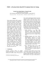
International Journal of Information Technology, Control and Automation (IJITCA) Vol.2, No.1, January 2012
A High Order Sliding Mode Control with PID
Sliding Surface: Simulation on a Torpedo
Ahmed Rhif
Department of Electronics Engineering, High Institute of Applied Sciences and
Technologies, Sousse, Tunisia
(Institut Supérieur des Sciences Appliquées et de Technologie de Sousse)
E-mail:
việc điều khiển
vị trí và
tốc độ là một vấn đề thực sự từ các khâu dẫn bởi vì hệ phi tuyến bậc cao và nhiễu
ngoài. Việc điều khiển hệ phi tuyến dựa trên nhiều cách tiếp cận khác nhau, cùng với SMC. SMC cho hiệu quả
cao, có thể thấy SMC được chú trọng trong nhiều nghiên cứu khác nhau.
Ưu điểm SMC là cứng đối với nhiễu và sai số mô hình.
ABSTRACT Nhược điểm là hiện tượng chattering vì vậy phần không liên tục của bộ điều khiển này sẽ gây hại đến hệ
thống.
Position and speed control of the torpedo present a real problem for the actuators because of the high
level of the system non linearity and because of the external disturbances. The non linear systems control
is based on several different approaches, among it the sliding mode control. The sliding mode control has
proved its effectiveness through the different studies. The advantage that makes such an important
approach is its robustness versus the disturbances and the model uncertainties. However, this approach
implies a disadvantage which is the chattering phenomenon caused by the discontinuous part of this
control and which can have a harmful effect on the actuators. This paper deals with the basic concepts,
mathematics, and design aspects of a control for nonlinear systems that make the chattering effect lower.
As solution to this problem we will adopt as a starting point the high order sliding mode approaches then
the PID sliding surface. Simulation results show that this control strategy can attain excellent control
performance with no chattering problem.
KEYWORDS
Sliding mode control, PID controller, chattering phenomenon, nonlinear system.
1. INTRODUCTION
Modern torpedoes are the most effective marine weapons but they have a range much lower
than the anti-ship missiles. Torpedoes are propelled engine equipped with an explosive charge,
and sometimes with an internal guidance system that controls the direction, speed and depth.
The typical shape of a torpedo is a cigar of 6 m long with a diameter of 50 cm and weighs one
ton. The torpedoes are the main weapons of a submarine, but are also used by ships and by
aircraft. They are increasingly wire-guided (cable several thousand meters connects the
submarine making it possible to re-program or re-direct the machine according to the evolution
of the target). However, most modern torpedoes can be completely autonomous. They have
active sonar which makes them able to direct themselves to the target they have been designated
prior to launch. Other types of torpedoes for example self-possessed, and especially during the
second half of World War II, an acoustic sensor (passive sonar) allowed them to move to the
noise emitted by the engines of the target. However, sometimes this kind of torpedo locks on the
engine noise of the submarine pitcher, so the standard procedure was to dive low speed after
such a shot. Modern torpedoes are powered by steam or electricity. The former have speeds
ranging from 25 to 45 knots, and their scope ranges from 4 to 27 km. They consist of four
elements: the warhead, the air section, rear section and tail section. The warhead is filled with
explosive (181 to 363 kg). The steam-air section is about one third of the torpedo and contains
compressed air and fuel tanks and water for the propulsion system. The rear section contains the
turbine propulsion systems with the guidance and control of depth. Finally, the tail section
DOI:10.5121/ijitca.2012.2101
1
International Journal of Information Technology, Control and Automation (IJITCA) Vol.2, No.1, January 2012
contains the rudders, exhaust valves and propellers. Orders of a torpedo electric are similar to
those of steam torpedoes, but the tank air is replaced by batteries and the turbines by an electric
motor [1-2].
The sliding mode control has proved its effectiveness through the theoretical studies. Its
principal scopes of application are robotics and the electrical engines [3-10]. The advantage of
such a control is its robustness and its effectiveness versus the disturbances and the model
uncertainties. Indeed, to make certain the convergence of the system to the desired state, a high
level control is often requested. In addition, the discontinuous part of the control generates the
chattering phenomenon which is harmful for the actuators. In fact, there are many solutions
suggested to this problem. In literature, sliding mode control with limiting band has been
considered by replacing the discontinuous part of the control with a saturation function [11].
Also, fuzzy control was proposed as a solution thanks to its robustness. In another hand, the
high order sliding mode consists in the sliding variable system derivation [12]. This method
allows the total rejection of the chattering phenomenon while maintaining the robustness of the
approach. For this approach, two algorithms could be used:
the twisting algorithm: the system control is increased by a nominal control ue; the
system error, on the phase plane, rotates around the origin until been cancelled. If we derive the
sliding surface (S) n times we see that the convergence of S is even more accurate when n is
higher.
the super twisting algorithm: the system control is composed of two parts u1 and u2 with
u1 equivalent control and u2 the discontinuous control used to reject disturbances. In this case,
there is no need to derive the sliding surface. To obtain a sliding mode of order n, in this
method, we have to derive the error of the system n times [13-16].
In the literature, different approaches have been proposed for the synthesis of nonlinear
surfaces. In [17], the proposed area consists of two terms, a linear term that is defined by the
Herwitz stability criteria and another nonlinear term used to improve transient performance. In
[18], to measure the armature current of a DC motor, Zhang Li used the high order sliding mode
since it is faster than the traditional methods such as vector control ... To eliminate the static
error that appears while parameters measurements one use a P.I controller [19]. Thus the author
have chosen to write the sliding surface in a transfer function of a proportional integral form
while respecting the convergence properties of the system to this surface. The same problem of
the static error was also treated by adding an integrator block just after the sliding mode control.
2. PROCESS MODELING
Torpedoes (Figure 1) are systems with strong non linearity and always subject to
disturbances and model parameters uncertainties which makes their measurement and their
control a hard task. Equation (1) represents the torpedo’s motion’s equation in 6 degrees of
freedom. M is the matrix of inertia and added inertia, C is the matrix of Coriolis and centrifugal
terms, D is the matrix of hydrodynamic damping terms, G is the vector of gravity and buoyant
forces, and τ is the control input vector describing the efforts acting on the torpedo in the bodyfixed frame. B is a nonlinear function depending of the actuators characteristics, and u is the
control-input vector [2].
Mv& + C (v)v + D (v )v + G (η ) = τ
(1)
τ = B (u )
For the modelling of this system, two references are defined (Figure 2): one fix reference related
to the vehicle which defined in an origin point: R0 (X0, Y0, Z0), the second one related to the
Earth R(x, y, z). The torpedo present a strong nonlinear aspect that appears when we describe
the system in 3 dimensions (3D), so the state function will present a new term of disturbances as
shown in (2).
.
X = AX + Bu + ϕ ( X , u )
(2)
2
International Journal of Information Technology, Control and Automation (IJITCA) Vol.2, No.1, January 2012
with ϕ ( X , u ) ≤ MX , M>0.
Figure 1 Schematic of a Torpedo
As we consider only the linear movement in immersion phase, we need only four degree of
freedom for that we describe the system only in 2 dimensions (2 D). All development done, the
resulting state space describing the system is given by (3) and (4).
(3)
X& = AX + Bu
.
ω
b11
a11 a12 0 0
.
b
q
.
a
a 22 a 23 0
(4)
X = . , A = 21
and B = 21
0
0
1
0 0
θ
.
0 a 43 0
1
0
z
Where:
ω is linear velocity, q the angular velocity, θ the angle of inclination and z the depth. The
system control is provided by: u which presents the immersion deflection.
Figure 2 Inertial frame & body-fixed frame
In this way, the system could be represented by two parts [2]: H1(p) the transfer function of
inclination (5) and H2(p) the transfer function of immersion (6).
H 1 ( p) =
7660
p( p + 40)
(5)
3
International Journal of Information Technology, Control and Automation (IJITCA) Vol.2, No.1, January 2012
H 2 ( p) =
6514 ( p + 6.85)
p ( p + 1.91)( p + 12 .5)( p + 40 )
(6)
2. THE TORPEDO CONTROLLER DESIGN
3.1 The sliding mode control
The appearance of the sliding mode approach occurred in the Soviet Union in the Sixties
with the discovery of the discontinuous control and its effect on the system dynamics. This
approach is classified in the monitoring with Variable System Structure (VSS). The sliding
mode is strongly requested seen its facility of establishment, its robustness against the
disturbances and models uncertainties. The principle of the sliding mode control is to force the
system to converge towards a selected surface and then to remain there and to slide on in spite
of uncertainties and disturbances [20-24]. The surface is defined by a set of relations between
the system variables state. The synthesis of a control law by sliding mode includes two phases:
the sliding surface is defined according to the control objectives and to the wished
performances in closed loop,
the synthesis of the discontinuous control is carried out in order to force the system
state trajectories to reach the sliding surface, and then, to evolve in spite of uncertainties, of
parametric variations,… the sliding mode exists when commutations took place in a continuous
way between two extreme values umax and umin. To ensure a good commutation, we choose a
relay type control, we gets the desired result when commutations are sufficiently high. The
sliding mode control has largely proved its effectiveness through the reported theoretical
studies. Its principal scopes of application are robotics and the electrical motors.
For any control device which has imperfections such as delay, hystereses, which impose a
frequency of finished commutation, the state trajectory oscillate then in a vicinity of the sliding
surface. A phenomenon called chattering appears.
In general idea, the main purpose of the sliding mode control consists in bringing back the
state trajectory towards the sliding surface and to make it move above this surface until reaching
the equilibrium point. The sliding mode exists when commutations between two controls umax
and umin remains until reaching the desired state. In another hand, the sliding mode exists when:
ss& < 0 . This condition is based on Lyapunov quadratic function. In fact, control algorithms
based upon Lyapunov method have proven effectiveness for controlling linear and nonlinear
systems subject to disturbances. In this way, the existence condition of sliding mode control can
1
be satisfied by the candidate Lyapunov function: V = s 2 .
2
There are three different sliding mode structures: first, commutation takes place on the
control unit (Figure 3), the second structure uses commutation on the state feedback (Figure 4)
and finally, it is a structure by commutation on the control unit with addition of the equivalent
control (Figure 5).
4
International Journal of Information Technology, Control and Automation (IJITCA) Vol.2, No.1, January 2012
Figure 3 Control unit commutation structure
Figure 4 Control unit with commutation on the state feedback
Figure 5 Control unit with addition of the equivalent control
In this study we chose to use the first structure because it’s the most solicited (Figure.3).
To ensure the existence of the sliding mode, we must produce a high level of discontinuous
control. For that we will use a relay which commutates between two extreme values of control.
5
International Journal of Information Technology, Control and Automation (IJITCA) Vol.2, No.1, January 2012
Second, we have to define a first order sliding surface. In this study we will describe it as follow
(7):
s = k1e + k 2 e&
(7)
In the convergence phase to the sliding surface, we have to verify that:
1 ∂ 2
V& =
s ≤ −η s
2 ∂t
( )
(8)
with η > 0
In this part of controlling, the control law of the sliding mode could be given by (9).
u = k sign (s )
(9)
1 , s > 0
sign ( s ) =
− 1 , s < 0
(10)
with :
sign(.): is the sign function
k : a positive constant that represent the discontinuous control gain
Chattering phenomenon
The sliding mode control has been always considered as a very efficient approach. However,
considered that it requires a high level frequency of commutation between two different control
values, it may be difficult to put it in practice.
In fact, for any control device which presents non linearity such as delay or hysteresis, limited
frequency commutation is often imposed, other ways, the state oscillation will be preserved
even in vicinity of the sliding surface. This behaviour is known by chattering phenomenon.
This highly undesirable behaviour may excite the high frequency unmodeled dynamics which
could result in unforeseen instability, and can cause damage to actuators or to the plant itself. In
this case the high order sliding mode can be a solution.
3.2 High order sliding mode control synthesis
As described before, the high order sliding mode control can be represented by two different
methods: the twisting and the super twisting algorithms. In [23], a comparison between the two
algorithms was achieved and notes that the super twisting algorithm is more reliable than the
twisting algorithm, since it does not ensure the same robustness to perturbations. Indeed, in his
article [23], the author used the second order sliding mode to improve the performances of a
turbine torque. View that the conventional control approaches, that of double-fed asynchronous
generator and predefined equations proved incapable of providing a convergence of the torque
to the desired value. Then the choice of the high order sliding mode approach was based on its
robustness against the disturbances. On the other hand, the use of linear surfaces in the control
laws synthesis by sliding mode is considered satisfactory, by authors, in terms of stability.
However, the dynamics imposed by this choice is relatively slow. To overcome this problem,
we may use nonlinear sliding surfaces. In the same direction, to work on the speed and position
regulation or power of asynchronous machines, we often use to limit the stator current (torque)
that can damage the system. In this case, the authors suggested the use of the high order sliding
mode approach considering a nonlinear switching law that consists of two different sliding
6
International Journal of Information Technology, Control and Automation (IJITCA) Vol.2, No.1, January 2012
surfaces S1+ and S1- using two switched position. Thus, we get two limits bands, a lower band
and a higher one that reduces the chattering phenomenon.
In the literature, different approaches have been proposed for the synthesis of nonlinear
surfaces. In [21], the proposed area consists of two terms, a linear term that is defined by the
Herwitz stability criteria and another nonlinear term used to improve transient performance. In
[10], to measure the armature current of a DC motor, Zhang Li used the high order sliding mode
since it is faster than traditional methods such as vector control ... To eliminate the static error
that appears when measuring parameters we use a P.I controller. Thus the author have chosen to
write the sliding surface in a transfer function of a proportional integral form while respecting
the convergence properties of the system to this surface. The same problem of the static error
was treated by adding an integrator block just after the sliding mode control [23-30].
The tracking problem of a torpedo is treated by using sliding mode control with nonlinear
sliding surface as shown in (7). Consider a non linear monovariable and uncertain system
characterized by the system (11).
x& = f(x) + g(t, x)u
y = h(x)
(11)
where x = [x1 . . . xn]T ∈ X ⊂ IRn represent the state system with X an open of IRn, and u ∈
U ⊂ IRn the input of system control. We suppose that the control input u is limited. The system
output is represented by y=h(x) ∈ Y ⊂ IR with Y an open of IR. f(x), g(x) and h(x) are
differentiable known functions.
The aim of the high order sliding mode control is to force the system trajectories to reach in
finite time on the sliding ensemble of order r ≥ ρ defined by:
{
}
S r = x ∈ IR n : s = s& = ... = s ( r −1) = 0 , r ∈ IN
(12)
ρ >0, s(x,t) the sliding function : it is a differentiable function with its (r - 1) first time
derivatives depending only on the state x(t) (that means they contain no discontinuities). In the
case of second order sliding mode control, the following relation must be verified:
s (t , x ) = s&(t , x ) = 0
(13)
The derivative of the sliding function is
d
∂
∂
∂x
s(t , x) = s(t , x) + s(t , x)
dt
∂t
∂x
∂t
(14)
Considering relation (13) the following equation can be written as:
s&(t , x, u) =
∂
∂
s(t , x) + s(t , x) x& (t )
∂t
∂x
(15)
The second order derivative of S(t,x) is :
d²
∂
∂
∂x ∂
∂u
s(t , x, u) = s&(t , x, u ) + s&(t , x, u ) +
s&(t , x, u )
dt
∂t
∂x
∂t ∂u
∂t
This last equation can be written as follows:
d
s&(t , x, u ) = ξ (t , x) + ψ (t , x)u& (t )
dt
(16)
(17)
with:
ξ (t , x ) =
∂
∂
s&(t , x, u ) +
s&(t , x, u ) x& (t )
∂t
∂x
(18)
7
International Journal of Information Technology, Control and Automation (IJITCA) Vol.2, No.1, January 2012
ψ (t , x) =
∂
s&(t , x, u )
∂u
(19)
We consider a new system whose state variables are the sliding function s (t , x) and its
derivative s&(t , x ) .
y1 (t , x) = s (t , x)
y2 (t , x) = s&(t , x )
(20)
Eqs. (17) and (20) lead to (21)
ω&1 (t , x ) = ω 2 (t , x )
ω& 2 (t , x) = ξ (t , x ) + ψ (t , x )u& (t )
In this way a new sliding function σ (t , x) is proposed:
σ (t , x ) = α 2ω 2 (t , x ) + α 1ω1 (t , x ) = α 2 s&(t , x ) + α 1 s (t , x)
(21)
(22)
with α i > 0
Eqs. (7) and (22) leads to (23)
σ = β1e + β 2 e& + β 3 e&&
(23)
with β i > 0
In this way, using the P.I.D controller, the sliding surface will be represented as written below
(24).
t
s = α1e + α 2 e& + α 3 ∫ edt
(24)
0
then,
s& = α1e& + α 2 e&& + α 3 e
(25)
To reduce the chattering phenomenon, we will use the saturation function which gives:
s
u = λsat
φ
(26)
where,
λsign( s ) if s ≥ φ
u= s
λ if s ≤ φ
φ
(27)
with λ and φ >0 , φ defines the thickness of the boundary layer.
4. SIMULATION RESULTS
Simulations results are illustrated in figures 6 to 17. Figure 6 and 7 shows that, with a first
order sliding mode control (SMC1) using the sliding surface (7) with k1 = 1 and k2 =2.5, we can
8
International Journal of Information Technology, Control and Automation (IJITCA) Vol.2, No.1, January 2012
reach the desired value in a short time but the control level (u = ±3) and its switching
frequency are high (Figure 8). In addition, we notice that the reaching phase present some
commutations known as chattering effect. However, the second order sliding mode control
(SMC2), with the sliding surface (23) coefficients β1 =2, β 2 =5, β 3 =2, can reduce considerably
the chattering phenomenon (Figure 10 and 11) but the level of the control is always high
(u ≈ ±1.8) and its commutation frequency is even higher (Figure 12).
As a solution to this problem, we apply the PID-SMC1 which sliding surface defined in (24)
with α1 =1, α 2 =4 and α 3 =0.04.To reach the sliding surface and to converge to zeros, we
choose φ = 2 and λ =1. The simulation results of this approach are given in Figure 14-17. We
notice that the system error converges to zero (Figure 14 and 15) and that we have reduced
considerably the chattering effect relatively to the two last approaches simulated in this paper.
Other ways, we notice that the control level (Figure 16) has little commutation in the beginning
of the system evolution then it stabilizes in (u = 0.4) after a short period of time (~30s). This
excellent result is also validated in figures 9, 13 and 17 which present the pitching angle of the
torpedo which seems very adequate with the PID-SMC1 approach (figure 17).
Figure 6 System immersions by SMC1
Figure 8 Control evolutions by SMC1
Figure 7 System error by SMC1
Figure 9 Immersion angle by SMC1
9
International Journal of Information Technology, Control and Automation (IJITCA) Vol.2, No.1, January 2012
Figure 10 System immersions by SMC2
Figure 11 System error by SMC2
Figure 12 Control evolutions by SMC2
Figure 13 Immersion angle by SMC2
Figure 14 System immersions by PID-SMC1
Figure 16 Control evolutions by PID-SMC1
Figure 15 System error by PID-SMC1
Figure 17 Immersion angle by PID-SMC1
10
International Journal of Information Technology, Control and Automation (IJITCA) Vol.2, No.1, January 2012
5. CONCLUSION
In this work, torpedoes controller have been presented, detailed and justified by simulation
results. This paper could be a ready study for those who want to start research with the sliding
mode control. We approached the synthesis method of a control law by sliding mode using a
nonlinear sliding surface. In the first time, we presented the class and the properties of this
sliding surface adopted. Then, a sliding mode control using the sliding surface developed
together with stability studies were elaborated. After that, second order sliding mode control
was developed and tested by simulation on a torpedo. Finally, to reduce the static error and the
number of derivative which makes the system inaccurate and which could represent some
imperfections in real applications, a PID sliding surface had been developed and simulated. This
last approach show very effective qualities of control and robustness especially in term of the
control level reduction and the sliding mode switching control minimization.
REFERENCES
[1]
Cyrille Vuilme,” A MIMO Backstepping Control with Acceleration Feedback for Torpedo”,
Proceedings of the 38th Southeastern Symposium on System Theory, pp. 157-162, USA, 2006.
[2]
S.Que nam, S.Hong Kown, W.Suck Yoo, M.Hyung lee, W.Soo jeon, “Robust fuzzy control of o
three fin torpedo”, Journal of the society of naval architechts of japan, Vol.173, pp. 231-235,
korea, 1993.
[3]
B.Singh and V.Rajagopal, “Decoupled Solid State Controller for Asynchronous Generator in
Pico-hydro Power Generation”, IETE Journal of Research, pp. 139-15, Vol. 56, 2010.
[4]
B.Singh and G.Kasal,”An improved electronic load controller for an isolated asynchronous
enerator feeding 3-phase 4-wire loads”, IETE Journal of Research, pp 244-254, Vol. 54, 2008.
[5]
M.Singh, S.Srivastava, J.R.P.Gupta, “Identification and control of nonlinear system using neural
networks by extracting the system dynamics”, IETE Journal of Research, pp 43-50, Vol. 53,
2007.
[6]
F.Harashima, H.Hashimoto, and S.Kondo,”Mosfet-converter-Fed position systemwithsliding
mode control”, IEEE trans. Ijnd. Appl. pp. 238-244,Vol. I E-32, N 3, 1985.
[7]
V.I.Utkin, “Variable structure systems with sliding
Automatic Control, vol. 22, no 2, pp. 212-222, 1977.
[8]
W.Gao and J.CHing,”Variable Structure Control of Nonlinear System, A new approach”, IEEE
Trans, Ind. Elec. pp. 45-55, Vol.40 N 1, 1993.
[9]
Salah Eddine Rezgui, Hocine Benalla, « High performance controllers for speed and position
induction motor drive using new reaching law” , ”, International Journal of Instrumentation and
Control Systems, Vol. 1, No. 1, pp 31-46, 2011.
[10]
Ahmed Rhif, “Stabilizing Sliding Mode Control Design and Application for a DC Motor: Speed
Control”, International Journal of Instrumentation and Control Systems, Vol.2, pp.25-33, 2012.
[11]
İ.Eker, “Sliding mode control with PID sliding surface and experimental application to an
electromechanical plant”, ISA Transaction, vol. 45, n 1, pp. 109-118, Turkey, 2005.
modes,”
IEEE Transactions on
11
International Journal of Information Technology, Control and Automation (IJITCA) Vol.2, No.1, January 2012
[12]
P.Alex, Y.B.Shtessel,C.J.Gallegos, « Min-max sliding-mode control for multimodel linear time
varying systems », IEEE Transaction On Automatic Control, Vol. 48, n. 12, pp. 2141-2150,
December 2003.
[13]
S.Kamath, V.I.George and S.Vidyasagar,”Simulation study on closed loop control algorithm of
type1 diabetes mellitus patients”, IETE Journal of Research, pp 230-235, Vol. 55, 2009.
[14]
S.P.Hsieh, T.S.Hwang and C.W.Ni,”Twin VCM controller deseign for the nutator system with
evolutionary algorithme”, IETE Technical Review, pp 290-302, Vol. 26, 2009.
[15]
A.Rhif,” Position Control Review for a Photovoltaic System: Dual Axis Sun Tracker”, IETE
Technical Review, Vol. 28, pp. 479-485, 2011.
[16]
A.Rhif,” A Review Note for Position Control of an Autonomous Underwater Vehicle”, ”, IETE
Technical Review, Vol. 28, pp. 486-493, 2011.
[17]
M.Rolink, T. Boukhobza and D.Sauter, “High order sliding mode observer for fault actuator
estimation and its application to the three tanks benchmark”, Author manuscript, vol.1, 2006.
[18]
Z.Li, Q.Shui-sheng, “Analysis and Experimental Study of Proportional-Integral Sliding Mode
Control for DC/DC Converter”, Journal of Electronic Science and Technology of China, vol. 3,
n.2, 2005.
[19]
E.O.Hernandez-Martinez, A.Medina and D.Olguin-Salinas,“Fast Time Domain Periodic SteadyState Solution of Nonlinear Electric Networks Containing DVRs”, IETE Journal of Research,
pp.105-110, Vol. 57, 2011.
[20]
D.S. Lee, M.J.Youn, “Controller design of variable structure systems with nonlinear
sliding surface,” Electronics Letters, vol. 25, no. 25, pp.1715-1716, 1989.
[21]
S.V.Emel’yanov, “On pecularities of variables structure control systems with discontinuous
switching functions,” Doklady ANSSR, vol. 153, pp.776-778, 1963.
[22]
S.V.Emel’yanov, Variable Structure Control Systems, Moscow, Nouka, 1967.
[23]
V.I. Utkin, K.D.Young, “Methods for constructing discontinuity planes in multidimensional
variable structure systems,” Auto. & Remote control, pp. 166-170, 1978.
[24]
Sundarapandian,“Adaptive synchronization of hyperchaotic Lorenz and hyperchaotic Lü
systems”, International Journal of Instrumentation and Control Systems, Vol. 1, No. 1, pp 1-18,
2011.
[25]
A.Rhif, Z.Kardous, N.Ben Hadj Braiek, “A high order sliding mode-multimodel control of non
linear system simulation on a submarine mobile”, Eigth International Multi-Conference on
Systems, Signals & Devices, Sousse, Tunisia, March 2011.
[26]
M.Hanmandlu, “An Al based Governing Technique for Automatic Control of small Hydro
Power Plants”, IETE Journal of Research, pp. 119-126, Vol. 53, 2007.
[27]
D.Boukhetala, F.Boudjema, T.Madani, M.S.Boucherit and N.K.M’Sirdi, “A new
decentralized variable structure control for robot manipulators,” Int.J. of Robotics and
Automation, vol. 18, pp. 28-40, 2003.
[28]
Y.Z.Tzypkin, Theory of Control Relay Systems, Moscow: Gostekhizdat, 1955.
[29]
D.V. Anosov, “On stability of equilibrium points of relay systems,” Automation and Remote
Control, vol.2, pp. 135-149, 1959.
12
International Journal of Information Technology, Control and Automation (IJITCA) Vol.2, No.1, January 2012
[30]
F. Boudjema and J.L. Abatut, “Sliding-Mode : A new way to control series resonant
converters,” IEEE Conf. Ind. Electron. Society, Pacific Grove, CA, pp. 938-943, 1990.
Author
Ahmed Rhif was born in Sousah, Tunisia, in August 1983. He received his
Engineering diploma and Master degree, respectively, in Electrical Engineering
in 2007 and in Automatic and Signal Processing in 2009 from the National
School of Engineer of Tunis, Tunisia (L’Ecole Nationale d’Ingénieurs de Tunis
E.N.I.T). He has worked as a Technical Responsible and as a Project Manager
in both LEONI and CABLITEC (Engineering automobile companies). Then he
has worked as a research assistant at the Private University of Sousah
(Université Privée de Sousse U.P.S) and now at the High Institute of Applied
Sciences and Technologies of Sousah (Institut Supérieur des Sciences
Appliquées et de Technologie de Sousse I.S.S.A.T.so). He is currently pursuing
his PhD degree in the Polytechnic School of Tunis (E.P.T). His research interest
includes control and nonlinear systems.
E-mail :
13