SM PID controller using fuzzy tuning approach for manipulator
Bạn đang xem bản rút gọn của tài liệu. Xem và tải ngay bản đầy đủ của tài liệu tại đây (107.52 KB, 5 trang )
Sliding Mode PID-Controller Design for Robot Manipulators by Using
Fuzzy Tuning Approach
Mohammad Ataei1, S. Ehsan Shafiei2
1. Electronic Department- Engineering Faculty, University of Isfahan, Isfahan, Iran
E-mail:
2. Electrical and Robotic Engineering Faculty, Shahrood University of Technology, Shahrood, Iran
E-mail:
Abstract: In this paper, a chattering free sliding mode control (SMC) for a robot manipulator including PID part with a
fuzzy tunable gain is designed. The main idea is that the robustness property of SMC and good response characteristics
of PID are combined with fuzzy tuning gain approach to achieve more acceptable performance. For this purpose, in the
first stage, a PID sliding surface is considered such that the robot dynamic equations can be rewritten in terms of sliding
surface and its derivative and the related control law of the SMC design will contain a PID part. The stability guarantee
of this sliding mode PID-controller is proved by a lemma using direct Lyapunov method. Then, in the second stage, in
order to decrease the reaching time to the sliding surface and deleting the oscillations of the response, a fuzzy tuning
system is used for adjusting both controller gains including sliding controller gain parameter and PID coefficient.
Finally, the proposed methodology is applied to a two-link robot manipulator including model uncertainty and external
disturbances as a case study. The simulation results show the improvements of the results in the case of using the
proposed method in comparison with the conventional SMC.
Key Words: Sliding Mode Control, Robot manipulator, PID control, Fuzzy control, Lyapunov theory.
1
INTRODUCTION
A robot manipulator is a nonlinear system with high
coupling term whose dynamics consists of uncertainty and
encountered with payload changes, friction and disturbance
[1]. On the other hand, sliding mode control (SMC) as a
nonlinear technique with the capabilities of robustness
against the model uncertainties and ability of the disturbance
rejection has been considered in many researches [2-4].
Although the robustness of the SMC is one of its main
characteristics, this is achieved only in the sliding phase and
the system is sensitive to the structured uncertainties and
external disturbances in the reaching phase to the sliding
surface. Therefore, different approaches for improving the
performance of the SMC has been proposed which one of
them is intelligent control method such as fuzzy control
system [5-7]. Because of the relations between SMC and
fuzzy control, [8], the combination of these two approaches
has been considered as a research topic in last years [9-13]
such that the advantages of both approaches can be used.
One simple way to decrease the sensitivity of sliding mode
controller to the parametric uncertainties and external
disturbances is using of high control gain which decrease
also the reaching time and tracking error. However, high
control gain increases the oscillations in the control signal
that may lead to the excitation of high frequency unmodeled
dynamics which is an undesired phenomenon. To overcome
this drawback, the fuzzy logic can be used for tuning of this
gain. In this regard, in [14], a nonlinear sliding surface and
fuzzy logic have been used in the design of a fuzzy terminal
SMC for a robot manipulator. Also, a fuzzy variable sliding
surface based method has been proposed in [15] in order to
improve the tracking performance. In [16], in addition to
using variable sliding surface, the idea of fuzzy gain tuning
and boundary layer has been presented to achieve more
improvements.
In this paper, in addition to using the integral term in the
sliding surface, [17, 18], at first, the SMC witch is including
PID part is designed and its stability guarantee is proved in a
lemma. Then, in order to improve the controller
performance, a fuzzy system is used to tune the gain of
reaching phase and also PID part gain. Thus, a chattering
free SMC is achieved in which the tracking error and
reaching time to sliding surface has been reduced without
need to variable sliding surface.
The reminder of the paper is organized as follows. In the
section 2, the mathematical model of the robot manipulator
is given. The SMC including the PID loop to which is
denoted as SMC-PID is presented in section 3. The design
of fuzzy SMC-PID is described in section 4. In section 5, the
simulation results are provided and finally, summary and
some conclusions are presented.
2
THE SYSTEM MATHEMATICAL MODEL
The dynamical equation of an n-link robot manipulator in
the standard form is as follows [1]:
M ( q ) q + C ( q, q ) q + G ( q ) + τ d = τ
(1)
where M (q) ∈ R n×n is a symmetry and bounded positive
definite matrix which is called inertial matrix. Moreover,
q, q, q ∈ Rn are the position, velocity, and angular
acceleration of the robot joint, respectively. The matrix
C (q, q) ∈ R n×n is the matrix of Coriolis and centrifugal
forces such that the matrix H ( q ) − 2C ( q, q ) is asymmetry,
i.e., for a nonzero n × 1 vector x we will have:
x T [ H (q) − 2C ( q, q )]x = 0 . Also, G (q ) ∈ R n is the
gravity vector, τ d ∈ R n is the bounded disturbance vector
such that τ d ≤ TD and τ ∈ R
n
is the control input vector.
In the following, H (q ) , C (q, q ) and G (q ) are shown by
H, C, and G, respectively.
3
SLIDING MODE CONTROL WITH PID
The objective of tracking control is design a control law for
obtaining the suitable input torque τ such the position
vector q can track the desired trajectory q d . In this regard,
the tracking error vector is defined as follows:
e = qd − q
(2)
In order to apply the SMC, the sliding surface is considered
as the relation (3) which contains the integral part in
addition to the derivative term:
t
s = e + λ1e + λ 2 edt
(3)
0
where λi is diagonal positive definite matrix. Therefore,
s = 0 is a stable sliding surface and e → 0 as t → ∞ . The
robot dynamic equations can be rewritten based on the
sliding surface (in term of filtered error) as follows:
Ms = −Cs + f + τ d − τ
(4)
law should be designed such that the following sliding
condition is satisfied [2]:
[
t
0
(5)
Now, the control input can be considered as follows:
τ = fˆ + K v s + K sgn( s )
(6)
t
fˆ = Mˆ (q d + λ1e + λ 2 e) + Cˆ (q d + λ1e + λ 2 edt ) + Gˆ
K ii = [F + K v s + TD + η ]i
estimation
of
(7)
and
f
(10)
, i = 1,2,
, n (11)
Then, the sliding condition (10) is satisfied by equation (4).
Proof: Consider the following Lyapunov function
candidate:
1 T
s Ms
(12)
2
Since M is positive definite, for s ≠ 0 we have V > 0 and
V=
by differentiating of the relation (12) and regarding the
symmetric property of M, it can be written:
V=
1 T
s Ms + s T Ms
2
(13)
By substituting (4) in (13) and considering that
s T ( M − 2C ) s = 0 , we have:
V=
1 T
s Ms − s T Cs + s T ( f + τ d − τ )
2
(14)
T
= s ( f +τ d −τ )
V = s T ( f + τ d − fˆ − K v s − K sgn( s ))
~
= s T ( f + τ d − K v s) −
t
K v s = K v e + K v λe + K v λ edt is the outer PID
0
tracking loop, and K v , K are diagonal positive definite
matrices and are defined such that the stability conditions
are guaranteed. The sgn(s) is also the sign function.
We have also:
t
~
~
~
~
f = M (q d + λ1e + λ 2 e) + C (q d + λ1e + λ 2 edt ) + G ≤ F
0
(8)
~
~
~
f = f − fˆ , M = M − Mˆ , C = C − Cˆ ,and
~
G = G − Gˆ . F can also be selected as the following
where
relation:
t
~
~
~
F = M (q d + λ1e + λ 2 e) + C (q d + λ1e + λ 2 edt + G
0
(9)
In order to reach the system states (e, e) to the sliding
surface s = 0 in a limited time and remain there, the control
n
(15)
K ii s i
i =1
0
an
s≠0
By replacing the relation (6) in (14), V can be rewritten as:
Where
is
for
This subject is proved in the following lemma.
Lemma- In the SMC design of a system with dynamic
equation (1) and sliding surface (3), if the control input τ is
selected as (6), by considering F as (9) and
K = diag ( K11 , K 22 , , K nn ) with the following
components:
Where
f = M (q d + λ1e + λ 2 e) + C (q d + λ1e + λ 2 edt ) + G
]
1 d T
s Ms < −η ( s T s )1 / 2
2 dt
Since the following inequality (16) is valid and regarding
the relation (11), we have:
~
F + K v s + TD ≥ f + τ d − K v s
~
K ii ≥ [ f + τ d − K v s ] i + η i
(16)
(17)
Finally, it can be concluded that:
n
η i si
V ≤−
(18)
i =1
This indicates that V is a Lyapunov function and the sliding
condition (10) has been satisfied.
The use of sign function in the control law leads to high
oscillations in control torque which is undesired
phenomenon and is called chattering. To overcome this
drawback, there are some solutions which one of them is
using the following saturation function instead of sign
function in the discontinuous part of the control law:
=
ϕ
1
s
ϕ
s ≥ϕ
−ϕ < s < ϕ
−1
s ≤ −ϕ
0.6
0.4
0.2
0
-1
As it was mentioned before, by using a high gain in SMC
(K), the sensitivity of the controller to the model
uncertainties and external disturbances can be reduced.
Moreover, a high gain in PID part of the control system
( K v ) can reduce the reaching time to sliding surface and
tracking error. However, increasing the gain causes the
increment of the oscillations in the input torque around the
sliding surface. Therefore, if this gain can be tuned based on
the distance of the states to the sliding surface, a more
acceptable performance can be achieved. In other words, the
value of gain should be selected high when the state
trajectory is far from the sliding surface and when the
distance is decreasing, its value should be decreased. This
idea can be accomplished by using fuzzy logic in
combination with SMC to tune the gain adaptively.
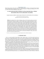
For this purpose, two-input one-output fuzzy system is
designed whose inputs are s and s which are the distances
of the state trajectories to the sliding surface and its
derivative, respectively. The membership functions of these
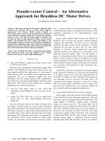
two inputs are shown in figure (1). The output of the fuzzy
system is denoted by K fuzz and has been shown in figure
K = N ⋅ K fuzz
(20)
K v = N v ⋅ K fuzz
(21)
These factors can be selected by trial and error such that the
stability condition (17) is satisfied.
Degree of membership
NSZEPS
PB
0.8
0.6
0.4
-0.5
0
input variable "s"
0.5
1
(a)
Fig. 1: The membership functions for a) input
0.5
1
S
Degree of membership
1
M
s
B
0.8
0.6
0.4
0.2
0
0
0.2
0.4
0.6
output variable K
0.8
1
Fig. 2: The membership functions of the output
Tab. 1: The fuzzy rule base for tuning
s
s
N
Z
P
K fuzz
K fuzz
NB
NS
Z
PS
PB
B
B
B
B
M
S
M
S
M
S
M
B
B
B
B
The maximum values of K and Kv are limited according to
the system actuators power, and the minimum value of K
should not be less than the provided amount in relation (17).
The fuzzy base rule has been given in table (1) in which the
following abbreviations have been used: NB: Negative Big;
NS: Negative Small; Z: Zero; PS: Positive Small; PB:
Positive Big; M: Medium. For example, when s is negative
small (NS) and s is positive (P), then K fuzz is small (S).
THE CASE STUDY AND SIMULATION
RESULTS
In order to show the effectiveness of the proposed control
law, it is applied to two-links robot with the following
parameters:
0
-1
0
inpu variable sd
(b)
5
0.2
-0.5
Continue Fig. 1: The membership functions for b) input
(2). For applying these gains to the control input, the
normalization factors N and N v as the following relations
are used:
NB
P
0.8
THE DESIGN OF FUZZY SMC-PID
1
Z
(19)
By this, there is a boundary layer ϕ around the sliding
surface such that when the state trajectory reach to this layer
will be remaining there.
4
N
1
Degree of membership
sat
s
s
M (q) =
C ( q, q ) =
α + β + 2γ cos q 2
β + γ cos q 2
β + γ cos q 2
β
− γq 2 sin q 2
− γ (q1 + q 2 ) sin q 2
γq1 sin q 2
0
(22)
(23)
αδ 1 cos q1 + γδ 1 cos(q1 + q 2)
γδ 1 cos(q1 + q 2 )
(24)
150
input1(N.m)
G (q) =
where α = (m1 + m2 )a12 , β = m 2 a 22 , γ = m 2 a1 a 2 ,
δ = g a 1 , and m1 , m 2 , a1 = .7 , a 2 = .5 are the masses
and lengths of the first and second links, respectively. The
masses are assumed to be in the end of the arms and the
gravity acceleration is considered g = 9.8 . Moreover, the
masses are considered with 10% uncertainty as follow:
,
∆m1 ≤ .4
m 2 = m 20 + ∆m 2
,
∆m 2 ≤ .2
50
0
-50
0
2
4
6
8
10
6
8
10
time(sec)
100
input2(N.m)
m1 = m10 + ∆m1
100
(25)
50
0
-50
where m10 = 4 and m 20 = 2 , and Mˆ , Cˆ , and Gˆ are
0
2
4
time(sec)
estimated. The desired state trajectory is:
Fig. 4: The control inputs in the case of using conventional SMC
1 − cos π t
(26)
2 cos π t
0.15
and the disturbance torque is considered as follows:
τd =
(27)
0.5 sin 2πt
0.5
.
0.5
The
values
15
0
0
, λ2 =
15
40
the ϕ and η
of
0
0
2
4
0
0
(28)
40
are
selected
as
0
2
4
5 0
0 10
(29)
Error1(rad)
200
100
0
-100
0
2
4
6
8
10
6
8
10
time(sec)
100
50
0
-50
-100
0.1
0.05
0
2
4
time(sec)
0
0
2
4
6
8
10
time(sec)
2
Error2(rad)
10
time(sec)
input1 (N.m)
Nv =
0.15
1.5
1
0.5
0
-0.5
8
0
Fig. 5: The tracking errors in the case of using Fuzzy SMC-PID
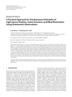
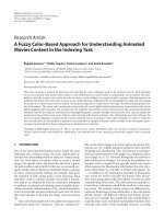
In order to show the improvement due to the proposed
method of this paper (Fuzzy SMC-PID), the simulation
results of applying this method are compared with the
related results of the conventional SMC. The tracking error
and control law in the case of conventional SMC have been
shown in figures (3) and (4), respectively. The
corresponding graphs for the case of applying fuzzy
SMC-PID are also provided in figures (5), and (6).
-0.05
6
1
0.5
-0.5
input2 (N.m)
,
10
2
and N v are selected as follow:
50 0
0 5
8
1.5
ϕ = 0.167 and η = [0.1 0.1]T . Moreover, the factors N
N=
6
time(sec)
The design parameters are determined as follow:
λ1 =
0.1
0.05
-0.05
Error2 (rad)
which leads to TD =
0.5 sin 2πt
Error1(rad)
qd =
0
2
4
6
8
10
time(sec)
Fig. 3: The tracking errors in the case of using conventional SMC
Fig. 6: The control inputs in the case of using Fuzzy SMC-PID
As it is seen in these figures, the proposed fuzzy SMC-PID
has faster response and less tracking error in comparison
with conventional SMC. In order to show more clearly the
difference between the tracking errors in two cases, the
enlarged graphs have been provided in figures (7) and (8).
Error1(rad)
0.01
0.005
0
-0.005
-0.01
0
2
4
6
8
10
6
8
10
time(sec)
-3
x 10
Error2(rad)
5
0
-5
0
2
4
time(sec)
Fig. 7: The enlargement of the tracking errors in the case of using
conventional SMC
-4
Error1 (rad)
5
x 10
0
-5
0
2
4
6
8
10
6
8
10
time(sec)
-3
Error2 (rad)
1
x 10
0.5
0
-0.5
-1
0
2
4
time(sec)
Fig. 8: The enlargement of the tracking errors in the case of using
Fuzzy SMC-PID
6
CONCLUSION
In this paper, design of a sliding mode control with a PID
loop for robot manipulator was presented in which the gain
of both SMC and PID was tuned on-line by using fuzzy
approach. Then the stability guarantee of the system was
proved by direct Lyapunov method. The proposed
methodology in fact tries to use the advantages of the SMC,
PID and Fuzzy controllers simultaneously, i. e., the
robustness against the model uncertainty and external
disturbances, quick response, and on-line automatic gain
tuning, respectively. Finally, the simulation results of
applying the proposed methodology to a two-link robot
were provided and compared with corresponding results of
the conventional SMC which show the improvements of
results in the case of using the proposed method.
REFERENCES
[1] M. W. Spong, and M. Vidiasagar, Robot Dynamics and
Control, Wiley, New York, 1989.
[2] J. J. Slotine, and W. Li, Applied Nonlinear Control,
Englewood Cliffs, NJ: Prentice Hall, 1991.
[3] W. Perruquetti, and J. P. Barbot, Sliding Mode Control in
Engineering. Marcel Dekker, Inc. New York, 2002.
[4] J. Y. Hung, W. Gao, and J. C. Huang, Variable Structure
Control: A Survey, IEEE Trans. Ind. Elec., Vol. 40, No. 1,
2-22, 1993.
[5] L. X. Wang, A Course in Fuzzy Systems and Control,
Prentice Hall, NJ, 1997.
[6] C. C. Lee, Fuzzy Logic in Control Systems: Fuzzy Logic
Controller-Part I, IEEE Trans. Sys. Man. and Cyb. Vol. 20,
No. 2, 404-418, 1990.
[7] C. C. Lee, Fuzzy Logic in Control Systems: Fuzzy Logic
Controller-Part II, IEEE Trans. Sys. Man. and Cyb. Vol. 20,
No. 2, 419-435, 1990.
[8] R. Palm, D. Driankov, and H. Hellendoorn, Model Based
Fuzzy Control: Fuzzy Gain Schedulers and Sliding mode
Fuzzy Controllers. Springer-Verlag Berlin Heidelberg, 1997.
[9] J. C. Lo, and Ya. H. Kuo, Decoupled Fuzzy Sliding Mode
Control, IEEE Trans on Fuzzy systems, Vol. 6, No. 3,
426-435, 1998.
[10] L. K. Wang, H. F. Leung, and K. S. Tam, A Fuzzy Sliding
Controllers for Nonlinear Systems, IEEE Trans. Ind. Elec.,
Vol. 48, No. 1, 32-37, 2001.
[11] Q. P. Ha, Q. H. Nguyen, D. C. Rye, and H. F. Durrant-Whyte,
Fuzzy Sliding Mode Controllers with Applications, IEEE
Trans. Ind. Elec., Vol. 48, No. 1, 38-46, 2001.
[12] Z. Lin, Q. Zhu, and Y. Yan, Variable Structure Control Based
on Fuzzy Law for Underactuated Robot Manipulators, IEEE
Int. Conf. on Mechatronics and Automation, 1908-1913,
2006.
[13] C. M. Lin, and Y. J. Mon, Decoupling Control by Hierarchical
Fuzzy Sliding Mode Controller, IEEE Trans. Cont. Sys.
Technology, Vol. 13, No. 4, 593-598, 2005.
[14] Y. C. Huang, and T. H. S. Li, Fuzzy Terminal Sliding Mode
Controller for Robotic Manipulators, IEEE Int. Conf. on
Mechatronics, 858-863, 2005.
[15] Q. P. Ha, D. C. Rye, and H. F. Durrant-Whyte, Fuzzy Moving
Sliding Mode Control with Application to Robotic
Manipulators, Automatica, Vol. 35, 607-616, 1999.
[16] H. Javaheri, and G. R. Vossoughi, Sliding Mode Control with
Online Fuzzy Tuning: Application to a Robot Manipulator,
IEEE Int. Conf. on Mechatronics & Automation, 1357-1362,
2005.
[17] T. C. Kuo, Y. J. Huang, A Sliding mode PID-Controller
Design for Robot Mnipulator, IEEE Conf. On Computational
Intelligence in Robotics and Automation, 625-629, 2005.
[18] I. Eker, Sliding mode control with PID sliding surface and
experimental application to an electromechanical plant, ISA.
Trans. Vol. 45, No. 1, 109-118, 2006.