An investigation of fractiure criteria for predicting serface fracture in paste extrusion
Bạn đang xem bản rút gọn của tài liệu. Xem và tải ngay bản đầy đủ của tài liệu tại đây (818.51 KB, 30 trang )
International Journal of Mechanical Sciences 44 (2002) 1381 – 1410
An investigation of fracture criteria for predicting surface
fracture in paste extrusion
Annette T.J. Domantia , Daniel J. Horrobinb , John Bridgwatera; ∗
a
Department of Chemical Engineering, University of Cambridge, Pembroke Street, Cambridge, CB2 3RA, UK
b
Department of Mathematics & Statistics, The University of Melbourne, VIC 3010, Australia
Received 27 February 2001; received in revised form 20 May 2002
Abstract
In the extrusion of pastes, fractures may be found on the surface of product. Such fractures compromise
strength and are often unacceptable aesthetically. Here some theoretical criteria for predicting the onset of
surface fracture, using the elastic–plastic ÿnite element method are evaluated and the success of these criteria
in predicting recent observations is assessed. Two criteria based on stress ÿelds successfully predicted an
increase in the depth of fracture cracks with extrusion ratio. However these criteria, which are dependent
on the deforming zone stresses and extrudate residual stresses, respectively, do not successfully predict the
increase in fracture with increasing die entry angle observed experimentally. Three criteria based on ductile
fracture are also investigated and di culties associated with their accurate evaluation in extrusion problems
highlighted. However, all three successfully predict the increase in fracture with increasing die entry angle. In
considering the e ect of extrusion ratio on surface fracture, two of these criteria should be at least qualitatively
correct while for the third this is unlikely.
? 2002 Elsevier Science Ltd. All rights reserved.
Keywords: Paste; Surface fracture; Extrusion; Defects; Fracture criteria; Modelling; ABAQUS
1. Introduction
Extrusion has long been used in the metals industry to make bars, tubes, wires and strips with
signiÿcant attempts being made to describe its occurrence in fundamental terms. Polymer extrusion
is of enormous industrial signiÿcance and commands a very substantial literature on the origins of
a wide range of surface instabilities but the origin of the behaviour of important materials such
as high-density polyethylene remains very incomplete. Pastes consist of mixtures of ÿne powders
∗
Corresponding author. Tel.: +44-1223-334798; fax: +44-1223-334796.
E-mail address: john (J. Bridgwater).
0020-7403/02/$ - see front matter ? 2002 Elsevier Science Ltd. All rights reserved.
PII: S 0 0 2 0 - 7 4 0 3 ( 0 2 ) 0 0 0 4 7 - 4
1382
A.T.J. Domanti et al. / International Journal of Mechanical Sciences 44 (2002) 1381 – 1410
Nomenclature
CL
D0
D
E
GW
H
p
P
R
r
si
t
vi
Y
z
Cockcroft and Latham fracture integral (N m−2 )
Barrel diameter (m)
die diameter (m)
Young’s modulus (N m−2 )
generalised work fracture integral (N m−2 )
hybrid fracture integral (N m−2 )
pressure (negative average normal stress) [ 13 ( 1 + 2 + 3 )] (N m−2 )
extrusion pressure (N m−2 )
extrusion ratio [D02 =D2 ] (dimensionless)
radial coordinate in cylindrical polar system (m)
deviatoric normal stress component (i = r, Â or z or 1, 2 or 3) [ i + p] (N m−2 )
time (s)
velocity component (i = r or z) (m s−1 )
uniaxial yield stress (N m−2 )
axial coordinate in cylindrical polar system (m)
Greek letters
˙i
normal strain rate component (i = r, Â or z or 1, 2 or 3) (s−1 )
˙
equivalent strain rate [ 2=3( ˙21 + ˙22 + ˙23 )1=2 ] (s−1 )
˙rz
shear strain rate component in the r–z plane (s−1 )
˙
non-negative scalar describing the magnitude of the plastic strain rate (N−1 m2 s−1 )
Poisson’s ratio (dimensionless)
Â
angular coordinate in cylindrical polar system (m)
dimensionless radial coordinate (dimensionless)
stress
component (either normal, in which case i=j, or shear, in which case i = j) (N m−2 )
ij
normal stress component (i = r, Â or z or 1, 2 or 3) (N m−2 )
i
shear stress component in the r–z plane (N m−2 )
rz
!
rate of rotation of a material element (s−1 )
Subscripts
1
major principal component
2
intermediate principal component
3
minor principal component
r
radial component
Â
circumferential component
z
axial component
Superscripts
◦
Jaumann stress rate (corrected for rotational motion)
·
material stress rate (corrected for linear motion)
A.T.J. Domanti et al. / International Journal of Mechanical Sciences 44 (2002) 1381 – 1410
1383
Extrusion direction
· 6 mm
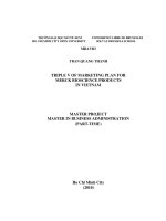
Fig. 1. Surface fracture for an alumina paste extrudate [1].
and complex liquids which, during extrusion, are subject to a range of ow conditions. Shaping by
paste extrusion now forms an important route for manufacturing an ever-increasing number of common materials including foods, chemicals, catalyst substrates and pharmaceutics, as well as engine
parts made from advanced materials, but the literature is sparse. During extrusion, imperfections
in the quality of the extrudate may arise, ranging from a rough or uneven surface to a complete
severance of the extrudate. Historically a trial-and-error method has been used for forming extrusion
products of su cient quality, a costly, uncertain and time-consuming practice. The ability to identify and predict these defects is crucial to modern practice and is challenging fundamentally. Small
external or internal defects may also be potential sources of weakness in the ÿnal product.
Fig. 1 shows a ceramic alumina paste formed into a long rod by extrusion from a cylindrical barrel
of 25 mm diameter through an axisymmetric die of square entry with diameter 6 mm and die land
length 2 mm, the system studied by Domanti and Bridgwater [1]. The most noticeable feature is the
presence of regular breaks in the surface, roughly encircling the extrudate and therefore described
as circumferential cracks. Such surface fracturing is an example of an extrusion defect, which may
compromise the strength and performance of the extruded product.
Similar surface fracture has been observed for various materials other than ceramic pastes. For
example, Domanti and Bridgwater also discuss surface fracturing in the extrusion of soap. The
phenomenon is well known in the industry but the sole study in which some of the important
parameters are varied systematically is the recent one of these two workers. Although pastes may
contain two or more phases, processing is carried out under conditions such that the phase separation
is minimal and the material overall exhibits a yield stress. Thus it is in metal forming where related
phenomena have been examined, where several explanations for its cause have been proposed, along
with criteria for predicting its occurrence. Hence the present purpose is to examine criteria that have
appeared in the metal forming literature and to evaluate how well these predict the experimental
observations of Domanti and Bridgwater.
1.1. Theoretical approaches to fracture
Fracturing of solids occurs in many situations, and theories for describing phenomena have been
extensively developed during the last century. Conventional fracture mechanics [2,3] deals with
macroscopic cracks in bodies that would often otherwise be loaded to within their elastic limit. By
examining the stress and deformation ÿelds in the vicinity of the crack, it is determined whether the
crack will grow, resulting in fracture.
1384
A.T.J. Domanti et al. / International Journal of Mechanical Sciences 44 (2002) 1381 – 1410
In contrast, when investigating defects that arise in forming processes, it is not usual to assume pre-existing macroscopic cracks in the workpiece. Instead, strategies for predicting defects
have been based on the stress and=or deformation histories of the entire, initially uncracked body,
which inevitably undergoes substantial inelastic deformation forming. Among those adopting this
approach are Clift et al. [4], Ko et al. [5], and DeLo and Semiatin [6]. The ÿrst of these is
particularly extensive, investigating nine di erent ductile fracture criteria applied to three di erent
metal-forming operations, of which extrusion is one. Two of these, the Generalised Work Criterion
and the Cockcroft and Latham Criterion, are two of the three ductile fracture criteria discussed
here.
At the heart of a typical calculation procedure is a numerical, usually ÿnite element, model that
takes information about (i) the geometry of the die and workpiece, (ii) operating variables such
as temperature and the rate of deformation, and (iii) the bulk constitutive response of the material
and the interaction with solid boundaries. The stresses and strains are then calculated as functions
of time from which predictions regarding the occurrence of fracture are obtained. This procedure
has been followed here, although temperature and deformation rate are not involved, as we have
assumed that the extrusion process is isothermal, an excellent assumption for pastes. The material is
described by a perfect plasticity model with Tresca boundary conditions.
This bears some resemblance to a continuum damage mechanics analysis. It is widely believed
that on a microscopic level, fracture in metals occurs by nucleation, growth and coalescence of
voids. 1 Damage mechanics [8] seeks to model the overall e ect of an evolving population of such
microdefects through a macroscopic ‘damage’ variable, or variables, that can be loosely interpreted as
a porosity. A law is introduced that describes how the damage changes with time in response to the
local stress and deformation ÿelds. This law may be based on micromechanical arguments, or may
be postulated without detailed reference to the microstructure. An analysis is then performed similar
to that above, in the sense that the existence of macroscopic cracks is not assumed, and the stress,
strain and damage histories are computed throughout the specimen. The damage accumulates until
the material is said to have lost all structural integrity, or at least the appearance of a macroscopic
crack is predicted. However, the key di erence between a typical damage mechanics analysis and
the calculations here is that the former takes into account the e ect on the overall mechanical
properties, such as Young’s modulus and yield stress, of the growing microdefects. Rather than
the one-way coupling between the stress=strain history calculation and the fracture calculation, a
more complicated, fully coupled analysis is performed. Such analyses have become increasingly
popular in recent years for investigating a range of failure phenomena that arise in solid mechanical
applications [9].
1.2. The current work
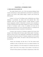
A schematic diagram of a ram extruder used to produce the extrudate in Fig. 1 is shown in Fig. 2.
The die comprises two sections: (i) the die entry, the region where deformation occurs immediately
upstream from the re-entrant corner, and (ii) the die land, the parallel-sided section downstream
1
Similar void growth has been observed in deforming Plasticine [7], a dispersion of clay particles in mineral oil that
is often used as a model material for studying metal-forming processes, and which is perhaps not dissimilar to a ceramic
paste.
A.T.J. Domanti et al. / International Journal of Mechanical Sciences 44 (2002) 1381 – 1410
1385
Fig. 2. A simple ram extruder with a conical entry die.
from that corner. Outside the die entry, both upstream in the barrel and downstream in the die land,
the material is essentially rigid; pastes and other soft solids observed slip at solid boundaries. A
conical entry is shown in the ÿgure, the entry angle being that the die face makes with the axial
◦
direction. For a square entry die, the entry angle is 90 so the die face is perpendicular to the
axial direction and the contraction is abrupt. The other parameter used to deÿne geometry is the
reduction in cross-sectional area, expressed as an extrusion ratio deÿned as the ratio of the ÿnal to
the initial cross-sectional area or the square of the diameter ratio, if both barrel and die-land are
circular.
We evaluate the e ect of the die entry geometry on the level of fracture. The key conclusions
from Domanti and Bridgwater relevant to this objective are:
(i) the level of fracture decreases with increasing extrusion ratio, for extrusion ratios in the range
4.34 – 69.4, and
◦
(ii) the level of fracture increases with increasing entry angle, for entry angles in the range 15 –45 ,
◦
and remains reasonably constant for entry angles above 45 .
The term ‘level of fracture’ refers primarily to the depth of cracks in the extrudate relative to the
extrudate diameter since the frequency (i.e. spacing of cracks) was found to be equal to the extrudate
radius for all entry angles and reduction ratios.
A commercial ÿnite element package (ABAQUS) is used to simulate the extrusion of a paste
using an elastic–plastic material model. This provides the detailed information about the stresses and
strains within the deforming material required for evaluation of the fracture criteria. Two classes of
fracture criteria are considered:
(i) those based on the current stress ÿeld alone, and
(ii) those based on the entire stress and deformation histories.
The ÿrst class is often regarded as being appropriate for describing brittle fracture, and the second
class for describing ductile fracture.
Here, the ÿrst class is represented by the hypotheses of Pugh (presented in Pugh and Green [10],
Pugh and Gunn [11], and Pugh [12], and Fiorentino et al. [13]). These hypotheses were developed
to explain cracking in extrusion of brittle metals such as bismuth, magnesium and beryllium. Pugh
suggested that cracking resulted from insu cient compressive stress in the deforming zone, while
Fiorentino et al. argued that the cause lay with tensile residual stresses.
1386
A.T.J. Domanti et al. / International Journal of Mechanical Sciences 44 (2002) 1381 – 1410
We examine three ductile fracture criteria: the Generalised Work and Cockcroft and Latham criteria
considered by Clift et al. [4], and a new one that can be viewed as a combination of the ÿrst two,
which we call the Hybrid Criterion. In all three cases, the rate of change of damage in a material
element is given by a quantity that has dimensions of rate of energy dissipation per unit volume. For
the Generalised Work Criterion, this quantity is simply the usual expression for the rate of energy
dissipation per unit volume in a deforming material, 1 ˙1 + 2 ˙2 + 3 ˙3 , which does not distinguish
between energy dissipated under tensile and compressive stresses. The other two use some measure
of the rate of energy dissipation in the presence of tensile stresses alone.
2. Model
It is widely recognised that pastes with a wide range of formulations exhibit a yield stress, or at
least an apparent yield stress, and thus a plasticity-based model is appropriate. The stresses within
a deforming paste also can exhibit a dependence on strain rate, which is neglected here. However,
ceramic pastes of the type studied by Domanti and Bridgwater show little rate dependence. The
details of the plastic response of typical pastes, i.e. the yield criterion and ow rule followed, remain
largely unresolved. For this work, the von Mises yield criterion and associated ow rule have been
adopted, mainly for reasons of convenience. However, experiments with various solid metals [14,15]
indicate that the von Mises criterion and its associated ow rule describe deformations rather better
than the Tresca criterion and its associated ow rule. In the absence of alternative information, it is
reasonable to assume pastes behave in a similar way.
If the predominantly plastic nature of paste ow is widely accepted, the response below the yield
point is much less clear. It is often assumed that when subjected to small stresses the material
deforms elastically, with Young’s modulus that is large compared with the yield stress, so that
the elastic strains are always small. This is analogous to the behaviour of solid metals, ignoring
the phenomenon of creep. The elastic–plastic approach is followed here, with the elastic response
described by the linear Hookean model. 2 The combined uniaxial stress–strain relationship therefore
has a very simple form, with the stress being proportional to strain until the yield point is reached,
and being constant thereafter.
In addition to the constitutive model, the usual force equilibrium relationships of continuum mechanics are required. For paste ows, as in metal forming, body forces are usually neglected; typical
ow velocities are small enough for inertial e ects to be insigniÿcant, and the yield stress is usually large enough for gravitational e ects to be ignored. To illustrate how they are written for an
axisymmetric problem, the equations underlying the model are listed in Table 1. Further details can
be found in standard texts, e.g. [17]. The rest of the formulation concerns the boundary conditions
at solid surfaces. Unlike viscous uids, elastic and=or plastic solids are usually regarded as being
capable of slipping at such surfaces. In the theory of metal forming, a Coulomb friction boundary
condition is thought to be most realistic. However, this is sometimes substituted, for computational
2
An alternative formulation for numerical plastic ow calculations exists, where the material is e ectively treated as a
highly viscous uid below the yield point [16]. This formulation, which has some computational advantages, was developed
to approximate the true behaviour of solid metals. However, for pastes and other soft solids it may prove to be more
realistic than the elastic–plastic model.
A.T.J. Domanti et al. / International Journal of Mechanical Sciences 44 (2002) 1381 – 1410
1387
Table 1
Equations of motion for an axisymmetric problem referred to an Eulerian cylindrical polar coordinate system
Basic equations
Force equilibrium equations (body forces neglected):
@ r
@ rz
r − Â
+
+
=0
@r
@z
r
@ z
@ rz
rz
+
+
=0
@z
@r
r
Von Mises yield criterion:
(
r
−
Â)
2
+(
Â
−
z)
2
(1a)
+(
z
−
r)
2
2
rz
+6
6 2Y 2
(1b)
Prandtl–Reuss ow rule, incorporating Hooke’s Law and the von Mises associated ow rule:
1
( ˙r −
E
1
˙0 = ( ˙Â −
E
1
˙z = ( ˙z −
E
1+
˙rz =
˙rz
E
˙r =
˙Â − ˙z ) + (2
r
−
Â
−
z)
˙;
˙z − ˙r ) + (2
Â
−
z
−
r)
˙;
˙r − ˙Â ) + (2
z
−
r
−
Â)
˙;
+3
rz
˙:
(1c)
Notes regarding the ow rule:
(i) The stress and strain rates must correspond to real material deformation, and must therefore vanish in the case of
rigid body motion. ˙ij is the true strain rate with components
˙r =
@vr
;
@r
◦
where
◦
r
ij
˙Â =
vr
;
r
˙z =
@vz
;
@z
˙rz =
1
2
@vr
@vz
+
@z
@r
:
(1d)
is the Jaumann stress rate with components
= ˙r − 2
◦
rz !;
Â
◦
= ˙Â ;
z
= ˙z + 2
◦
rz !;
rz
= ˙rz + (
r
−
z )!;
(1e)
where ! is the rate of rotation of a material element
!=
1
2
@vr
@vz
−
@z
@r
(1f)
and ˙ij is the material stress rate
˙ij =
@ ij
@ ij
@ ij
+ vr
+ vz
:
@t
@r
@z
(1g)
(ii) ˙ is a non-negative scalar describing the magnitude of the plastic strain rate. It is zero where the yield criterion
(1b) is satisÿed as a strict inequality (below the yield point), and can be non-zero if (1b) is satisÿed as an equality
(at the yield point).
Strictly speaking, ˙ can only be non-zero if the material is at the yield point and the rate of change of stress is
such that it remains at the yield point. The latter condition can be expressed mathematically by di erentiating (1b)
(
r
−
◦
 )( r
−
◦
Â)
+(
Â
−
◦
z )( Â
− ˙z ) + (
z
−
◦
r )( z
−
◦
r)
+6
◦
rz rz
= 0:
(1h)
1388
A.T.J. Domanti et al. / International Journal of Mechanical Sciences 44 (2002) 1381 – 1410
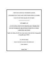
Fig. 3. Example ÿnite element mesh showing variation in element size and rounding at re-entrant corner.
convenience, by a Tresca boundary condition, where the wall shear stress is constant, provided the
material is slipping or on the point of slipping. This parameter is usually expressed as a fraction
of the shear yield stress of the material. For pastes, which are solid–liquid mixtures, a liquid-rich
layer is thought to form where slip occurs at a surface, which then lubricates the interior ow.
Depending on the rheology of this layer, the wall shear stress may then be approximately constant
(the Tresca condition), or may increase from zero as the slip velocity increases. More generally,
it may combine both features, increasing with slip velocity from an initial non-zero value. We
have chosen to use the simplest Tresca boundary condition, where the wall shear stress is zero,
corresponding to a well-lubricated interface; this is a reasonable approximation for ceramic pastes
studied.
3. Solution procedure
The equations of motion were solved using the ABAQUS ÿnite element package, version 5.5
(Hibbitt, Karlsson and Sorensen, Inc., 1995). As the problems considered here were all axisymmetric,
two-dimensional meshes, covering the radial and longitudinal directions, were used. These meshes
were constructed from irregular quadrilateral elements with widely varying sizes, small and large
elements being employed in regions where the rates of strain were large and small, respectively.
A typical mesh, in this case for a square entry die, is shown in Fig. 3. The smallest elements are
required near the die corners, especially the re-entrant corner. The corners are also rounded slightly,
and the local element size is chosen to be slightly smaller than the ÿllet radius at the corner. The
ÿllet radius is a small proportion (typically around 1%) of the barrel radius, and so the solution
obtained from the analysis is expected to be close to the solution for a die with perfectly sharp
corners. Using meshes of the form shown in Fig. 3, the solutions were found to be insensitive to
the precise details of the mesh construction.
Young’s modulus was chosen to be two or three orders of magnitude larger than the uniaxial yield
stress so that elastic strains were small, and the solution corresponded closely that for the rigid-plastic
limit. Here the stresses in the deforming material should not be sensitive to the precise values of
Young’s modulus and Poisson ratio. However, a value for the Poisson ratio must be speciÿed, the
value selected, somewhat arbitrarily, being 0.49. This is close to 1=2, and so the elastic component
A.T.J. Domanti et al. / International Journal of Mechanical Sciences 44 (2002) 1381 – 1410
1389
of the deformation is at approximately constant volume; the plastic component is constant volume.
It might be anticipated that even with a large Young’s modulus to yield stress ratio, the stresses
outside the deforming region could still be sensitive to the Poisson ratio. This could be important
since we need the residual stress ÿeld in the extrudate when we come to the hypothesis of Fiorentino
et al. However, when duplicate analyses were carried out for a square entry die with extrusion ratio
9.77, using Poisson ratios of 0.49 and 0.10, the di erences in the residual stress ÿelds were found to
be insigniÿcant. Similarly, duplicate analyses for the same die geometry with Young’s moduli 400
times and 1000 times the uniaxial yield stress produced no signiÿcant di erences.
ABAQUS implements an updated Lagrangian ÿnite element formulation where, as the calculation
proceeds, the mesh deforms following the deformation of the material. This causes di culty when
the deformation is large, as in the problems studied here, since the elements quickly become grossly
distorted leading to errors. This was overcome by rezoning at frequent intervals. In this procedure,
when the distortion has increased to an unacceptable level, the calculation was stopped. A new mesh,
comprising well-shaped elements, is then constructed within the boundary of the old mesh, and the
current solution is mapped from the old mesh to the new mesh. The calculation is then restarted
using the mapped solution to provide the initial conditions for the new analysis step. The rezoning
procedure also enables small elements to be retained in the regions where the rate of strain is large,
and large elements in regions where the rate of strain is small. Further information regarding the
procedure can be found in Ref. [18] and in more detail in Ref. [19].
4. Results: deforming zone stresses
Pugh and Gunn [11], as reported by Pugh and Low [20], suggested that the cause of surface
fracture was the insu ciency of the ‘total hydrostatic compressive stress existing in regions in
which the material is being deformed’. Experiments to test this hypothesis were carried out by Pugh
and Gunn, and earlier by Pugh and Green [10]. They extruded brittle metals with apparatus that
allowed the extrudate to emerge into a pressurised liquid, and determined the uid back pressure
required to suppress surface cracking. Pugh’s hypothesis is examined, using results from the ÿnite
element calculations.
4.1. Implementation
In the absence of detailed information about the stress ÿeld in the deforming material, Pugh
suggested that a rough measure of the hydrostatic compressive stress in the deforming zone was
the average stress on the die face, calculated as the extrusion load divided by the area of contact
between the billet and die (i.e. die face area). This quantity has been determined. Finite element
analyses allow the stress ÿeld in the deforming material to be investigated in more detail, and hence
several alternative interpretations of ‘total hydrostatic compressive stress’ are possible. For example,
this term could refer to:
• the volume average pressure in the deforming material (where the pressure at a point is the
negative average of the normal stress components), or
• the maximum pressure in the deforming material.
1390
A.T.J. Domanti et al. / International Journal of Mechanical Sciences 44 (2002) 1381 – 1410
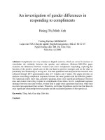
Fig. 4. Deforming zone as deÿned by integration points where there is active yielding.
These two possibilities are also examined. In either case, it is necessary to have a suitable deÿnition
of ‘deforming material’, and we have taken it to be the region where the plastic strain rate is non-zero.
In ABAQUS, a ag variable is used to label element integration points as ‘actively yielding’ if the
plastic strain increment is non-zero during a given analysis increment, and this provides a convenient
way to identify the deforming zone.
Fig. 4 shows the locations of the actively yielding integration points for a single increment in an
analysis for a square entry die with barrel diameter 25 mm and die diameter 8 mm. The integration
points are particularly closely spaced near the re-entrant corner, where the elements are small to
accommodate the high strain rates that occur there, and some integration points in this vicinity have
been omitted for clarity.
A fourth stress quantity that has been examined, namely the extrusion pressure. This is a somewhat
loose interpretation of ‘average hydrostatic compressive stress in the deforming zone’, but has the
advantage of convenience, as it is the most likely stress parameter to be recorded.
4.2. E ect of extrusion ratio
Square entry dies: Analyses were performed for extrusion through square entry dies with barrel
diameter 25 mm and die diameters between 2 and 24 mm, corresponding to extrusion ratios between
156 and 1.09. Fig. 5 shows the maximum and average deforming zone pressures, the average die face
pressure and the extrusion pressure, all plotted against the extrusion ratio. The latter two pressures
have been plotted from results given in Ref. [18], and are not strictly average pressures, but rather
average stresses normal to the die face and ram, respectively.
A.T.J. Domanti et al. / International Journal of Mechanical Sciences 44 (2002) 1381 – 1410
1391
Fig. 5. Various measures of pressure versus extrusion ratio for square entry dies.
According to Pugh’s hypothesis, a higher level of fracture is expected when the average hydrostatic
compressive stress in the deforming zone is small. The average deforming zone pressure and the
extrusion pressure both increase monotonically with extrusion ratio R, while the maximum deforming
zone pressure and the average die face pressure both exhibit minima when R is about 2 to 3.
Considering that the maximum deforming zone pressure occurs at the die face for smooth-walled
dies, it is not surprising that this quantity is closely related to the average die face pressure. The
pressure increases when R is small and decreasing, indicating that as R tends to zero the extrusion
pressure approaches zero more slowly than the die face area approaches zero.
Pugh [12], discussing the magnesium rod extrusions carried of Pugh and Gunn [11], also identiÿed
a minimum in the average die face pressure. He suggested that where the minimum occurs at
around R = 2, large back pressures would be required to prevent surface fracture. Equivalently, when
extruding into atmospheric pressure, the level of fracture would be expected to be highest at around
R = 2.
The paste extrusion experiments indicated that the relative depth of fracture increases with die
diameter in the range D = 3–12 mm, or equivalently decreases with increasing extrusion ratio in the
range R = 4:34– 69.4. This correlates well with the increase in all four quantities plotted in Fig. 5
when the extrusion ratio is large and increasing. At present, no experimental results are available
for smaller extrusion ratios. Such data would allow the suitability of the di erent deforming zone
pressures to be better assessed, and Pugh’s hypothesis to be interrogated more thoroughly.
◦
45 tapered entry dies. Analyses were also performed for extrusion through tapered entry dies with
◦
45 entry angles, barrel diameter 25 mm and die diameters between 8 and 20 mm, corresponding
1392
A.T.J. Domanti et al. / International Journal of Mechanical Sciences 44 (2002) 1381 – 1410
Fig. 6. Various measure of pressure versus entry angle for dies with extrusion ratio R = 4:34.
to extrusion ratios between 9.77 and 1.56. These produced very similar relationships between the
deforming zone pressures and extrusion ratio. The conclusions are thus similar.
4.3. E ect of taper angle
Analyses were performed for extrusion through tapered entry dies with barrel diameter 25 mm,
◦
die diameter 12 mm (corresponding to an extrusion ratio 4.34), and seven entry angles between 5
◦
and 90 . Fig. 6 shows the four dimensionless pressures plotted against entry angle for these dies.
The extrusion pressure and average die face pressure are again based on Ref. [18]. Some scatter
is apparent in the maximum deforming zone pressures, re ecting the di culty of determining this
quantity accurately. These points relate to single outlying stress values, whereas the other quantities
are all a ected by many stress values. The general trend exhibited by all four quantities, however,
◦
◦
is of a moderate increase with entry angle as the entry angle increases from 5 to 90 .
Applying Pugh’s hypothesis to these results suggests that smaller entry angles are more likely to
give rise to fracture. This contradicts the experimental results of Domanti and Bridgwater. None of
the four pressure quantities shows a clear decrease with increasing entry angle, and so in this case
Pugh’s hypothesis appears to fail. However, Pugh appreciated that the e ect of entry angle had not
been adequately incorporated into the theory.
5. Results: extrudate residual stresses
Fiorentino et al. [13] suggested that the longitudinal stress at the extrudate surface determines
whether the material will fracture, fracture being associated with a tensile value. Both Osakada et al.
[21] and Polyakov et al. [22] experimentally evaluated stresses in metal extrudates and found that
these were tensile at the surface and compressive in the centre. Rudkins et al. [23] performed ÿnite
element analyses that supported the hypothesis of Fiorentino et al.
A.T.J. Domanti et al. / International Journal of Mechanical Sciences 44 (2002) 1381 – 1410
1393
Fig. 7. Calculated longitudinal stress versus radial coordinate for square entry dies with various extrusion ratios: (a) larger
extrusion ratios; and (b) smaller extrusion ratios.
5.1. E ect of extrusion ratio
Square entry dies. Fig. 7 shows the longitudinal stress in the die land as a function of the
radial coordinate (made dimensionless dividing by the die land radius) for six of the 12 extrusion ratios examined. For clarity the curves are plotted on two separate diagrams: Fig. 7(a) shows
the results for the three larger extrusion ratios, and Fig. 7(b) the results for the three smaller extrusion ratios. The values were obtained by averaging in the longitudinal direction within the die
land; the stresses are observed to vary little in this direction. The results can be summarised as
follows:
• For the largest extrusion ratios (R = 156 and 9.77) the longitudinal stress proÿle is approximately
linear, with the stress being compressive (negative) on the axis and tensile at the surface. Both
1394
A.T.J. Domanti et al. / International Journal of Mechanical Sciences 44 (2002) 1381 – 1410
Fig. 8. Surface longitudinal stress versus extrusion ratio for square entry dies.
central and surface stresses increase in magnitude as R decreases, although the proÿle for R = 6:25
(not shown) is quite similar to that for R = 9:77.
• For intermediate extrusion ratios (R = 4:34 and 2.44) the proÿle is curved, being atter near the
axis and steeper near the surface. There is a slight increase in the surface tensile stress compared
with the larger extrusion ratios, but there is now a reduction in the compressive stress on the
axis.
• For the smallest extrusion ratios (R = 1:56 and 1.09) the longitudinal stress on the axis has
been reduced to such an extent that it has become tensile. The proÿle for R = 1:09, which has
the greatest tensile stress on the axis, also shows a reversal in the surface stress, which is now
compressive.
The linear proÿles for large extrusion ratios are similar to that observed by Osakada et al. [21].
The longitudinal stress is compressive for less than about 2=3, which corresponds to about half
the extrudate cross-section. This obeys the requirement of zero net force acting on the radial crosssection.
The occurrence of tensile longitudinal stresses on the axis was reported by Fiorentino et al. [13]
and Rudkins et al. [23], who suggested central bursting or chevron cracking as a cause. No evidence
of this form of cracking in pastes was observed during the experimental work.
Fig. 8 shows the surface longitudinal stress plotted against extrusion ratio. The equivalent die
diameters are indicated on the top axis. The surface tensile stress increases rapidly with increasing
extrusion ratio up to about R = 2, beyond which it decreases steadily. Fiorentino et al. reported that
Buhler and Pieter [24] observed similar behaviour experimentally for rod and wire drawing of steel.
If the magnitude of the tensile stress is related to the likelihood of fracture, then extrusion through
an 18 mm diameter die should be most likely to result in fracture.
A.T.J. Domanti et al. / International Journal of Mechanical Sciences 44 (2002) 1381 – 1410
1395
◦
Fig. 9. Longitudinal stress versus radial coordinate for tapered entry dies with a 45 entry angle and various extrusion
ratios.
Paste extrusion experiments were carried out with dies of diameter 3, 6 and 12 mm; it was
found that the relative depth of fracture decreased with increasing extrusion ratio. This is consistent
with Fig. 8, if we interpret the larger surface tensile stresses to imply a greater depth of fracture. The proÿle in Fig. 8 is also in qualitative agreement with the measurements of Pugh and
Gunn [11], for the critical uid back pressure required to suppress surface cracking in magnesium
rods. Their results, which cover a smaller range of extrusion ratios than that examined currently,
showed that the greatest uid back pressure is required for an extrusion ratio of about 2. This
coincides with the ratio at which the largest surface tensile stress occurs in Fig. 8. Similarly, the
results of Pugh and Gunn show a decrease in the uid back pressure required at very small extrusion ratios, which is consistent with Fig. 8, where the surface tensile stress is reduced when
the extrusion ratio is small, ultimately becoming compressive. The results of Pugh and Gunn suggest that at extrusion ratios above four no back pressure is required to prevent fracture. In Fig. 8,
the surface tensile stress does not reduce to zero, but it does decrease with increasing extrusion
ratio.
◦
45 tapered entry dies. The longitudinal stress proÿles obtained for the tapered entry dies with
◦
45 entry angles, three of which are presented in Fig. 9, show similar features to those for square
entry dies. When the extrusion ratio is large (e.g. R = 9:77) the proÿle is approximately linear, the
stress being compressive near the axis and tensile near the surface. For smaller extrusion ratios (e.g.
R = 3:19 and 1.56) the proÿle is no longer linear, the compressive stress on the axis being reduced
and the tensile stress at the surface being increased. For R = 1:56, the compressive stress on the axis
is not reduced su ciently to become tensile, unlike for the square entry die with the same reduction
ratio (Fig. 7(b)).
Rudkins et al. [23] used ABAQUS to determine the longitudinal stresses resulting from extrusion
◦
of an elastic–plastic material through a tapered entry die with entry angle 30 and extrusion ratio
◦
1.54. Their longitudinal stress proÿle is similar to the curve in Fig. 9 for entry angle 45 and
extrusion ratio 1.56.
1396
A.T.J. Domanti et al. / International Journal of Mechanical Sciences 44 (2002) 1381 – 1410
Fig. 10. Longitudinal stress versus radial coordinate for extrusion through tapered entry dies with various entry angles and
an extrusion ratio of 9.77.
5.2. E ect of taper angle
Results were obtained for tapered entry dies with barrel diameter 25 mm, die diameter 8 mm,
◦
◦
corresponding to an extrusion ratio of 9.77, and six entry angles between 15 and 90 . We have
◦
◦
already seen that for this extrusion ratio the longitudinal stress proÿles for 45 and 90 entry angle
dies are approximately linear, the stress being compressive near the axis and tensile near the surface.
The longitudinal stress proÿles for these two cases and the four further entry angles are shown in
Fig. 10.
The proÿles are rather similar and, where the variation is greatest near the axis, there is no clear
trend in the stress with entry angle. It is possible that the larger entry angles result in slightly more
compressive stresses near the axis and slightly more tensile stresses near the surface, but it is not
possible to be certain.
These results are in agreement with the experimental results of Osakada et al. [21] who determined that the entry angle had no e ect on the surface residual stresses for entry angles of
◦
◦
◦
10 , 30 and 45 . Conversely, they contradict the experimental results of Polyakov et al. [22] who
observed an increase in tensile stress with increasing entry angle. However, the latter authors ex◦
◦
amined the very small extrusion ratio of 1.06 (and small entry angles of 3 and 10 ), and we have
seen previously (Fig. 7) that the longitudinal stress proÿle changes markedly at small extrusion
ratios.
For all entry angles, the surface tensile stress is about the same, and the change from compressive
to tensile stresses occurs at about = 2=3. Therefore, whether we assume that either (i) the depth of
fracture corresponds to the magnitude of the surface stress, or (ii) the depth of fracture corresponds
to the depth to which tensile stresses occur, we conclude that the depth of fracture for a given
extrusion ratio should be relatively independent of entry angle. However, for all the pastes they
studied, Domanti and Bridgwater found that the depth of fracture increased substantially as the entry
◦
◦
◦
angle increased from 15 to 45 ; above 45 the fracture behaviour remained about the same. These
A.T.J. Domanti et al. / International Journal of Mechanical Sciences 44 (2002) 1381 – 1410
1397
experiments were conducted with 12 mm diameter dies (extrusion ratio 4.34), while the numerical
analyses were performed for an extrusion ratio of 9.77. As seen in Fig. 7, there are small di erences
between the stress proÿles for R = 4:34 and 9.77, but the general behaviour is similar. We therefore
conclude that the surface residual stresses are unlikely to be the sole cause of the observed surface
fracture. Also, for the tapered entry dies the surface stress continues to become more tensile down
to the smallest value of R examined, although we might anticipate that this trend would be reversed
if the extrusion ratio were small enough.
5.3. Die exit stress ÿeld
Experiments conducted by Domanti [25] using Perspex dies with a rectangular cross-section indicated that crack opening occurred as the extrudate left the die land, and so the stress ÿeld in this
region is of interest. Fig. 11 shows the minor principal stress ÿeld in the extrudate for a square entry
die with an extrusion ratio of 4. On the extrudate surface (both within and beyond the die land) and
on the axis, the minor principal stress is the radial stress, and it is presumably close to the radial
stress at other locations within the extrudate. Within the die land the normal stress on the extrudate
surface is non-zero, as the wall prevents the extrudate from expanding elastically. At the die exit
the normal stress is suddenly relieved, as the contours in Fig. 11 indicate. There is no observable
die swell, since Young’s modulus is large compared with the change in normal stress (which is of
the order of the yield stress) so that the elastic strains are small.
In principle, there is a singularity in the stress ÿeld at the die exit, the stress being multi-valued.
The contours in Fig. 11 that intersect the surface near the exit do not meet at a point because the
elements in the ÿnite element mesh were too large in this region to allow the singularity to be
accurately represented. In conventional fracture mechanics, singular stress ÿelds are shown to occur
at crack tips in elastic materials, and the intensity of the singularity is a key factor in determining
whether the crack will grow, resulting in fracture [3]. It seems plausible, therefore, that in extrusion
the intensity of the singularity at the die exit might in uence whether fracture occurs. The singularity
will be more intense, if the die land wall is rough, as the surface shear stress, in addition to the
normal stress, will suddenly change from non-zero to zero at the die exit. Horrobin [19] conducted
ÿnite element analyses very similar to those here and found that for rough dies it was di cult to
get the numerical algorithms to converge reliably, unless the die land was made long so that no
material was extruded. This might indicate that under some circumstances it is not possible to obtain
a steady solution for extrusion from a rough die, without an event occurring, possibly fracture that
cannot be accommodated by the numerical analyses.
6. Results: ductile fracture criteria
Three ductile fracture criteria, two of which have been previously proposed in the literature as
indicators of cracking, have been evaluated. These were assessed for an extrusion ratio R = 9:77 and
various entry angles.
The ÿrst examined, termed the Generalised Work Criterion, states that fracture occurs in a material
element when the rate of plastic energy dissipation reaches a critical value when integrated with
1398
A.T.J. Domanti et al. / International Journal of Mechanical Sciences 44 (2002) 1381 – 1410
Fig. 11. Minor principal stress ÿeld in extrudate for a square entry die with extrusion ratio 4.
respect to time, following the element as it travels through the die. The integrated plastic energy
dissipation GW is the total accumulated plastic work.
GW =
(
1 ˙1
+
2 ˙2
+
3 ˙3 ) dt;
(2)
where 1 ; 2 and 3 are the principal stresses and ˙1 , ˙2 and ˙3 are the corresponding principal strain
rates. In determining this quantity from the results using ABAQUS, the overall principal strain rates
A.T.J. Domanti et al. / International Journal of Mechanical Sciences 44 (2002) 1381 – 1410
1399
were used, which include elastic as well as plastic components. However, the contribution from the
elastic strain rates was considered to be negligible, due to the large ratio of Young’s modulus to
yield stress. Of the criteria investigated, the Generalised Work Criterion was found by Clift et al. [4]
to be the only one that accurately predicted the site of fracture initiation for all three metal-forming
processes considered: upsetting, extrusion, and strip deformation.
The second criterion examined is due to Cockcroft and Latham [26], and states that the integral of
the major principal stress 1 multiplied by the strain rate magnitude should be the fracture indicator,
but that only regions where 1 is tensile should contribute to the integral.
CL =
max( 1 ; 0)
˙21 + ˙22 + ˙23 dt:
(3)
Thus, the integral only increases signiÿcantly when a material element passes through a region where
there is a signiÿcant strain rate in conjunction with a tensile stress. Clift et al. [4] found this criterion
accurately predicted the site of fracture initiation for extrusion, but not always for upsetting or strip
deformation. Ko et al. [5] successfully used it to predict the site of fracture initiation, and the level
of subsequent deformation, in the axisymmetric extrusion of an aluminium alloy.
A possible criticism of the Cockcroft and Latham Criterion is that it does not take into account
the direction in which the material is being strained. CL will increase even when this direction does
not coincide with the direction in which the tensile stress acts. We therefore suggest a third criterion
that overcomes this di culty. It is a combination of the previous two criteria, and is termed the
Hybrid Criterion. Here, products of the principal stresses and principal strain rates are integrated, as
in the Generalised Work Criterion, but each term in the integral is only included if the individual
principal stress is tensile.
H=
{max( 1 ; 0) ˙1 + max( 2 ; 0) ˙2 + max( 3 ; 0) ˙3 } dt:
(4)
6.1. Implementation
Now that integrals with respect to time must be evaluated, application of the fracture criterion is
now more complicated. The method of implementation was as follows:
(i) a mesh containing of about 500 elements initially positioned within the barrel was displaced
axially towards the die face,
(ii) values of the fracture integrals at each node in the mesh (initially all zero) were updated after
every analysis increment, depending on the stress and strain rate components at the node during
the increment,
(iii) at the end of the ÿrst analysis step, when it was decided that rezoning was necessary, a new
mesh was constructed and the values of the fracture integrals at the new nodes obtained by
interpolation,
(iv) steps (ii) and (iii) were repeated for each subsequent analysis step until the end of the analysis.
6.2. Errors
Fig. 12(a) shows the major principal stress ÿeld near the re-entrant corner for extrusion through
◦
a die with entry angle 30 and extrusion ratio 9.77; the region where the major principal stress is
1400
A.T.J. Domanti et al. / International Journal of Mechanical Sciences 44 (2002) 1381 – 1410
◦
Fig. 12. Stress and strain rate contour plots for extrusion through a tapered entry die with entry angle 30 and extrusion
ratio R = 9:77: (a) major principal stress ÿeld near re-entrant corner of die; and (b) equivalent strain rate ÿeld near
re-entrant corner of die.
tensile lies between the white dashed lines. The corresponding strain rate ÿeld, shown in Fig. 12(b)
with the dashed lines from Fig. 12(a) reproduced, is dominated by the singularity arising at the
corner, where the ow abruptly changes direction. By choosing contour levels appropriate for the
strain rate values near the corner, as is the case in this ÿgure, detail is lost elsewhere. Upstream
from the corner lies the plastically deforming region, where the strain rate is signiÿcantly non-zero,
but small on this scale, while downstream the strain rate quickly goes to zero in the rigid extrudate.
A.T.J. Domanti et al. / International Journal of Mechanical Sciences 44 (2002) 1381 – 1410
1401
Fig. 13. CL values along the extrudate surface in the die land region.
Comparing Figs. 12(a) and (b), the regions where tensile stresses and large strain rates exist
are almost mutually exclusive, but there is a very small region at the downstream boundary of
the deforming zone where these coincide. Material elements receive contributions to the CL and
H integrals as they pass through this region, and the element that receives the biggest overall
contribution determines, in principle, whether fracture occurs or not. However, it is di cult to
determine accurately the ÿnal values of the integrals because the region is so small, and the strain
rate ÿeld is so rapidly varying that it cannot be represented very accurately in the model.
This di culty is illustrated in Fig. 13, which shows CL values sampled at positions on the
extrudate surface within the die land, at an instant during the analysis. The curve deÿned by the
points is piecewise linear, with the junctions between the linear segments corresponding to element
boundaries; since we are sampling along the extrudate surface, the junctions correspond to nodes,
but this will not generally be the case if we sample along a parallel line within the extrudate. Close
to the re-entrant corner, on the left-hand side of the diagram, the linear segments are very short due
to the very small elements used in this region.
The initial CL value at the re-entrant corner is very small, indicating that the contribution to the
integral from the deformation upstream is negligible, as we would anticipate from Fig. 12(a). The
integral increases rapidly just after the die corner, where a tensile principal stress and a large strain
rate are simultaneously encountered. The subsequent values exhibit large variations between nodes,
although maintaining the same order of magnitude. In principle, these values should be identical,
since all correspond to material elements that have followed the same path through the die (i.e.
along the wall) and have therefore been subjected to the same deformation history.
Having noted that it is di cult to evaluate the CL integral accurately, we can at least take an
average of the values along the die land and estimate the error in this average. When taking this
average it is important not to give too great a weighting to the longer linear segments in Fig. 13,
which comprise many points, but are in fact deÿned only by the two end values. The results and the
associated error bars are therefore based just on the values at the junctions of the linear segments.
This was considered to be a representative average, although it leads to a larger apparent error for
1402
A.T.J. Domanti et al. / International Journal of Mechanical Sciences 44 (2002) 1381 – 1410
Fig. 14. GW values across the extrudate for di erent entry angles.
the integral at the very surface of the extrudate, since the sampling line along the surface passes
through fewer element boundaries than a parallel line slightly within the material.
6.3. Results
6.3.1. Generalised Work Criterion
Fig. 14 shows how the longitudinally averaged GW integral varies across the extrudate for di erent
entry angles. Error bars are shown where the error bounds are larger than the symbols used to
represent the data points. In general, the observed variation in GW in the longitudinal direction is
less than for CL and H , because GW depends on the deformation that material elements experience
while traversing the entire deforming zone. A much larger region therefore contributes to GW (note
that GW is about an order of magnitude greater than CL or H ), and throughout most of this region
the strain rate ÿeld is represented more accurately than it is near the re-entrant corner.
◦
◦
When the entry angle is small (15 and 30 ), GW shows little variation across the extrudate,
◦
although there is a slight increase with increasing radial coordinate in the 15 case and a slight
◦
decrease in the 30 case. For the other four entry angles there is a pronounced increase in GW
with radial coordinate, although the average slopes of the curves vary somewhat erratically. The
◦
◦
most surprising feature of Fig. 14 is that the curves for the largest entry angles (75 and 90 ) are
◦
clearly lower than the other four curves, with the 90 values being lowest of all. This cannot be
correct, because at steady state the integral of GW over the extrudate cross-section should be a
simple multiple of the extrusion pressure, and the extrusion pressure increases monotonically with
entry angle. Speciÿcally, the relationship is
P=2
1
0
GW d ;
(5)
A.T.J. Domanti et al. / International Journal of Mechanical Sciences 44 (2002) 1381 – 1410
1403
Fig. 15. Comparison between the integrated GW values and the extrusion pressure.
where P is the extrusion pressure and is the dimensionless radial coordinate. The right-hand side
of this relationship has been evaluated for the di erent entry angles investigated, and the results
(indicated by crosses) are compared with the extrusion pressure in Fig. 15.
For the four smaller entry angles the integrated GW values slightly overestimate the extrusion
◦
◦
pressure, but the di erence is not too large. For the 75 and 90 entry angles the integrated GW
values are very much less than the extrusion pressure. A likely cause is that in the steady state the
ÿnite element analyses were not continued for long enough for a true result to have been established.
When the entry angle is large the steady-state deforming zone lies mostly upstream from the die
face, as indicated schematically in Fig. 16(a). At the start of the analysis, the mesh representing the
material initially located in the barrel region moves rigidly towards the die face until it touches the
salient corner of the die. At this point deformation begins at the salient corner, and the steady-state
deforming zone is quickly established, very soon after material ÿrst ows past the re-entrant corner.
Some material elements are in the middle of the eventual deforming zone before experiencing any
deformation. The plastic work these elements accumulate by the time they reach the extrudate (i.e.
the GW value) is therefore less than for elements traversing the entire deforming zone after it has
been established.
The situation is di erent when the entry angle is small, because the steady-state deforming zone
does not extend far, if at all, upstream from the die face, as shown in Fig. 16(b). Elements cannot,
therefore, travel into the steady-state deforming zone at the start of the analysis without experiencing some deformation. We cannot say that the deformation that the ÿrst material undergoes is
necessarily similar to that experienced by material crossing the entire deforming zone when steady
state has been reached. This might account for the discrepancies between the integrated GW values and P for the smaller entry angle dies, and for the somewhat erratic variation of the average
slopes of the curves in Fig. 15. However, the accumulated plastic work in the ÿrst part of the extrudate is unlikely to be substantially less than at steady state, as is inevitable if the entry angle is
large.
1404
A.T.J. Domanti et al. / International Journal of Mechanical Sciences 44 (2002) 1381 – 1410
Fig. 16. Schematic deforming zones for large and small entry angle dies: (a) large entry angles; and (b) small entry
angles.
The consequence is that we must mostly disregard the results for the larger entry angle dies as
far as GW is concerned, although it is quite likely that the increase in GW with radial coordinate is
correct. The results for CL and H from the same analyses are probably more trustworthy, as these
quantities only depend on the deformation taking place close to the downstream boundary of the
deforming zone.
6.3.2. Cockcroft and Latham Criterion and Hybrid Criterion
Fig. 17 shows the longitudinally averaged CL values across the extrudate for the di erent entry
angles. For clarity, the error bars are shown only on one side of each data point, the error in the
◦
◦
opposite direction being equal. In this case the results for the 75 and 90 dies seem more consistent
with those for the smaller entry angles, although we cannot make any statements about the area
under the curve as we could for GW . All the curves have a minimum at some radial coordinate
◦
◦
between 0 and 1, and local maximum values at either end. For the 15 and 30 dies the maximum
on the axis is greater than the maximum at the surface; the axial maximum could be connected with
◦
the central bursting phenomenon observed in metal extrusion. For the 45 die the CL value on the
axis is only slightly greater than the minimum at = 0:3. This might be an error, as the other ÿve
curves are much steeper near the axis, although there is a decrease in the axial value between the
◦
◦
◦
15 and 30 dies. For entry angles of 45 and above, the largest CL value occurs at the surface, and
this, in principle, is related to surface fracture. The CL values increase with entry angle at all radial
◦
◦
◦
◦
coordinates for entry angles between 45 and 75 . There is a slight decrease between 75 and 90 ,
but for these larger entry angles the variation in CL along the extrudate is very large, as indicated
by the large error bars, and so the drop cannot be considered signiÿcant.
A.T.J. Domanti et al. / International Journal of Mechanical Sciences 44 (2002) 1381 – 1410
1405
Fig. 17. CL values across the extrudate for di erent entry angles.
Fig. 18. CL to H ratio across the extrudate for di erent entry angles.
The results for the Hybrid Criterion are very similar to those shown in Fig. 17 for the Cockcroft
and Latham Criterion, although all the values are slightly lower. It is more revealing to plot the
ratio
√ of CL to H as shown in Fig. 18. The data then show that for all entry angles CL=H is about
2 at the extrudate surface, and decreases slightly towards the axis, where it is about 3=2. It can
be shown (see the appendix) that CL=H must lie between these limits, if we assume that wherever
CL and H are increasing:
(i) the elastic strain rates are, on average, small compared with the plastic strain rates,