Spontaneous brillouin scattering quench diagnostics for large superconducting magnets
Bạn đang xem bản rút gọn của tài liệu. Xem và tải ngay bản đầy đủ của tài liệu tại đây (5.66 MB, 251 trang )
PSFC/RR-08-8
Spontaneous Brillouin Scattering Quench Diagnostics
for Large Superconducting Magnets
S.B. Mahar
September 2008
Plasma Science and Fusion Center
Massachusetts Institute of Technology
Cambridge MA 02139 USA
This work was supported by the U.S. Department of Energy, Grant No. DE-FC0293ER54186 and No. DE-FG02-07ER84720. Reproduction, translation, publication, use
and disposal, in whole or in part, by or for the United States government is permitted.
Spontaneous Brillouin Scattering Quench
Diagnostics for Large Superconducting Magnets
by
Scott Brian Mahar
B.S., Chemical Engineering Theory (2003),
B.S., Nuclear Engineering (2005),
M.S., Nuclear Engineering (2005),
Massachusetts Institute of Technology
Submitted to the Department of Nuclear Science & Engineering
in partial fulfillment of the requirements for the degree of
Doctor of Philosophy in Nuclear Science & Engineering
at the
MASSACHUSETTS INSTITUTE OF TECHNOLOGY
September 2008
c Massachusetts Institute of Technology 2008. All rights reserved.
Author . . . . . . . . . . . . . . . . . . . . . . . . . . . . . . . . . . . . . . . . . . . . . . . . . . . . . . . . . . . . . .
Department of Nuclear Science & Engineering
August 26, 2008
Certified by . . . . . . . . . . . . . . . . . . . . . . . . . . . . . . . . . . . . . . . . . . . . . . . . . . . . . . . . . .
Joseph V. Minervini
Division Head and Senior Research Engineer
Thesis Supervisor
Certified by . . . . . . . . . . . . . . . . . . . . . . . . . . . . . . . . . . . . . . . . . . . . . . . . . . . . . . . . . .
Joel H. Schultz
Principal Research Engineer and Group Leader
Thesis Supervisor
Certified by . . . . . . . . . . . . . . . . . . . . . . . . . . . . . . . . . . . . . . . . . . . . . . . . . . . . . . . . . .
Jeffrey P. Freidberg
Professor, Nuclear Science & Engineering Department
Thesis Reader
Accepted by . . . . . . . . . . . . . . . . . . . . . . . . . . . . . . . . . . . . . . . . . . . . . . . . . . . . . . . . .
Prof. Jacquelyn C. Yanch
Professor of Nuclear Science & Engineering
Chair, Department Committee on Graduate Students
2
Spontaneous Brillouin Scattering Quench Diagnostics for
Large Superconducting Magnets
by
Scott Brian Mahar
Submitted to the Department of Nuclear Science & Engineering
on August 26, 2008, in partial fulfillment of the
requirements for the degree of
Doctor of Philosophy in Nuclear Science & Engineering
Abstract
Large superconducting magnets used in fusion reactors, as well as other applications, need a diagnostic that can non-invasively measure the temperature and strain
throughout the magnet in real-time. A new fiber optic sensor has been developed for
these long-length superconducting magnets that simultaneously measures the temperature and strain based on spontaneous Brillouin scattering in an optical fiber. Using
an extremely narrow (200 Hz) linewidth Brillouin laser with very low noise as a frequency shifted local oscillator, the frequency shift of spontaneous Brillouin scattered
light was measured using heterodyne detection. A pulsed laser was used to probe
the fiber using Optical Time Domain Reflectometry (OTDR) to define the spatial
resolution. The spontaneous Brillouin frequency shift and linewidth as a function
of temperature agree well with previous literature of stimulated Brillouin data from
room temperature down to 4 K. Analyzing the frequency spectrum of the scattered
light after an FFT gives the Brillouin frequency shift, linewidth, and intensity. For
the first time, these parameters as a function of strain have been calibrated down
to 4 K. Measuring these three parameters allow for simultaneously determining the
temperature and strain in real-time throughout a fiber with a spatial resolution on
the order of several meters. The accuracy of the temperature and strain measurements vary over temperature-strain space, but an accuracy of better than ± 2 K and
± 100 µε are possible throughout most of the calibrated temperature-strain space
(4-298 K and 0-3500 µε). In the area of interest for low-temperature superconducting
magnets (4-25 K), the temperature accuracy is better than ± 1 degree. This temperature accuracy, along with the sub-second measurement time, allows this system
to be used not only as a quench detection system, but also as a quench propagation
diagnostic. The sensing fiber can also simultaneously provide the first ever spatially
resolved strain measurement in an operating magnet.
Thesis Supervisor: Joseph V. Minervini
Title: Division Head and Senior Research Engineer
3
Thesis Supervisor: Joel H. Schultz
Title: Principal Research Engineer and Group Leader
Thesis Supervisor: Jeffrey P. Freidberg
Title: Professor, Nuclear Science & Engineering Department
4
Acknowledgments
There are many people, and several organizations, who have helped to make this thesis
successful, and I am forever grateful to all of them. I would first like to thank my
advisors, Drs. Joseph Minervini and Joel Schultz, who have been there since day one
with invaluable advice and support. Their knowledge about everything even remotely
pertaining to the field of superconducting magnets, as well as their experimental
engineering expertise made this thesis successful.
The experiments performed in this thesis would also not have been possible without the collaboration with NP Photonics. I would like to thank Shibin Jiang for his
help in winning a Phase I SIBR grant which covered a large portion of the experimental costs. I am especially thankful to Jihong Geng for all of his work on the
spontaneous Brillouin scattering system which we modified and used for our experiments. Jihong also saved us several days work by coming in during the evening to
help us get the system operational for the second set of experiments, even though he
is no longer with NP Photonics. His dedication to this thesis is greatly appreciated.
I would also like to thank Wenyan Tian and Arturo Chavez-Pirson for their help
with the strain experiment. I also want to thank Dennis Ryan for having all of the
equipment and cryogens available and ready to go when I arrived in Tucson, as well
as dragging me out of the lab a couple of times during the long 16-hour setup days
to get some good food and fresh air.
I would like to thank my thesis reader, Professor Jeffrey Freidberg for his efforts
in improving both the initial experimental plans, and the actual writing in this thesis.
I would like acknowledge the other members of my thesis committee, Professors Ian
Hutchinson, Ronald Parker, and Dennis Whyte. I would also like to especially thank
Peter Titus for his help in the stress calculations and design for the strain probe,
which worked exactly as planned. In addition to those mentioned above I would
like to thank all of the scientists, technicians, and administrators that make up the
Fusion Technology and Engineering Group at the Plasma Science and Fusion Center, especially Makoto Takayasu, Chen-yu Gung, Philip Michael, Peter Stahle, Leslie
5
Bromberg, David Tracey, Edward Fitzgerald, Richard Danforth, Charles Cauley, Donald Strahan, Richard Lations, Walter Mann, Darlene Marble, Barbara Keesler, and
Katherine Ware.
I would also like to thank my fellow graduate students for their help and camaraderie: Alexander Ince-Cushman, Rachael McDermott, Luisa Chiesa, Matteo Salvetti, Roark Marsh, Eugenio Ortiz, Ishtak Karim, Jennifer Ellsworth, Alex Boxer,
Matthew Reinke, Noah Smick, Kenneth Marr, Aaron Bader, and Gregory Wallace.
Finally, I would like to thank my friends and family. Knowing that I always had
my parents, Jan and Mike, supporting me every step of the way made this work a
great deal easier and more enjoyable. I am also thankful for Heather, who is not only
my sister, but also one of my closest friends who helped me put aside the qualms of
everyday life and enjoy my time as a student. None of this would have been possible
without their infinite love and support.
6
Contents
1 Introduction
23
1.1
Fusion Energy . . . . . . . . . . . . . . . . . . . . . . . . . . . . . . .
25
1.2
Superconducting Magnets . . . . . . . . . . . . . . . . . . . . . . . .
29
1.2.1
Background and Basics . . . . . . . . . . . . . . . . . . . . . .
29
1.2.2
Quench Detection . . . . . . . . . . . . . . . . . . . . . . . . .
36
1.2.3
Quench Diagnostics . . . . . . . . . . . . . . . . . . . . . . . .
38
1.3
Thesis Outline and Overview
. . . . . . . . . . . . . . . . . . . . . .
2 Superconducting Magnet Diagnostics and Fiber Optic Sensors
2.1
2.2
2.3
39
41
Quench Detection . . . . . . . . . . . . . . . . . . . . . . . . . . . . .
41
2.1.1
Voltage Taps . . . . . . . . . . . . . . . . . . . . . . . . . . .
42
2.1.2
Other Quench Detection Methods . . . . . . . . . . . . . . . .
46
Fiber Optics . . . . . . . . . . . . . . . . . . . . . . . . . . . . . . . .
48
2.2.1
Fiber Optic Basics . . . . . . . . . . . . . . . . . . . . . . . .
48
2.2.2
Fiber Optic Diagnostics . . . . . . . . . . . . . . . . . . . . .
58
2.2.3
Interferometers . . . . . . . . . . . . . . . . . . . . . . . . . .
65
2.2.4
Separation of Temperature and Strain . . . . . . . . . . . . .
69
Fiber Optic Scattering System . . . . . . . . . . . . . . . . . . . . . .
71
2.3.1
Rayleigh Scattering . . . . . . . . . . . . . . . . . . . . . . . .
72
2.3.2
Raman Scattering . . . . . . . . . . . . . . . . . . . . . . . . .
76
2.3.3
Stimulated Brillouin Scattering . . . . . . . . . . . . . . . . .
78
7
3 Spontaneous Brillouin Scattering
3.1
3.2
3.3
83
Derivation of Important Parameters . . . . . . . . . . . . . . . . . . .
84
3.1.1
Intensity . . . . . . . . . . . . . . . . . . . . . . . . . . . . . .
84
3.1.2
Frequency Shift . . . . . . . . . . . . . . . . . . . . . . . . . .
86
3.1.3
Linewidth . . . . . . . . . . . . . . . . . . . . . . . . . . . . .
88
Temperature Effects . . . . . . . . . . . . . . . . . . . . . . . . . . .
88
3.2.1
Brillouin Scattering at Room Temperature . . . . . . . . . . .
89
3.2.2
Brillouin Scattering at Cryogenic Temperature . . . . . . . . .
90
Comparison to Other Magnet Diagnostics . . . . . . . . . . . . . . .
93
3.3.1
Quench Detection . . . . . . . . . . . . . . . . . . . . . . . . .
93
3.3.2
Quench Propagation . . . . . . . . . . . . . . . . . . . . . . .
94
3.3.3
Heat Treatment . . . . . . . . . . . . . . . . . . . . . . . . . .
95
3.3.4
Strain Measurement . . . . . . . . . . . . . . . . . . . . . . .
97
4 Experimental Data
99
4.1
Our Spontaneous Brillouin Scattering System . . . . . . . . . . . . . 100
4.2
Temperature Experiment (Zero Strain) . . . . . . . . . . . . . . . . . 101
4.3
4.4
4.2.1
Experimental Probe . . . . . . . . . . . . . . . . . . . . . . . 102
4.2.2
Results . . . . . . . . . . . . . . . . . . . . . . . . . . . . . . . 104
Strain Experiment . . . . . . . . . . . . . . . . . . . . . . . . . . . . 120
4.3.1
Experimental Probe Design . . . . . . . . . . . . . . . . . . . 120
4.3.2
Results . . . . . . . . . . . . . . . . . . . . . . . . . . . . . . . 125
Temperature and Strain Calculations . . . . . . . . . . . . . . . . . . 151
4.4.1
Using Frequency Shift and Intensity . . . . . . . . . . . . . . . 151
4.4.2
Using Frequency Shift, Intensity and Linewidth . . . . . . . . 155
5 Accuracy Analysis
5.1
161
Overview of Variables . . . . . . . . . . . . . . . . . . . . . . . . . . . 161
5.1.1
Spatial Resolution . . . . . . . . . . . . . . . . . . . . . . . . 162
5.1.2
Measurement Time . . . . . . . . . . . . . . . . . . . . . . . . 163
5.1.3
Measurement Length . . . . . . . . . . . . . . . . . . . . . . . 164
8
5.2
Accuracy . . . . . . . . . . . . . . . . . . . . . . . . . . . . . . . . . . 165
5.2.1
Temperature Sensor (Zero Strain) . . . . . . . . . . . . . . . . 165
5.2.2
Temperature and Strain Sensor . . . . . . . . . . . . . . . . . 172
6 Engineering Issues
181
6.1
Fiber Location . . . . . . . . . . . . . . . . . . . . . . . . . . . . . . 182
6.2
Fiber Survival . . . . . . . . . . . . . . . . . . . . . . . . . . . . . . . 184
6.3
6.2.1
Manufacture . . . . . . . . . . . . . . . . . . . . . . . . . . . . 184
6.2.2
Temperature . . . . . . . . . . . . . . . . . . . . . . . . . . . . 184
6.2.3
Strain . . . . . . . . . . . . . . . . . . . . . . . . . . . . . . . 188
Extraction . . . . . . . . . . . . . . . . . . . . . . . . . . . . . . . . . 189
6.3.1
Potential Problems . . . . . . . . . . . . . . . . . . . . . . . . 189
6.3.2
Potential Solutions . . . . . . . . . . . . . . . . . . . . . . . . 191
7 Conclusions and Future Work
193
7.1
Summary . . . . . . . . . . . . . . . . . . . . . . . . . . . . . . . . . 193
7.2
Future Work . . . . . . . . . . . . . . . . . . . . . . . . . . . . . . . . 199
7.2.1
Theory and Analytical Tool Development . . . . . . . . . . . . 199
7.2.2
Engineering Experiments . . . . . . . . . . . . . . . . . . . . . 199
7.2.3
Model Superconducting Magnet Experiments
. . . . . . . . . 200
A Fiber Bragg Grating Strain Gage Calibration
201
B Twisting Cable Diagnostic
211
B.1 Fiber Optic Sizing . . . . . . . . . . . . . . . . . . . . . . . . . . . . 212
B.2 Fiber Optic Positioning . . . . . . . . . . . . . . . . . . . . . . . . . . 213
B.3 Strain Measurement Method . . . . . . . . . . . . . . . . . . . . . . . 214
C Temperature Experiment Pictures
217
D Other Strain Probe Ideas
221
E Strain Probe Calculations
227
9
F Strain Experiment Pictures
235
10
List of Figures
1-1 Diagram of the International Thermonuclear Fusion Experimental Reactor (ITER). . . . . . . . . . . . . . . . . . . . . . . . . . . . . . . .
24
1-2 Comparison of the fusion triple product of many research tokamaks,
as well as the projected ITER parameter for comparison. (Figure from
Reference [1]). . . . . . . . . . . . . . . . . . . . . . . . . . . . . . . .
27
1-3 Schematic diagram of the magnet layout of standard tokamak fusion
reactor. (Figure from Reference [1]). . . . . . . . . . . . . . . . . . .
28
1-4 Kammerlingh Onnes’ plot of resistance as a function of temperature
for mercury (left), and a similar plot for a high temperature superconductor (right). . . . . . . . . . . . . . . . . . . . . . . . . . . . . . . .
30
1-5 The general shape of a critical temperature, magnetic field, and current
density surface for niobium titanium. . . . . . . . . . . . . . . . . . .
31
1-6 Critical curves at 4.2 K for niobium titanium and niobium tin compared
to the critical region for conventional iron-cored electromagnets. . . .
32
1-7 Cross sections of: an ITER cable in conduit conductor (top left), a
single strand in the CICC (top right), a diagram of the sub-components
of part of a strand (bot. left), and a superconducting filament (bot.
right). . . . . . . . . . . . . . . . . . . . . . . . . . . . . . . . . . . .
33
1-8 Phase diagram of helium at cryogenic temperatures [2]. . . . . . . . .
34
1-9 CICC partially uncabled to show the cabling pattern of the wires. . .
35
1-10 Schematic diagram of a “pancake” winding (cover of Reference [3]). .
35
1-11 The ITER CS model coil achieved a maximum field of 13.5 T, with a
maximum current of 46 kA, and a stored energy of 640 MJ. . . . . . .
11
36
2-1 The resistive voltage due to a quench is opposed by the magnet’s inductive voltages. . . . . . . . . . . . . . . . . . . . . . . . . . . . . .
43
2-2 Standard bridge circuit for quench detection using voltage taps. . . .
44
2-3 Diagram of a plane wave being reflected and refracted at the boundary
between two media. . . . . . . . . . . . . . . . . . . . . . . . . . . . .
49
2-4 Ray entering a fiber and reflecting down the core. . . . . . . . . . . .
51
2-5 Profile of the index of refraction of four different types of fibers, and
the dispersion of the input signal (in both time and frequency space).
52
2-6 Mode formation as a function of the normalized frequency parameter,
V. . . . . . . . . . . . . . . . . . . . . . . . . . . . . . . . . . . . . .
56
2-7 Cross-section and cut-away of a fiber with typical dimensions. . . . .
57
2-8 Temperature sensor using the difference in thermal expansions of aluminum and silica. . . . . . . . . . . . . . . . . . . . . . . . . . . . . .
60
2-9 Absorption spectrum for an Erbium doped fiber at 4 K and 77 K (From
reference [4]. . . . . . . . . . . . . . . . . . . . . . . . . . . . . . . . .
61
2-10 A displacement sensor with one input fiber and two fibers receiving the
reflected light. . . . . . . . . . . . . . . . . . . . . . . . . . . . . . . .
62
2-11 Micro-bending losses in a fiber being used as a displacement sensor. .
63
2-12 In a Sagnac interferometer, light travels in opposite directions around
a circle and then is recombined to measure rotation. . . . . . . . . . .
2-13 Schematic diagram of a Mach-Zehnder and Michelson interferometer.
64
65
2-14 A view of the signal before (left) and after (right) the sensing arm is
heated. The top view (A) is the heated fiber and the bottom (B) is
the unheated fiber. The changes in the heated fiber cause the signal in
the unheated fiber to effectively shift to the left. Combining this signal
with the reference gives fringe shifts. . . . . . . . . . . . . . . . . . .
67
2-15 The fiber can be placed in the valleys due to the winding, in the central
cooling channel, or co-wound with the superconducting wires. . . . .
68
2-16 Diagram of the steel capillary tube and fiberglass protection of a fiber
optic cable. . . . . . . . . . . . . . . . . . . . . . . . . . . . . . . . .
12
68
2-17 A dual-frequency Mach-Zehnder interferometer system with the common sensing path circled in green. . . . . . . . . . . . . . . . . . . . .
70
2-18 A dual-polarization interferometer with the sensing path circled in green. 70
2-19 Typical spectrum of scattered light in a fiber. . . . . . . . . . . . . .
72
2-20 Diagram of a typical Rayleigh backscatter system. . . . . . . . . . . .
73
2-21 Diagram of Raman Stokes and Anti-Stokes scattering compared to
Rayleigh scattering. . . . . . . . . . . . . . . . . . . . . . . . . . . . .
76
2-22 Brillouin frequency shift dependence on the pulse length. . . . . . . .
80
3-1 Diagram of Stokes and Anti-Stokes Scattering. . . . . . . . . . . . . .
87
3-2 The acoustic velocity (+) and the attenuation (o) in fused quartz are
not linear in the 0 - 300 K range. . . . . . . . . . . . . . . . . . . . .
91
3-3 Brillouin frequency shift as a function of temperature down to 4 K
(from Reference [5]). . . . . . . . . . . . . . . . . . . . . . . . . . . .
92
3-4 Brillouin scattered light’s linewidth as a function of temperature down
to 4 K (from Reference [5]). . . . . . . . . . . . . . . . . . . . . . . .
93
3-5 Hysteresis in the Brillouin frequency shift during a thermal cycle (left).
An annealing process at 850 C that eliminates the hysteresis (right). .
96
3-6 Brillouin frequency shift during a thermal cycle after the fiber has been
annealed. . . . . . . . . . . . . . . . . . . . . . . . . . . . . . . . . .
97
4-1 Diagram of spontaneous Brillouin scattering system. . . . . . . . . . . 100
4-2 Diagram of a cryogenic Dewar. . . . . . . . . . . . . . . . . . . . . . . 102
4-3 Location of the thermocouples and silicon diode relative to the coiled
fiber. . . . . . . . . . . . . . . . . . . . . . . . . . . . . . . . . . . . . 103
4-4 Diagram of a differential thermocouple setup. . . . . . . . . . . . . . 104
4-5 View of the top and bottom inductively wound constantan wire heaters.105
4-6 Low temperatures measured by the thermocouples and silicon diode
are almost exactly the same. . . . . . . . . . . . . . . . . . . . . . . . 106
13
4-7 Higher temperatures measured by the thermocouples and the silicon
diode are the same within measurement error (the two thermocouple
lines are on top of each other). . . . . . . . . . . . . . . . . . . . . . . 107
4-8 Our relative spontaneous Brillouin frequency shift agrees well with
Th´evenaz’s stimulated Brillouin frequency shift. . . . . . . . . . . . . 109
4-9 Different coatings and fibers will result in different frequency shifts
(MHz) at the same temperature. . . . . . . . . . . . . . . . . . . . . . 110
4-10 Area of interest for low temperature superconducting magnets. . . . . 111
4-11 Room temperature intensity plots from day 1, before any cryogenic
temperature cycle, and from day 2 after going to 4 K and back to
room temperature on day 1. . . . . . . . . . . . . . . . . . . . . . . . 112
4-12 Gold and copper coated fiber frequency shifts after a thermal cycle. . 112
4-13 Intensity generally increases as a function of temperature, except for
the range below about 15 K. . . . . . . . . . . . . . . . . . . . . . . . 113
4-14 FFT of 100 ns pulses at different temperatures gives linewidth, frequency shift, and intensity. The left plot shows temperatures from
4 K to 50 K, and the right plot includes temperatures up to room
temperature. . . . . . . . . . . . . . . . . . . . . . . . . . . . . . . . . 115
4-15 Raw FFT data does not have a good signal to noise ratio in the 30 K
- 50 K region, and smoothing functions only help a little. . . . . . . . 116
4-16 Linewidth as a function of temperature is qualitatively the same as
Th´evenaz’s. . . . . . . . . . . . . . . . . . . . . . . . . . . . . . . . . 117
4-17 The frequency shift from the FFT and original system are the same
and in good agreement with the literature. . . . . . . . . . . . . . . . 118
4-18 The intensity measurements from the two systems are not exactly the
same. . . . . . . . . . . . . . . . . . . . . . . . . . . . . . . . . . . . . 119
4-19 Cross section of two disks being pressed together. As the disks are
pushed together, their diameter increases.
. . . . . . . . . . . . . . . 121
4-20 Strain probe with a few sections removed to see the disks. . . . . . . 122
4-21 Final view of the strain probe. . . . . . . . . . . . . . . . . . . . . . . 124
14
4-22 Locations of the silicon diode (on the inner surface) and thermocouples
(on the outer surface). . . . . . . . . . . . . . . . . . . . . . . . . . . 126
4-23 The temperatures of the silicon diode and thermocouples are within a
few degrees or less. . . . . . . . . . . . . . . . . . . . . . . . . . . . . 127
4-24 Location of the Fiber Bragg Grating strain gages. . . . . . . . . . . . 129
4-25 Strain measured by the three FBGs. . . . . . . . . . . . . . . . . . . 130
4-26 The strains measured by the three FBGs are very similar, especially
the top and middle FBGs which surround the copper coated fiber.
Depending on which FBG is used, the Brillouin frequency shift as a
function of strain is also plotted. . . . . . . . . . . . . . . . . . . . . . 130
4-27 Relative frequency shift at different temperatures as a function of strain.131
4-28 Zero-strain data as a function of relative frequency shift and temperature show the expected shape. . . . . . . . . . . . . . . . . . . . . . . 133
4-29 Second degree polynomial fit to the data in frequency-strain space.
. 134
4-30 Relative spontaneous Brillouin frequency shift as a function of temperature and strain (using 80 ns pulse length data). . . . . . . . . . . . . 135
4-31 Zero-strain data as a function of intensity and temperature match the
results from the temperature experiment. . . . . . . . . . . . . . . . . 137
4-32 Linear fit to the data in intensity-strain space. . . . . . . . . . . . . . 138
4-33 Spontaneous Brillouin intensity as a function of temperature and strain
(using 80 ns pulse length data). . . . . . . . . . . . . . . . . . . . . . 139
4-34 Raw signal and a magnified version of the signal showing where the
different fibers are located (on the x-axis 10 points equals about 1
meter of fiber). . . . . . . . . . . . . . . . . . . . . . . . . . . . . . . 140
4-35 FFT of the signal showing several smoothing techniques. . . . . . . . 141
4-36 Zero-strain frequency shift data from the FFT calculations have the
expected shape. . . . . . . . . . . . . . . . . . . . . . . . . . . . . . . 142
4-37 Second degree polynomial fit of frequency shift from the FFT data. . 143
4-38 Spontaneous Brillouin scattering frequency shift from the FFT data as
a function of temperature and strain. . . . . . . . . . . . . . . . . . . 144
15
4-39 Zero-strain intensity from the FFT data. . . . . . . . . . . . . . . . . 145
4-40 Linear fit of the intensity from the FFT data. . . . . . . . . . . . . . 146
4-41 Brillouin intensity from the FFT data as a function of temperature
and strain. . . . . . . . . . . . . . . . . . . . . . . . . . . . . . . . . . 147
4-42 Linewidth calculations showing the effects of different smoothing methods. . . . . . . . . . . . . . . . . . . . . . . . . . . . . . . . . . . . . 148
4-43 Linear fits of the linewidth as a function of strain at 4 K and 298 K. . 149
4-44 Spontaneous Brillouin scattering linewidth as a function of temperature and strain. . . . . . . . . . . . . . . . . . . . . . . . . . . . . . . 150
4-45 Possible temperatures and strains causing a relative frequency shift of
-100 MHz. . . . . . . . . . . . . . . . . . . . . . . . . . . . . . . . . . 152
4-46 Possible temperatures and strains causing an intensity of 1000. . . . . 152
4-47 Comparing the possible temperatures and strains from the frequency
shift and intensity, we can find the unique temperature and strain. . . 153
4-48 A contour plot of the frequency shift and intensity shows where the
linewidth may be needed to uniquely determine the temperature and
strain. . . . . . . . . . . . . . . . . . . . . . . . . . . . . . . . . . . . 154
4-49 Using the spontaneous relative Brillouin frequency shift, intensity, and
linewidth from the FFT of the signal data, the temperature and strain
can be uniquely determined. . . . . . . . . . . . . . . . . . . . . . . . 157
4-50 Contours of the FFT data showing that using all three parameters,
unique determination of temperature and strain is possible throughout
the range plotted. . . . . . . . . . . . . . . . . . . . . . . . . . . . . . 158
4-51 RGB plot showing uniqueness of temperature and strain measurements
using the frequency shift, intensity, and linewidth. . . . . . . . . . . . 159
5-1 Frequency shift vs. position using pulse widths of 20, 53, 80, 100, and
200 ns (corresponding to spatial resolutions of 2, 5.3, 8, 10, and 20
meters respectively) at 175 K. . . . . . . . . . . . . . . . . . . . . . . 163
16
5-2 Error bars of 500 and 100 kHz leading to the accuracy of zero-strain
temperature measurements. . . . . . . . . . . . . . . . . . . . . . . . 166
5-3 Error bars of 2 and 5 % leading to the accuracy of zero-strain intensity
measurements. . . . . . . . . . . . . . . . . . . . . . . . . . . . . . . . 168
5-4 Error bars of 10 MHz and 500 kHz leading to the accuracy of zero-strain
linewidth measurements. . . . . . . . . . . . . . . . . . . . . . . . . . 169
5-5 For the zero-strain case, the parameter with the best accuracy determines the accuracy of the temperature measurement. . . . . . . . . . 170
5-6 Zero-strain accuracy of a temperature measurement as a function of
temperature. . . . . . . . . . . . . . . . . . . . . . . . . . . . . . . . . 171
5-7 Accuracies of temperature and strain measurements due to the frequency shift. . . . . . . . . . . . . . . . . . . . . . . . . . . . . . . . . 173
5-8 Accuracies of temperature and strain measurements due to the intensity.174
5-9 Accuracies of temperature and strain measurements due to the linewidth.175
5-10 Three possible scenarios when all three Brillouin scattering parameters
are needed to uniquely determine the temperature and strain. The
dashed lines are the accuracies for the temperature and strain. . . . . 176
5-11 Contour plot separated into regions of double crossing frequency shift
and linewidth contours (A), parallel intensity and linewidth contours
(B), double crossing intensity and linewidth contours (C), and parallel
frequency shift and intensity contours (D). . . . . . . . . . . . . . . . 177
5-12 The ideal accuracy of temperature measurements. . . . . . . . . . . . 178
5-13 The ideal accuracy of strain measurements. . . . . . . . . . . . . . . . 179
6-1 The fiber can be placed in the valleys due to the winding, in the central
cooling channel, or co-wound with the superconducting wires. . . . . 182
6-2 CICC layout showing the central tube where the fiber would be. . . . 185
6-3 Different single mode fiber (SMF) coatings and their dimensions. . . . 187
6-4 Capillary tube with fiber wrapped in fiberglass braid inside. . . . . . 188
17
6-5 Thermal expansion of fused silica (fiber optics) at cryogenic temperatures. The slope of the curve is the coefficient of thermal expansion. . 190
7-1 Relative frequency shift of spontaneous Brillouin scattered light as a
function of temperature and strain. . . . . . . . . . . . . . . . . . . . 194
7-2 Intensity of spontaneous Brillouin scattered light as a function of temperature and strain. . . . . . . . . . . . . . . . . . . . . . . . . . . . . 194
7-3 Linewidth of spontaneous Brillouin scattered light as a function of
temperature and strain. . . . . . . . . . . . . . . . . . . . . . . . . . 195
7-4 Contour plots of the three spontaneous Brillouin scattering parameters in the range of interest. Since there are no areas where all three
contours are parallel, these three parameters can be used to uniquely
determine the temperature and strain. . . . . . . . . . . . . . . . . . 197
7-5 The ideal accuracy of temperature measurements. . . . . . . . . . . . 198
7-6 The ideal accuracy of strain measurements. . . . . . . . . . . . . . . . 198
A-1 Fiber holder that slides apart to strain the fibers. The section of the
fiber between the blue Stycast epoxy will be strained. . . . . . . . . . 202
A-2 View of the Stycast epoxy holding the FBG to be strained in the top
channel and unstrained fiber in the lower channel with some slack. . . 203
A-3 Aluminum enclosure for the FBGs with a mounted silicon diode to
measure the temperature. . . . . . . . . . . . . . . . . . . . . . . . . 204
A-4 Sliding aluminum FBG holders are mounted to the base and the pull
rod (left), enclosed by the silicon diode holder, wrapped with 25 ohms
of constantin heater wire (right top), and then wrapped in aluminum
foil (right bottom). . . . . . . . . . . . . . . . . . . . . . . . . . . . . 205
A-5 View of the top of the probe showing the
3
8
− 40 steel threaded pull
rod, and the brown G-10 push cylinder. The LVDT is attached to the
brown G-10 cylinder, and a thin rod goes from the LVDT down to the
sliding part of the FBG holder. . . . . . . . . . . . . . . . . . . . . . 206
18
A-6 Raw data showing 2 strain runs at 250 K. The loading (solid lines) and
unloading (dotted lines) are slightly different; however, they both have
the same overall slope. . . . . . . . . . . . . . . . . . . . . . . . . . . 207
A-7 The loading data for the 2 strain runs at 250 K (solid lines) and the
linear fit (dotted lines) of the data provide the slope
A-8
dλε
dε
dλε
.
dε
. . . . . . . 208
increases as the temperature drops from 300 K to 200 K, but as
the temperature drops below 200 K,
dλε
dε
decreases. . . . . . . . . . . . 209
A-9 The photo-elastic “constant” is not constant as a function of temperature.210
A-10 The strain coefficient is not constant as a function of temperature. . . 210
B-1 Partially untwisted CICC showing the cabling pattern. . . . . . . . . 211
B-2 Several choices of cladding, coating, and protection. . . . . . . . . . . 212
B-3 Several choices of fiber positioning. . . . . . . . . . . . . . . . . . . . 213
C-1 Photo of the experimental probe used in the temperature experiment. 218
C-2 View of the top of the probe.
. . . . . . . . . . . . . . . . . . . . . . 219
C-3 Sample fiber holder with its Styrofoam insulation. . . . . . . . . . . . 220
C-4 Base of probe with the differential thermocouple blocks and a view of
the liquid helium level sensor. . . . . . . . . . . . . . . . . . . . . . . 220
D-1 Probe design using a pulley to strain the fiber. . . . . . . . . . . . . . 222
D-2 Split disk which would use a tapered pull-rod. . . . . . . . . . . . . . 223
D-3 Basic design for a spring based fiber straining probe. . . . . . . . . . 226
E-1 Summary of calculations for the strain probe. . . . . . . . . . . . . . 228
E-2 Forces on a finger due to the vertical movement causing bending and
the axial compression from the fibers and cylinder.
. . . . . . . . . . 228
E-3 The bending of a cylinder section that is held fixed at both ends.
. . 230
E-4 Diagram of Euler buckling with one end fixed and one end pinned. . . 231
E-5 The distributed load from the wrapped fibers opposing the two point
forces from the fingers. . . . . . . . . . . . . . . . . . . . . . . . . . . 233
E-6 Dimensions of the titanium disks. . . . . . . . . . . . . . . . . . . . . 233
19
E-7 Dimensions of the cylinder, as along with a view of a single cylinder
piece. . . . . . . . . . . . . . . . . . . . . . . . . . . . . . . . . . . . . 234
F-1 Machined disk (left), and bent into shape (right). . . . . . . . . . . . 235
F-2 Machined and EDMed cylinder (left), re-forming the sample holder
(middle), sample holder with a few missing pieces to see disks inside
(right). . . . . . . . . . . . . . . . . . . . . . . . . . . . . . . . . . . . 236
F-3 Push and pull rods with the disks attached. . . . . . . . . . . . . . . 237
F-4 Constantin heater wire and Apiezon grease on the inside of the cylinder
before (left) and after (right) being taped into place. . . . . . . . . . 238
F-5 View of the inside of the probe with the steel foil thermal shields (top),
and closing up the probe (bottom). . . . . . . . . . . . . . . . . . . . 239
F-6 Gold coating stripped off fibers where they will be epoxied (left), and
the sample fiber epoxied into place (right). . . . . . . . . . . . . . . . 240
F-7 Top view of the probe showing the threaded rod with the pulling mechanism. . . . . . . . . . . . . . . . . . . . . . . . . . . . . . . . . . . . 241
F-8 Cooling down the probe with liquid helium. . . . . . . . . . . . . . . 241
F-9 Top view during experiment. . . . . . . . . . . . . . . . . . . . . . . . 242
20
List of Tables
1.1
Energy reserves for several selected resources and the length of time
that they could power the world, assuming that the total usage is 500
quads/year (from Reference [6]). . . . . . . . . . . . . . . . . . . . . .
2.1
23
Sensitivities of dual-interferometers to temperature and strain (from
Reference [7]). . . . . . . . . . . . . . . . . . . . . . . . . . . . . . . .
71
2.2
LUNA’s Rayleigh scattering system’s specifications. . . . . . . . . . .
75
2.3
Sensitivities of several types of polarization maintaining fibers to temperature and strain (from Reference [8]). . . . . . . . . . . . . . . . .
81
6.1
Temperature limits for coated fibers, and their associated prices. . . . 186
6.2
Thermal expansion of materials that could be used in an extraction. . 191
B.1 Three potential measurement systems, including their best spatial resolution and a short list of pros and cons. . . . . . . . . . . . . . . . . 215
21
22
Chapter 1
Introduction
Consistently increasing energy consumption, coupled with dwindling reserves of natural resources, magnifies the need for alternative energy sources. Renewable energy
such as hydroelectric, wind, and solar power can help supplement the power generation, but they all have limitations and challenges associated with when, where, and
how much power they can generate. On the other hand, nuclear power has the potential to supply the worldwide energy demand for orders of magnitude longer than
the current energy sources, as shown in Table 1.1 [6].
Table 1.1: Energy reserves for several selected resources and the length of time that
they could power the world, assuming that the total usage is 500 quads/year (from
Reference [6]).
Energy Reserves Usage Length
(Quads)
(Years)
Coal
105
200
4
Oil
10
20
4
Natural Gas
10
20
4
Nuclear Fission (standard)
10
20
Nuclear Fission (breeder)
107
20,000
Nuclear Fusion (D-T)
107
20,000
12
Nuclear Fusion (D-D)
10
2,000,000,000
Coal, oil, and natural gas are all fossil fuels that will eventually be depleted and
prohibitively expensive to extract. Standard nuclear fission reactors use Uranium-235
at a non-sustainable pace. Breeder reactors that use Uranium-238 or Thorium could
23
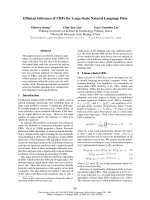
Figure 1-1: Diagram of the International Thermonuclear Fusion Experimental Reactor (ITER).
power the world for another 20,000 years, but have limited public acceptance, because
of concerns about proliferation and high-level waste.
Nuclear fusion reactors have the potential to provide energy for orders of magnitude longer than any of these options. Although the first electricity producing
fusion reactor is still decades away, extremely productive experimental reactors are
providing the needed information to design the first fusion based power plant. The International Thermonuclear Experimental Reactor (ITER) is a joint project to build
the first power plant size fusion reactor, capable of generating 500 MW of fusion
power, as seen in Figure 1-1 [9].
The massive size of ITER is seen by the inclusion of a person in the bottom
left of Figure 1-1. Engineering a system of this size is difficult, not to mention the
24