Machine design basics B (cở sở thiết kế chi tiết máy)
Bạn đang xem bản rút gọn của tài liệu. Xem và tải ngay bản đầy đủ của tài liệu tại đây (1.63 MB, 40 trang )
Kon-41.2010 Machine design basics B (4 cr)
Machine elements
Strength calculation................................................................................................................ 1
Symbols and units.......................................................................................................................................... 1
Stresses .......................................................................................................................................................... 1
Failure theories .............................................................................................................................................. 2
Static load ...................................................................................................................................................... 3
Fatigue loads.................................................................................................................................................. 3
Stress concentration factors ........................................................................................................................... 4
Reversed stress (mean stress zero) ................................................................................................................ 5
Smith diagrams (non-alloy structural steels) ................................................................................................. 7
Engineering materials............................................................................................................. 8
Steels ............................................................................................................................................................. 8
Cast irons..................................................................................................................................................... 10
Aluminium................................................................................................................................................... 11
Copper alloys............................................................................................................................................... 11
Physical properties of steels and cast irons.................................................................................................. 12
Physical properties of materials................................................................................................................... 13
Bolted joint........................................................................................................................... 14
1 Stresses of a bolt during tightening .......................................................................................................... 14
2 Torque required to tighten the bolt ........................................................................................................... 15
Welded connections ............................................................................................................. 17
Stresses in fillet weld................................................................................................................................... 17
Simple calculation method .......................................................................................................................... 17
Parallel keys ......................................................................................................................... 18
Interference fits .................................................................................................................... 19
Spring design........................................................................................................................ 20
1 Helical extension and compression springs .............................................................................................. 20
2 Belleville springs ...................................................................................................................................... 21
3 Rubber springs.......................................................................................................................................... 22
Gears..................................................................................................................................... 23
Helical gears (external gears) ...................................................................................................................... 24
Forces on gear teeth..................................................................................................................................... 25
Mechanical power transmission .................................................................................................................. 26
Narrow V-belt drives (SFS 3527) ........................................................................................ 27
Datum lengths of narrow V-belts and datum diameters of pulleys............................................................. 28
Rolling bearings ................................................................................................................... 30
Equivalent dynamic bearing load (constant) ............................................................................................... 32
Lubrication and lubricant classification ............................................................................... 33
1 Lubrication mechanisms........................................................................................................................... 33
2 Oil classification....................................................................................................................................... 34
Design of pressure vessels.................................................................................................... 36
1 Pressure equipment directive.................................................................................................................... 36
2 Nominal design stress............................................................................................................................... 36
3 Cylindrical and spherical shells ................................................................................................................ 36
4 Dished ends .............................................................................................................................................. 38
1
Machine Elements/SK
Strength calculation
Symbols and units
Quantity
Acceleration
Force
Gravity
Moment of inertia
Torque
Mass
Rotation speed
Power
Work
Symbol
a
E
F
G
J
Mv, T
m
n
P
W
SI-unit
m/s2
N/mm2, MPa
N
N
kgm2
Nm
kg
r/min, r/s
W
Nm, J
Radius
Diameter
Length
r
d
l
m, mm
m, mm
m, mm
Modulus of elasticity
Quantity
Area
Pressure
Density
Stress (tensile, com-
Symbol
A
p
ρ
σ
SI-unit
m2
Pa, N/m2, bar
kg/m3
N/mm2, MPa
τ
∆l (δ)
ε
t
v
ω
α
η
µ
N/mm2, MPa
m, mm
s
m/s
rad/s
rad/s2
-
pression, bending)
Shear stress
Extension
Strain
Time
Velocity
Angular velocity
Angular acceleration
Efficiency
Friction coefficient
Stresses
F
A
Tensile stress
σ=
♦ Hooke’s law
σ = Eε
= E∆l / l
Shear stress
τ=
F
A
Surface pressure
p=
F
A
F
projected
area
D
Bending stress
σ=
M
W
Torsion stress
τ=
Mv
Wv
B
2
Machine Elements/SK
W
Wz = Wy =
≈ 0, 1d 3
Wv
Cross-section area A
πd 3
≈ 0, 2d 3
16
πd 2
A=
4
πd 3
32
π( D 4 − d 4 )
Wz = Wy =
32 D
π( D4 − d 4 )
16 D
( D4 − d 4 )
≈ 0, 2
D
A=
π( D2 − d 2 )
4
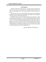
σ
Rm
ReH
ReL
σ = F/A
tensile stress
cross-section area
δ length change (extension)
= δ/L strain
A
Modulus of elasticity E = tan β
ε
β
ε
ReH
ReL
Rm
upper yield strength
lower yield strength
tensile strength.
Fig. 1. Stress-strain –diagram (low carbon steel).
Failure theories
Distortion energy theory, effective stress
σ vert = σ 2 + 3 τ 2
(1)
Maximum shear stress theory, effective stress
σ vert = σ 2 + 4τ 2
(2)
3
Machine Elements/SK
Static load
A. Ductile (tough) material
Effective stress
σ vert ≤ σ sall =
ReL
n
(3)
where ReL is a yield strength and n safety factor. Normally n = 1,2...2.
B. Brittle material
Effective stress
σ vert ≤
Rm
n
(4)
where Rm is a tensile strength and safety factor n = 2...4.
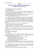
Fatigue loads
a) Fully reversed
c) Fluctuating
Fig. 2.
Fatigue loads.
b) Repeated
4
Machine Elements/SK
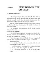
Stress concentration factors
Bending
Torsion
Fig. 3. Stress concentration factor for a shaft shoulder.
The maximum stress (bending)
σmax = Kft σnim
(5)
σnim is a nominal stress, Kft is a stress concentration factor
Kft = 1 + q(Ktt - 1)
(6)
where q is a notch sensitivity of the material (steel S355: q ≈ 0,9) and Ktt geometric stress
concentration factor (fig. 3).
5
Machine Elements/SK
1
k1
Surface roughness
Ra = 0,3
0,9
0,6
0,8
1,6
3,2
0,8
0,7
6,3
0,6
0,5
Rolled, forged
or casted
25
300 400 500 600 700 800 900 1000 1100 1200 1300 1400
Tensile strength Rm (N/mm2)
Fig. 4. Surface quality factor k1.
k2
1
0,9
0,8
0,7
0,6
10
20
30
40
50
60
70
80
90 100 110 120
d
(mm)
Fig. 5. Size factor k2.
Reversed stress (mean stress zero)
Bending or tensile-compression load (mean stress σm = 0)
n=
k1k2σ w
K ftσ nim
(7)
Torsion load (mean stress τm = 0)
n=
k1k2τ w
K fvτ nim
(8)
In other cases the safety factor is calculated using Smith diagram.
Table 1. Physical properties of structural steels.
Steel
Tensile
(N/mm2)
Bending
(N/mm2)
Torsion
(N/mm2)
Re
σw
Rte
σtw
τvs
τvw
S235 (Fe 37)
235
175
335
195
170
135
E295 (Fe 50)
295
230
410
250
205
175
S355 (Fe 52)
355
245
490
265
240
215
6
Machine Elements/SK
Notched specimen
Shape
Stress concentration factor Kf
Bending Kft
Torsion Kfv
Groove
1,5...2
1,3...1,8
Retaining ring
groove
2,5...3,5
2,5...3,5
Shoulder fillet
≈ 1,5
r/d = 0,1
and d/D = 0,7
≈ 1,25
r/d = 0,1
and d/D = 0,7
Transverse hole
1,4...1,8
d/D = 0,14
1,4...1,8
d/D = 0,14
End-milled
keyway *
2,6...3
≈ 2,3
Sled-runner
keyway *
2...2,5
2...2,5
Shaft-hub
connection:
interference fit
1,7...1,9
1,3...1,4
Shaft-hub
connection: key
2...2,4
1,5...1,6
* Stress concentration factor depends on corner radius and material.
Fig. 6. Preliminary design values for stress concentration factors.
7
Machine Elements/SK
Smith diagrams (non-alloy structural steels)
Raaka-ainekäsikirja 1. Muokatut teräkset. 3. uudistettu painos. Metalliteollisuuden Kustannus
Oy 2001. 361 s. ISBN 951-817-751-1.
N/mm2
400
ReH =
355
S355
E295
300
245
230
295
S235
235
200
175
σw
100
0
100
200
300
400
σm (N/mm2)
-σw -100
-175
-200
-245
-230
Tensile - compression
-300
a)
N/mm2
Rte=
490
S355
500
E295
400
410
S235
335
300
N/mm2
300
S355
265
200
σtw
215
250
200
175
135
195
τvw
100
0
200
300
400
500
σm (N/mm2)
-σtw -100
-τvw
170
100
0
100
E295
S235
τvs =
240
205
100
200
τm
300
(N/mm2)
-100
-135
-195
-175
-200
-200
-250
-265
-215
Torsion
Bending
-300
b)
Fig. 7.
c)
8
Machine Elements/SK
Engineering materials
Steels
According to SFS-EN 10027-1
1
Steels designated according to their application and mechanical or physical properties
Principal symbols:
• S
structural steel
• P
steels for pressure purposes
• L
steels for pipelines
• E
engineering steel
̇ followed by a number being the specified minimum yield strength (N/mm2), e.g. S235, E295
̇ for steel casting the name shall be preceded by the letter G
̇ additional symbols for impact strength etc, e.g. S355J2
Table 1. Structural steels.
SFS-EN
10025
v. 2004
S235JR
S235J0
S235J2
S275JR
S275J0
S275J2
S355JR
S355J0
S355J2
S355K2
S185
E295 3)
E335 3)
E360 3)
Yield
strength 1)
ReH (N/mm2)
235
235
235
275
275
275
355
355
355
355
185
295
335
360
1) Nominal thickness ≤ 16 mm.
Tensile
strength 2)
Impact
strength
SFS-EN
10025
SFS 200
Rm (N/mm2)
360...510
360...510
360...510
430...580
430...580
430...580
510...680
510...680
510...680
510...680
310...540
490...660
590...770
690...900
KV (J) / t (°C)
27 / 20
27 / 0
27 / -20
27 / 20
27 / 0
27 / -20
27 / 20
27 / 0
27 / -20
40 / -20
-/-/-
v. 1991
Fe 360 B FN
Fe 360 C
Fe 360 D2
Fe 430 B
Fe 430 C
Fe 430 D2
Fe 510 B
Fe 510 C
Fe 510 D2
Fe 510 DD2
Fe 310-0
Fe 490-2
Fe 590-2
Fe 690-2
v. 1986
Fe 37 B
2) Nominal thickness < 3 mm.
Classification by impact strength
(SFS-EN 10027-1)
Test temperature Impact strength (J)
°C
20
0
-20
-30
-40
-50
-60
27 J
JR
JO
J2
J3
J4
J5
J6
40 J
KR
KO
K2
K3
K4
K5
K6
60 J
LR
LO
L2
L3
L4
L5
L6
3) Engineering steels.
Fe 44 B
Fe 52 C
Fe 33
Fe 50
Fe 60
Fe 70
9
Machine Elements/SK
2
Steels designated according to chemical composition
(Examples in tables 2…4)
Non-alloy steels
• letter C and the carbon content % multiplied by 100
Non-alloy steels (with Mn ≥ 1 %), non-alloy free-cutting steels and alloy steels (except
high speed steels) where the content, by weight, of every alloying element is < 5 %
• carbon content % multiplied by 100
• chemical symbols indicating the alloy elements (in decreasing order)
• numbers indicating the values of contents of alloy elements
Alloy steels (except high speed steels)
• letter X
• carbon content % multiplied by 100
• chemical symbols indicating the alloy elements (in decreasing order)
• numbers indicating the values of contents of alloy elements
Table 2. Quenched and tempered steels (SFS-EN 10083).
Material
Re (N/mm2)
Rm (N/mm2)
370
450
650
800
630...780
700...850
900...1100
1000...1200
2 C 45
25 CrMo 4
42 CrMo 4
34 CrNiMo 6
(40 mm < d < 100 mm)
̇
̇
heat treatment including hardening and annealing in relative high temperature (500…700 °C)
shafts, couplings, gears, bolts and nuts.
Table 3. Case hardening steels.
̇
̇
̇
SFS-EN 10084
Re (N/mm2)
Rm (N/mm2)
Hardness HB
20NiCrMo2-2
16MnCr5
20NiCrMo5
18CrNiMo7-6
490
590
690
780
740...1030
790...1080
1030...1370
1080...1330
265
285
345
370
higher carbon content in thin surface layer
high wear resistance and fatigue strength and bending strength
gears and shafts.
Table 4. Stainless steels.
̇
̇
̇
SFS-EN
10088-2
Yield strength
Rp0,2 (N/mm2)
Tensile strength
Rm (N/mm2)
Modulus of elasticity
E (N/mm2)
X2CrNi19-11
X2CrNi18-9
X5CrNi18-10
X2CrNiMo17-12-2
X3CrNiMo17-13-3
200
200
210
220
220
500...650
500...650
520...720
520...670
530...730
200 000
200 000
200 000
200 000
200 000
corrosion resistant
ductile at low temperatures
pipes, vessels, valves, machinery in process industry, containers and tanks.
10
Machine Elements/SK
Cast irons
Table 5. Grey cast irons.
SFS-EN 1561
EN-GJL-150
EN-GJL-200
EN-GJL-250
EN-GJL-300
EN-GJL-350
̇
̇
Rm (N/mm2)
Rp0,1 (N/mm2)
Elongation (%)
150…250
200…300
250…350
300…400
350…450
98…165
130…195
165…228
195…260
228…285
0,8…0,3
0,8…0,3
0,8…0,3
0,8…0,3
0,8…0,3
low cost, good for casting and easy machining, absorption of vibration
machine beds, valves, pipes, cylinders and lining, brake drums and disks.
Table 6. Spheroidal graphite cast irons (ductile irons).
̇
̇
SFS-EN 1563
Rm (N/mm2)
Rp0,2 (N/mm2)
Elongation (%)
EN-GJS-350-22
EN-GJS-400-18
EN-GJS-400-15
EN-GJS-450-10
EN-GJS-500-7
EN-GJS-600-3
EN-GJS-700-2
EN-GJS-800-2
EN-GJS-900-2
350
400
400
450
500
600
700
800
900
220
240
250
310
320
370
420
480
600
22
18
15
10
7
3
2
2
2
high strength compared to grey cast iron, heat treating possible
gears, bodies and frames, power transmission, combustion engine and paper machine
components.
Table 7. Austempered Ductile Irons (ADI).
Yield strength Tensile strength Elongation Hardness
EN 1564 (N/mm2)
(N/mm2)
(%)
(HB)
800-8
1000-5
1200-2
1400-1
500
700
850
1100
800
1000
1200
1400
8
5
2
1
260...320
300...360
340...440
380...480
11
Machine Elements/SK
Aluminium
̇
̇
̇
̇
̇
low weight
corrosion resistant
good heat and electricity conductivity
special alloys with high strength
aluminium profiles
•
•
̇
economical manufacturing
material extruded trough profile tool
aluminium casting
•
•
•
low weight
ductile
easy to machine
Table 8. Aluminium profile alloys.
Alloy
Yield strength Tensile strength Elongation Hardness
(N/mm2)
(N/mm2)
A5 (%)
(HB)
Al 99,5
AlMg2,5
E-AlMgSi
AlSi1Mg
AlSi1MgPb
AlZn5Mg1
20
80
180
260
180
280
23
14
10
8
8
10
70
180
220
300
280
330
18...25
35...45
65...75
95...115
85...95
115...125
Modulus of elasticity E ≈ 70 000 N/mm2
Copper alloys
̇
journal bearings are most important applications
Table 9. Common copper alloys.
Alloy
CuZn39Pb3
Lead brass
CuZn35Mn2AlFe
Special brass
CuSn6
Tin bronze
GK-CuZn40Pb
Lead brass
GS-CuSn12
Tin bronze
GS-CuPb10Sn10
Lead tin bronze
GS-CuAl10Fe3
Aluminium bronze
Products
Bolts, nuts, valves, connectors
Shafts, piston rods,
gears, bolts, nuts, valves
Springs, valve and
pump components
Components of devices,
locks, decorative parts
Gears and worm wheels,
sliding surfaces, journal
bearings
Heavily loaded journal
bearings (edge contact)
Crane wheels, bushings,
gears, journal bearings
Yield
strength
(N/mm2)
Tensile
strength
(N/mm2)
Elongation Hardness
A5 (%)
(HB)
250...
430
270...
440
390...
490
430...
520
470...
590
470...
550
15...30
120
280
15
70
160
280
12
95
80
180
7
65
180
500
13
115
15...30
15...40
115...
155
135...
170
-
12
Machine Elements/SK
Physical properties of steels and cast irons
Material
Structural steels
Quenched and tempered steels
Case hardening steels
Stainless steels:
X4CrNi 18 9
X4CrNiMo 17 12 3
Grey cast irons
GJL-150 (GRS 150)
GJL-200 (GRS 200)
GJL-250 (GRS 250)
GJL-300 (GRS 300)
GJL-350 (GRS 350)
Spheroidal graphite cast irons
GJS-350
GJS-400 (GRP 400)
GJS-450
GJS-500 (GRP 500)
GJS-600 (GRP 600)
GJS-700 (GRP 700)
GJS-800 (GRP 800)
GJS-900
ADI - Austempered ductile
cast irons
GJS-800-8
GJS-1000-5
GJS-1200-2
GJS-1400-1
1)
t = 100 °C
2)
t = 300 °C
Poisson's
ratio
Thermal
conductivity
52…63
42…59
42…59
Specific heat
capacity c
(kJ/(kg K))
0,50
0,50
0,50
0,44
0,44
ν
Density ρ
(kg/m3)
206
206
206
0,3
0,3
0,3
7850
7850
7850
Linear expansion coefficient
α (1/K)
12⋅10-6
12⋅10-6
12⋅10-6
200
200
0,3
0,3
7900
8000
17⋅10-6
16,5⋅10-6
15
13,5
78…103
88…113
103…118
108…137
123…143
0,26
0,26
0,26
0,26
0,26
7100
7150
7200
7250
7300
11,7⋅10-6
11,7⋅10-6
11,7⋅10-6
11,7⋅10-6
11,7⋅10-6
52,5
50,0
48,5
47,5
45,5
169
169
169
169
174
176
176
176
0,275
0,275
0,275
0,275
0,275
0,275
0,275
0,275
7100
7100
7100
7100
7200
7200
7200
7200
12,5⋅10-6
12,5⋅10-6
12,5⋅10-6
12,5⋅10-6
12,5⋅10-6
12,5⋅10-6
12,5⋅10-6
12,5⋅10-6
36,2
36,2
36,2
35,2
32,5
31,1
31,1
31,1
170
168
167
165
0,27
0,27
0,27
0,27
7100
7100
7100
7100
14,6⋅10-6
14,3⋅10-6
14,0⋅10-6
13,8⋅10-6
22,1
21,8
21,5
21,2
E
(GN/m2)
λ (W/(m K))
1)
0,46
0,46
0,46
0,46
0,46
2)
0,515
0,515
0,515
0,515
0,515
0,515
0,515
0,515
References
Raaka-ainekäsikirja 1. Muokatut teräkset. 3. uudistettu painos. Metalliteollisuuden Kustannus Oy
2001. 361 s. ISBN 951-817-751-1.
Raaka-ainekäsikirja 2. Valuraudat ja valuteräkset. 2. uudistettu painos. Metalliteollisuuden Kustannus
Oy 2001. 196 s. ISBN 951-817-757-0.
Raaka-ainekäsikirja 1. Muokatut teräkset. 2. tarkistettu ja uudistettu painos. Metalliteollisuuden Kustannus Oy 1993. 353 s. ISBN 951-817-564-0.
SFS-Käsikirja 138. Valurauta. Yleis- ja ainestandardit. Suomen Standardisoimisliitto 1999. 176 s.
ISBN 952-5143-38-4.
13
Machine Elements/SK
Physical properties of materials
Material
E
(GN/m2)
Poisson's
ratio
ν
Density ρ
(kg/m3)
Linear expansion coefficient α (1/K)
24⋅10-6
18⋅10-6
19⋅10-6
18⋅10-6
18⋅10-6
27⋅10-6
20⋅10-6
23⋅10-6
27⋅10-6
11,9⋅10-6
11⋅10-6
17⋅10-6
10,3⋅10-6
10…13⋅10-6
1,34⋅10-6
1,34⋅10-6
Thermal
conductivity
λ (W/(m K))
Specific heat
capacity c
(kJ/(kg K))
0,900
0,380
0,390
0,380
0,380
1,000
0,150
0,210
0,400
Aluminium alloy
146 (cast) 4)
70
0,33
2700
Copper
170
124
0,33
8900
Brass
120 4)
100
0,33
8600
Aluminium bronze
50 4)
117
0,33
7500
Lead bronze
47
97
0,33
8900
Magnesium alloy
110
41
0,33
1800
Babbitt (lead)
24
29
10100
Babbitt (tin)
56
52
7400
Zinc alloy
110
50
0,27
6700
Nickel alloy
207
0,30
Steel
200
0,30
7800
35
0,450
Stainless steel
193
0,30
7800
15
0,450
Titanium
110
0,33
Grey cast iron1)
76...176
0,2...0,3
7100...7300
31...53
0,46...0,54
800
0,510
Diamond (natural)2)
965
0,20
3515
2000
0,510
Synthetic diamond2)
1000
0,20
3515
Aluminium oxide
7⋅10-6
30
0,752
(polycrystal)3)
345
0,23
3900
3)
4⋅10-6
50
0,670
Silicon carbide
400
0,15
3200
1,26⋅10-6
30,7
0,710
Silicon nitride3)
310
0,27
3200
9⋅10-6
55
0,543
Titanium carbide3)
393
0,21
6000
5⋅10-6
102
0,205
Tungsten carbide3)
655
0,24
15100
Graphite3)
14
0,30
1900
3⋅10-6
178
0,710
Nylon3)
2,6...3,3
0,32...0,36
1140
81⋅10-6
0,25
1,670
Reinforced nylon3)
9,6...14
0,32...0,36
1420
(25…38)⋅10-6
0,22…0,48
Polyimide3)
3,2...5,2
0,41
1430
(45…50)⋅10-6
0,36…0,98
1,13…1,30
Teflon3)
0,26...0,45
0,45
2200
(135…151)⋅10-6
0,24
1,050
Silicon oxide (glass)
68
0,16
2200
0,6⋅10-6
1,25
0,800
1) Values are representative. Exact values vary with composition and processing.
2) Materials are anisotropic. Values vary with crystallographic orientation.
3) Typical properties of bearing quality materials. Ceramics are hot pressed or equivalent sintered. These properties are representative and depend on detailed composition and processing.
4) t = 100 °C
References
Hamrock B. J. Fundamentals of Fluid Film Lubrication. McGraw-Hill, New York 1994. 690 s. ISBN
0-07-025956-9.
Wear Control Handbook (Ed. Peterson & Winer). New York 1980. 1358 p.
14
Machine Elements/SK
Bolted joint
1 Stresses of a bolt during tightening
A flange joint is a typical bolted joint (fig. 1-1).
Fig. 1-1. Flange joint.
When the bolt is tightened, a tensile stress and torsional stress is developed in the bolt. For
ISO metric threads (thread angle 60°) the friction torque in threads is /1/
⎛
P ⎞
⎟
M G = 12 d 2 FM ⎜⎜1,155µ G +
πd 2 ⎟⎠
⎝
where FM
d2
µG
P
(1-1)
is the preload (from tightening)
the pitch diameter (table 1-1)
the friction coefficient in threads
the pitch.
The torsional stress in a round section (diameter dS) is
τ=
M G 8d 2 FM
=
Wv
πdS3
⎛
P ⎞
⎟⎟
⎜⎜1,155µG +
π
d
2⎠
⎝
The equation for the diameter dS of the thread is /1, 2/
d + d3
dS = 2
2
(1-2)
(1-3)
where d3 is the root diameter of the thread. If the bolt has a reduced diameter (< dS), use the
minimum diameter dT. The tensile stress in the cross-section due to the preload force is
σS =
4 FM
πd S2
(1-4)
The effective stress is (theory of constant energy of distortion)
σ vert = σ 2S + 3 τ 2
(1-5)
15
Machine Elements/SK
The effective stress should not be more than 90 % of the yield stress (0,9Rp0,2 or 0,9ReL). The
maximum tensile stress during tightening is /1, 3/
σS =
0,9 Rp0,2
⎛ d
P ⎞
1 + 3⎜⎜ 2 2 (1,155µG +
)⎟
πd 2 ⎟⎠
⎝ dS
(1-6)
2
The friction coefficient in threads depends on the material, surface treatment and lubrication.
(table 1-2). For bolts M6...M16 σS ≈ 0,7ReL, when the friction coefficient in threads is µG =
0,15. The maximum axial force (in assembled state) is
FSP = σS AS
(1-7)
where AS is the tensile stress area of the bolt (table 1-1). Property classes of bolts are in the
table 1-3 (SFS-ISO 898-1).
Table 1-1. Selected dimensions of ISO metric threads.
Thread
Nominal
diameter
d/mm
Pitch
P/mm
M6
M8
M 10
M 12
M 16
M 20
6
8
10
12
16
20
1,0
1,25
1,5
1,75
2,0
2,5
Pitch
diameter
d2/mm
Root
diameter
d3/mm
5,350
7,188
9,026
10,863
14,701
18,376
4,773
6,466
8,160
9,853
13,546
16,933
Tensile
stress area
AS/mm2
Width across
flats s/mm
SFS-ISO 272
20,1
36,6
58,0
84,3
157
245
10
13
16
18
24
30
Table 1-2. Friction coefficient µG in threads /4/.
Surface treatment
Dry
Oiled
MoS2
Untreated
Phosphated
Phosphated black
Zinc electroplated
Cadmium electropl.
0,20...0,35
0,28...0,40
0,26...0,37
0,14...0,20
0,10...0,19
0,16...0,23
0,16...0,33
0,24...0,27
0,14...0,19
0,10...0,17
0,13...0,19
0,13...0,19
0,14...0,21
0,10...0,17
0,13...0,19
Table 1-3. Property classes (strength grades) of bolts.
Property class
N/mm2
Rm /
ReL or Rp0,2 / N/mm2
(nominal)
(nominal)
5.6
6.8
8.8
10.9
12.9
500
300
600
480
800
640
1000
900
1200
1080
Rm tensile strength, ReL or Rp0,2 yield strength.
2 Torque required to tighten the bolt
The total torque required to tighten the bolt is a sum of the friction torque in threads and
torque between the head or nut and the surface (fig. 2-1). The friction torque MK between the
nut and the surface is
M K = 12 µ K Dkm FM
(2-1)
16
Machine Elements/SK
where µK is the friction coefficient between the nut (or head) and the surface
Dkm = (dK+DK)/2 the mean diameter (location of friction force)
dK the outside diameter of the nut (or head) ≈ width across flats s (wrench opening)
DK the diameter of the hole.
The friction coefficient between the nut (or head) and the surface is µK ≈ 0,08...0,22 depending on the material, surface treatment and lubrication. The friction coefficient of stainless
steels (between the nut (or head) and the surface or in threads) can be even 0,5.
The total torque required to tighten the bolt is
MA = MG + MK =
Fig. 2-1.
1
P⎞
⎛
FM ⎜1,155µG d 2 + µ K Dkm + ⎟
π⎠
2
⎝
(2-2)
Bolt tightening using wrench.
The preload FM depends on friction coefficients and torque. With hand tools only bolts M10
(10.9) and M12 (8.8) are tightened properly (preload of small bolts is usually too high and
preload of big bolts is too small) /1/.
References
1.
Verho A. Ruuviliitokset ja liikeruuvit. Julkaisussa: Airila M. et al. Koneenosien suunnittelu, 2. painos.
Porvoo: WSOY 1997. S. 161...243. ISBN 951-0-20172-3.
2.
Decker K-H. Maschinenelemente. Gestaltung und Berechnung. 12. Auflage. München: Carl Hanser
Verlag 1995. 677 s. ISBN 3-446-17966-6.
3.
VDI Richtlinie 2230 Blatt 1. Systematische Berechnung hochbeanspruchter Schraubenverbindungen.
Düsseldorf: VDI-Verlag 1986. (Systematic calculation of high duty bolted joints)
4.
Haberhauer H. & Bodenstein F. Maschinenelemente. Gestaltung, Berechnung, Anwendung. 10. Auflage.
Berlin: Springer-Verlag 1996. 626 s. ISBN 3-540-60619-X.
17
Machine Elements/SK
Welded connections
Stresses in fillet weld
The stresses of the fillet weld are calculated for the minimum cross section A = al (a is the
throat thickness (height of the cross section area) and l is the length of the weld). The minimum cross section area is located at 45° to the legs. The stresses of the area are divided into
three components (fig. 1).
a
τ⊥
σ⊥
Stresses on the throat section of a fillet weld.
Fig. 1.
Simple calculation method
In the simple calculation method the equation for the stress of the weld σw is regardless of the
direction of the load
σw =
F
al
(1)
The resistance of the weld is sufficient if (SFS 2373)
σ w ≤ σ wsall
(SFS 2373: σ sall =
σ
ReL
, σ wsall = sall )
n
β 3
(2)
The calculation method is valid when 3 mm ≤ a ≤ 15 mm (SFS 2373). The length of the weld
has also limitations.
Mechanical properties of structural steels are in the table 1.
Table 1.
Mechanical properties of structural steels.
Thickness t / mm ReL / N/mm2 σsall / N/mm2 σwsall / N/mm2 Factor β
120
147
S 235 (Fe 37)
...16
220
0,7
115
140
210
17...40
110
133
200
41...
S 355 (Fe 52)
...16
340
227
145
17...30
330
220
140
0,9
31...
320
213
135
Steel
18
Machine Elements/SK
Parallel keys
The torque that can be transmitted (the bearing action between the side of the key and the hub
material) (fig. 1)
Mvn = pn l t2 (d + t2)/2
where pn
l
t2
d
(1)
is the compressive stress of the hub
is the length of the key
the depth of the keyway in the hub
the diameter of the shaft.
The torque that can be transmitted (the bearing action between the side of the key and the
shaft material)
Mva = pa l t1 (d - t1)/2
(2)
where pa is the compressive stress of the hub and t1 the depth of the keyway in the shaft.
pn
The compressive stress po is:
◊
◊
◊
150 N/mm2
90 N/mm2
110 N/mm2.
the steel
grey cast iron
spheroidal graphite cast iron
pa
Mv
The load factor is in the table 2.
Fig. 1. Parallel key (SFS 2636).
Table 1. Dimensions of keys (SFS 2636). Key length is in the standard.
Width b (tol. h9)
2
3
4
5
6
8
10 12 14 16 18
20
22
25
28
32
36
40
45
50
Height h
2
3
4
5
6
7
8
10 11
12
14
14
16
18
20
22
25
28
Diameter of shaft d >
6
8
10 12 17 22 30 38 44 50 58
65
75
85
95 110 130 150 170 200
≤
8
10 12 17 22 30 38 44 50 58 65
75
85
95 110 130 150 170 200 230
7,5
9
9
Depth of keyway (shaft) t1 1,2 1,8 2,5
Depth (hub)
t2
1
3
3,5
4
5
8
5
9
5,5
6
7
10
11
12
13
15
1,4 1,8 2,3 2,8 3,3 3,3 3,3 3,8 4,3 4,4 4,9 5,4 5,4 6,4 7,4
8,4
9,4 10,4 11,4
Table 2. The design compressive stress psall = Cpo.
One-way load,
static
0,8po
One-way load,
light shocks
0,7po
One-way load,
heavy shocks
0,6po
Reverse load,
light shocks
0,45po
Reverse load,
heavy shocks
0,25po
17
19
Machine Elements/SK
Interference fits
A press fit is obtained by machining the hole in the hub to a slightly smaller diameter than
that of the shaft. Only relative small parts can be press-fitted. For large parts a shrink fit can
be made by heating the hub to expand its inside diameter.
a)
da
b)
Di
di
ua
Da
c)
σvn
σt
σr
σtn
p
DF
p
σra
un
σrn
σva
σta
compression
Fig. 1. An interference fit and stresses in interference fits.
Table 1. Interference fits (sizes mm).
Nominal
sizes
>
H7
u6
+0,024
+0,018
+0,031
+0,023
+0,037
+0,028
14 +0,018 +0,039
+0,044
+0,033
3
6
6
10
+0,010
0
+0,012
0
+0,015
0
0
+0,028
14
18
18
24 +0,021 +0,048
24
30
30
40 +0,025 +0,059
40
50
50
65 +0,030 +0,053
65
80
0
0
+0,035
+0,043
+0,072
0
80
t6
+0,020
+0,014
+0,027
+0,019
+0,032
+0,023
3
10
s6
v6
Devia- Devia- Devia- Devia- Devia≤ tions
tions
tions
tions
tions
100 +0,035
0
100
120
120
140
140
160
160
180
180
200
+0,040
0
+0,078
+0,059
+0,093
+0,071
+0,101
+0,079
+0,117
+0,092
+0,125
+0,100
+0,133
+0,108
+0,151
+0,122
+0,054
+0,041
+0,064
+0,048
+0,070
+0,054
+0,085
+0,066
+0,094
+0,075
+0,113
+0,091
+0,126
+0,104
+0,147
+0,122
+0,159
+0,134
+0,171
+0,146
+0,195
+0,166
+0,054
+0,041
+0,061
+0,048
+0,076
+0,060
+0,086
+0,070
+0,106
+0,087
+0,121
+0,102
+0,146
+0,124
+0,166
+0,144
+0,195
+0,170
+0,215
+0,190
+0,235
+0,210
+0,265
+0,236
+0,050
+0,039
+0,060
+0,047
+0,068
+0,055
+0,084
+0,068
+0,097
+0,081
+0,121
+0,102
+0,139
+0,120
+0,168
+0,146
+0,194
+0,172
+0,227
+0,202
+0,253
+0,228
+0,277
+0,252
+0,313
+0,284
20
Machine Elements/SK
Spring design
1 Helical extension and compression springs
Common forms of helical springs are in fig. 1. For springs with end treatments the total number of coils nt is bigger than the number of active coils n. Other forms are possible such as
conical helical compression springs. If the place for a spring is small it is possible to put several helical springs within each other.
Helical compression springs (a) and extension spring (b).
Fig. 1.
The force of a helical spring is
F=
where G
d
D
n
f
Gd 4
8D3n
f
(1)
is the shear modulus of elasticity
the wire diameter
the mean coil diameter
the number of active coils
the deflection.
The spring rate (spring constant) for a helical spring is (F = kf)
k=
Gd 4
8D3n
The nominal shear stress of the wire’s cross-section is
8 DF
Gd
τ=
=
f
3
πd
πnD2
(2)
(3)
The maximum shear stress is
τtod = kτ
(4)
21
Machine Elements/SK
where k is the stress concentration factor. The stress concentration factor kw for the dynamic
load (the Wahl factor) is as a function of the spring index C = D/d in fig. 2.
The stress concentration factor for the static load is
ks = 1 +
1
2C
(5)
kw =
4 C − 1 0,615
+
4C − 4
C
Stress concentration factor or Wahl factor.
Fig. 2.
2 Belleville springs
φ De
Groups 1 and 2
t
l0
h0
φDi
OM
t' III
Fig. 3.
De/t
18
28
40
h0/t
0,4
0,75
1,3
φ De
Group 3
l0 IV
Class
A
B
C
I
h0
II
φDi
Forms of Belleville springs, the top and bottom of springs in group 3 are chamfered. Belleville springs have three dimension classes A, B and C (DIN 2093).
The force-deflection relationship is nonlinear. The allowed deflection f ≤ 0,75h0.
22
Machine Elements/SK
Fig. 4. Deflection of Belleville spring.
3 Rubber springs
The modulus of elasticity E and G (in shear) for rubber depends on the durometer hardness
number (e.g. IRHD). Dynamically loaded rubber springs have higher stiffness than statically
loaded. A cylindrical rubber spring is frequently used as a compression spring (fig. 5).
Fig. 5. Cylindrical rubber spring with compression loading.
Fig. 6. Simple rubber shear spring.
Fig. 7. Cylindrical rubber spring
(torsion loading).
23
Machine Elements/SK
Gears
Gears are used to transmit torque and angular velocity in many applications. There is a wide
variety of gear types to choose from.
Spur gears
Helical gears
Spur gears, internal set
Bevel gears
Worm and worm gear
Rack and pinion
Crossed helical gears
24
Machine Elements/SK
Helical gears (external gears)
Normal module mn, pressure angle αn = 20°, helix angle β, number of teeth z, facewidth b and
addendum modification coefficient x (SFS 3390).
Equation
mn
cos β
Tranverse module
mt =
Transverse pressure angle
α t = arctan
Tranverse pitch
pt = mtπ
(3)
Tranverse base pitch
pbt = pt cosα t
(4)
Reference diameter
d = mt z
(5)
Base diameter
d b = d cos α t
(6)
Addendum of gear tooth
ha = mn (1 + x ) − ∆ha
(7)
Correction of addendum
⎞
⎛ z +z
∆ha = mn ⎜⎜ 1 2 + x1 + x2 ⎟⎟ − aw
β
2
cos
⎝
⎠
If ∆ha < 0 , then ∆ha = 0
Dedendum
hf = mn (1,25 − x )
(9)
Tip diameter (outside diameter)
d a = d + 2ha
(10)
Root diameter
d f = d − 2hf
(11)
Base centre distance
(no profile- shift)
a=
Centre distance
Working pressure angle
(1)
tan α n
cos β
mt ( z1 + z2 )
2
cos α t
aw = a
cos α wt
cos α wt =
a cos α t
aw
invα wt = invα t +
Involute function
(2)
(12)
(13)
(14)
2( x1 + x2 ) tan α n
z1 + z2
invα = tan α − α
Transverse contact ratio
(8)
⎞
⎛ d2 − d2
d a22 − d b22
⎟
⎜
b1
⋅ ⎜ a1
+
− a w sin α wt ⎟
2
2
⎜
⎟
⎝
⎠
(15)
εα =
1
p bt
Overlap ratio
εβ =
b tan β
pt
(17)
Total contact ratio
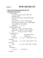
ε γ = εα + ε β
(18)
Fig. 1. Involute gear (a), bottom clearance c and backlash j (b).
(16)