Hướng dẫn thiết kế bê tông cốt thép theo tiêu chuẩn Anh (BSHK)
Bạn đang xem bản rút gọn của tài liệu. Xem và tải ngay bản đầy đủ của tài liệu tại đây (2.73 MB, 346 trang )
Manual for Design and
Detailings of
Reinforced Concrete to
Code of Practice for
Structural Use of Concrete
2004
Housing Department
May 2008
(Version 2.3)
Acknowledgement
We would like to express our greatest gratitude to Professor A.K.H. Kwan
of The University of Hong Kong who has kindly and generously provided
invaluable advice and information during the course of our drafting of
the Manual. His advice is most important for the accuracy and
completeness of contents in the Manual.
Contents
Page
1.0
Introduction
1
2.0
Some highlighted aspects in Basis of Design
3
3.0
Beams
10
4.0
Slabs
49
5.0
Columns
68
6.0
Column Beam Joints
93
7.0
Walls
102
8.0
Corbels
116
9.0
Cantilever Structures
124
10.0 Transfer Structures
132
11.0 Footings
137
12.0 Pile Caps
145
13.0 General R.C. Detailings
156
14.0 Design against Robustness
163
15.0 Shrinkage and Creep
168
16.0 Summary of Aspects having significant Impacts on Current Practices 184
References
194
Appendices
Appendix A –
Appendix B –
Clause by Clause Comparison between “Code of Practice for
Structural Use of Concrete 2004” and BS8110
Assessment of Building Accelerations
Appendix C –
Derivation of Basic Design Formulae of R.C. Beam sections
against Flexure
Appendix D –
Appendix E –
Appendix F –
Underlying Theory and Design Principles for Plate Bending Element
Moment Coefficients for three side supported Slabs
Derivation of Design Formulae for Rectangular Columns to Rigorous
Stress Strain Curve of Concrete
Derivation of Design Formulae for Walls to Rigorous Stress Strain
Curve of Concrete
Estimation of support stiffnesses of vertical support to transfer
structures
Derivation of Formulae for Rigid Cap Analysis
Mathematical Simulation of Curves related to Shrinkage and Creep
Determination
Appendix G –
Appendix H –
Appendix I –
Appendix J –
Version 2.3
1.0
Introduction
1.1
Promulgation of the Revised Code
May 2008
A revised concrete code titled “Code of Practice for Structural Use of Concrete
2004” was formally promulgated by the Buildings Department of Hong Kong
in late 2004 which serves to supersede the former concrete code titled “The
Structural Use of Concrete 1987”. The revised Code, referred to as “the Code”
hereafter in this Manual will become mandatory by 15 December 2006, after
expiry of the grace period in which both the revised and old codes can be used.
1.2
Main features of the Code
As in contrast with the former code which is based on “working stress” design
concept, the drafting of the Code is largely based on the British Standard
BS8110 1997 adopting the limit state design approach. Nevertheless, the
following features of the Code in relation to design as different from BS8110
are outlined :
(a)
(b)
(c)
(d)
(e)
Provisions of concrete strength up to grade 100 are included;
Stress strain relationship of concrete is different from that of BS8110
for various concrete grades as per previous tests on local concrete;
Maximum design shear stresses of concrete ( v max ) are raised;
Provisions of r.c. detailings to enhance ductility are added, together
with the requirements of design in beam-column joints (Sections 9.9
and 6.8 respectively);
Criteria for dynamic analysis for tall building under wind loads are
added (Clause 7.3.2).
As most of our colleagues are familiar with BS8110, a comparison table
highlighting differences between BS8110 and the Code is enclosed in
Appendix A which may be helpful to designers switching from BS8110 to the
Code in the design practice.
1.3
Outline of this Manual
This Practical Design Manual intends to outline practice of detailed design and
detailings of reinforced concrete work to the Code. Detailings of individual
1
Version 2.3
May 2008
types of members are included in the respective sections for the types, though
Section 13 in the Manual includes certain aspects in detailings which are
common to all types of members. Design examples, charts are included, with
derivations of approaches and formulae as necessary. Aspects on analysis are
only discussed selectively in this Manual. In addition, as the Department has
decided to adopt Section 9.9 of the Code which is in relation to provisions for
“ductility” for columns and beams contributing in the lateral load resisting
system in accordance with Cl. 9.1 of the Code, conflicts of this section with
others in the Code are resolved with the more stringent ones highlighted as
requirements in our structural design.
As computer methods have been extensively used nowadays in analysis and
design, the contents as related to the current popular analysis and design
approaches by computer methods are also discussed. The background theory
of the plate bending structure involving twisting moments, shear stresses, and
design approach by the Wood Armer Equations which are extensively used by
computer methods are also included in the Appendices in this Manual for
design of slabs, flexible pile caps and footings.
To make distinctions between the equations quoted from the Code and the
equations derived in this Manual, the former will be prefixed by (Ceqn) and
the latter by (Eqn).
Unless otherwise stated, the general provisions and dimensioning of steel bars
are based on high yield bars with f y = 460 N/mm2.
1.4
Revision as contained in Amendment No. 1 comprising major revisions
including (i) exclusion of members not contributing to lateral load resisting
system from ductility requirements in Cl. 9.9; (ii) rectification of ε0 in the
concrete stress strain curves; (iii) raising the threshold concrete grade for
limiting neutral axis depths to 0.5d from grade 40 to grade 45 for flexural
members; (iv) reducing the x values of the simplified stress block for
concrete above grade 45 are incorporated in this Manual.
2
Version 2.3
2.0
Some highlighted aspects in Basis of Design
2.1
Ultimate and Serviceability Limit states
May 2008
The ultimate and serviceability limit states used in the Code carry the usual
meaning as in BS8110. However, the new Code has incorporated an extra
serviceability requirement in checking human comfort by limiting acceleration
due to wind load on high-rise buildings (in Clause 7.3.2). No method of
analysis has been recommended in the Code though such accelerations can be
estimated by the wind tunnel laboratory if wind tunnel tests are conducted.
Nevertheless, worked examples are enclosed in Appendix B, based on
approximation of the motion of the building as a simple harmonic motion and
empirical approach in accordance with the Australian Wind Code AS/NZS
1170.2:2002 on which the Hong Kong Wind Code has based in deriving
dynamic effects of wind loads. The relevant part of the Australian Code is
Appendix G of the Australian Code.
2.2
Design Loads
The Code has made reference to the “Code of Practice for Dead and Imposed
Loads for Buildings” for determination of characteristic gravity loads for
design. However, this Load Code has not yet been formally promulgated and
the Amendment No. 1 has deleted such reference. At the meantime, the design
loads should be therefore taken from HKB(C)R Clause 17. Nevertheless, the
designer may need to check for the updated loads by fire engine for design of
new buildings, as required by FSD.
The Code has placed emphasize on design loads for robustness which are
similar to the requirements in BS8110 Part 2. The requirements include design
of the structure against a notional horizontal load equal to 1.5% of the
characteristic dead weight at each floor level and vehicular impact loads
(Clause 2.3.1.4). The small notional horizontal load can generally be covered
by wind loads required for design. Identification of key elements and design
for ultimate loads of 34 kPa, together with examination of disproportionate
collapse in accordance with Cl. 2.2.2.3 can be exempted if the buildings are
provided with ties determined by Cl. 6.4.1. The usual reinforcement provisions
as required by the Code for other purposes can generally cover the required
ties provisions.
3
Version 2.3
May 2008
Wind loads for design should be taken from Code of Practice on Wind Effects
in Hong Kong 2004.
It should also be noted that there are differences between Table 2.1 of the
Code that of BS8110 Part 1 in some of the partial load factors γf. The
beneficial partial load factor for earth and water load is 1. However, lower
values should be used if the earth and water loads are known to be
over-estimated.
Materials – Concrete
Table 3.2 has tabulated a set of Young’s Moduli of concrete up to grade 100.
The values are generally smaller than that in BS8110 by more than 10% and
also slightly different from the former 1987 Code. The stress strain curve of
concrete as given in Figure 3.8 of the Code, whose initial tangent is
determined by these Young’s Moduli values is therefore different from Figure
2.1 of BS8110 Part 1. Furthermore, in order to achieve smooth (tangential)
connection between the parabolic portion and straight portion of the stress
strain curve, the Code, by its Amendment No. 1, has shifted the ε 0 value to
f cu
1.34( f cu / γ m )
instead of staying at 2.4 × 10 − 4
Ec
γm
which is the value in
BS8110. The stress strain curves for grade 35 by the Code and BS8110 are
plotted as an illustration in Figure 2.1.
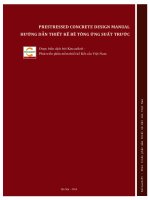
Comparison of stress strain profile between the Code and
BS8110 for Grade 35
The Code
BS8110
18
16
14
Stress (MPa)
2.3
12
10
8
6
4
2
0
0
0.2
0.4
0.6
Distance ratio from neutral axis
0.8
Figure 2.1 - Stress Strain Curves of Grade 35 by the Code and
BS8110
4
1
Version 2.3
May 2008
From Figure 2.1 it can be seen that stress strain curve by BS8110 envelops that
of the Code, indicating that design based on the Code will be slightly less
economical. Design formulae for beams and columns based on these stress
strain curves by BS8110, strictly speaking, become inapplicable. A full
derivation of design formulae and charts for beams, columns and walls are
given in Sections 3, 5 and 7, together with Appendices C, F and G of this
Manual.
Table 4.2 of the Code tabulated nominal covers to reinforcements under
different exposure conditions. However, reference should also be made to the
“Code of Practice for Fire Resisting Construction 1996”.
To cater for the “rigorous concrete stress strain relation” as indicated in Figure
2.1 for design purpose, a “simplified stress approach” by assuming a
rectangular stress block of length 0.9 times the neutral axis depth has been
widely adopted, as similar to BS8110. However, the Amendment No. 1 of the
Code has restricted the 0.9 factor to concrete grades not exceeding 45. For 45
< fcu ≤ 70 and 70 < fcu, the factors are further reduced to 0.8 and 0.72
respectively as shown in Figure 2.2
0.0035 for fcu ≤ 60
0.0035 – 0.0006(fcu – 60)1/2 for fcu > 60
0.67fcu/γm
0.9x for fcu ≤ 45;
0.8x for 45 < fcu ≤ 70;
0.72x for 70 < fcu
strain
stress
Figure 2.2 – Simplified stress block for ultimate reinforced concrete design
2.4
Ductility Requirements (for beams and columns contributing to lateral load
resisting system)
As discussed in para. 1.3, an important feature of the Code is the incorporation
of ductility requirements which directly affects r.c. detailings. By ductility we
refer to the ability of a structure to undergo “plastic deformation”, which is
5
Version 2.3
May 2008
comparatively larger than the “elastic” one prior to failure. Such ability is
desirable in structures as it gives adequate warning to the user for repair or
escape before failure. The underlying principles in r.c. detailings for ductility
requirements are highlighted as follows :
(i)
Use of closer and stronger transverse reinforcements to achieve better
concrete confinement which enhances both ductility and strength of
concrete against compression, both in columns and beams;
axial compression
confinement by transverse
re-bars enhances concrete
strength and ductility of the
concrete core within the
transverse re-bars
Figure 2.3 – enhancement of ductility by transverse reinforcements
(ii)
Stronger anchorage of transverse reinforcements in concrete by means
of hooks with bent angles ≥ 135o for ensuring better performance of
the transverse reinforcements;
(a) 180o hook
(b) 135o hook
(c) 90o hook
Anchorage of link in concrete : (a) better than (b); (b) better than (c)
Figure 2.4 – Anchorage of links in concrete by hooks
(In fact Cl. 9.9.1.2(b) of the Code has stated that links must be
adequately anchored by means of 135o or 180o hooks and anchorage by
means of 90o hooks is not permitted for beams. Cl. 9.5.2.2, Cl. 9.5.2.3
and 9.9.2.2(c) states that links for columns should have bent angle at
6
Version 2.3
(iii)
(iv)
May 2008
least 135o in anchorage. Nevertheless, for walls, links used to restrain
vertical bars in compression should have an included angle of not more
than 90o by Cl. 9.6.4 which is identical to BS8110 and not a ductility
requirement;
More stringent requirements in restraining and containing longitudinal
reinforcing bars in compression against buckling by closer and
stronger transverse reinforcements with hooks of bent angles ≥ 135o;
Longer bond and anchorage length of reinforcing bars in concrete to
ensure failure by yielding prior to bond slippage as the latter failure is
brittle;
Ensure failure by yielding here
instead of bond failure behind
bar in tension
Longer and stronger
anchorage
Figure 2.5 – Longer bond and anchorage length of reinforcing bars
(v)
Restraining and/or avoiding radial forces by reinforcing bars on
concrete at where the bars change direction and concrete cover is thin;
Radial force by bar
tending to cause concrete
spalling if concrete is
relatively thin
Radial force by bar
inward on concrete
which is relatively thick
Figure 2.6 – Bars bending inwards to avoid radial forces on thin concrete cover
(vi)
Limiting amounts of tension reinforcements in flexural members as
over-provisions of tension reinforcements will lead to increase of
7
Version 2.3
May 2008
neutral axis and thus greater concrete strain and easier concrete failure
which is brittle;
εc
εc
x
x
Lesser amount of tensile
steel, smaller x, smaller εc
Greater amount of tensile
steel, greater x, greater εc
Figure 2.7 – Overprovision of tensile steel may lower ductility
(vii)
More stringent requirements on design using high strength concrete
such as (a) lowering ultimate concrete strain; (b) restricting percentage
of moment re-distribution; and (c) restricting neutral axis depth ratios
to below 0.5 as higher grade concrete is more brittle.
Often the ductility requirements specified in the Code are applied to locations
where plastic hinges may be formed. The locations can be accurately
determined by a “push over analysis” by which a lateral load with step by step
increments is added to the structure. Among the structural members met at a
joint, the location at which plastic hinge is first formed will be identified as the
critical section of plastic hinge formation. Nevertheless, the determination can
be approximated by judgment without going through such an analysis. In a
column beam frame with relatively strong columns and weak beams, the
critical sections of plastic hinge formation should be in the beams at their
interfaces with the columns. In case of a column connected into a thick pile
cap, footing or transfer plate, the critical section with plastic hinge formation
will be in the columns at their interfaces with the cap, footing or transfer plate
as illustrated in Figure 2.8.
8
Version 2.3
May 2008
Critical section with
plastic hinge formation
Pile cap / footing /
transfer structure
Strong column / weak beam
Figure 2.8 – locations of critical section with plastic hinge formation
2.5
Design for robustness
The requirements for design for robustness are identical to BS8110 and more
detailed discussions are given in Section 14.
2.6
Definitions of structural elements
The Code has included definitions of slab, beam, column and wall in
accordance with their dimensions in Clause 5.2.1.1, 5.4 and 5.5 which are
repeated as follows for ease of reference :
(a)
(b)
(c)
(d)
(e)
(f)
Slab : the minimum panel dimension ≥ 5 times its thickness;
Beam : for span ≥ 2 times the overall depth for simply supported span
and ≥ 2.5 times the overall depth for continuous span, classified as
shallow beam, otherwise : deep beam;
Column : vertical member with section depth not exceeding 4 times its
width;
Wall : vertical member with plan dimensions other than that of column.
Shear Wall : wall contributing to the lateral stability of the structure.
Transfer Structure : horizontal element which redistributes vertical loads
where there is a discontinuity between the vertical structural elements
above and below.
This Manual is based on the above definitions in delineating structural
members for discussion.
9
Version 2.3
3.0
Beams
3.1
Analysis (Cl. 5.2.5.1 & 5.2.5.2)
May 2008
Normally continuous beams are analyzed as sub-frames by assuming no
settlements at supports by walls, columns (or beams) and rotational stiffness
by supports provided by walls or columns as 4 EI / L (far end of column /
wall fixed) or 3EI / L (far end of column / wall pinned).
Figure 3.1 – continuous beam analyzed as sub-frame
In analysis as sub-frame, Cl. 5.2.3.2 of the Code states that the following
loading arrangements will be adequate for seeking for the design moments :
1.4GK+1.6QK
1.4GK+1.6QK
1.4GK+1.6QK
1.4GK+1.6QK
1.4GK+1.6QK
1.4GK+1.6QK
Figure 3.2a – To search for maximum support reactions
1.4GK+1.6QK
1.0GK
1.4GK+1.6QK
1.0GK
1.4GK+1.6QK
1.0GK
Figure 3.2b – To search for maximum sagging moment in spans with
1.4GK+1.6QK
1.0GK
1.0GK
1.4GK+1.6QK
1.4GK+1.6QK
1.0GK
1.0GK
Figure 3.2c – To search for maximum hogging moment at support
adjacent to spans with 1.4GK+1.6QK
10
Version 2.3
May 2008
However, most of the commercial softwares can actually analyze individual
load cases, each of which is having live load on a single span and the effects
on itself and others are analyzed. The design value of shears and moments at
any location will be the summation of the values of the same sign created by
the individual cases. Thus the most critical loads are arrived at easily.
With wind loads, the load cases to be considered will be 1.2(GK+QK+WK) and
1.0GK+1.4WK on all spans.
3.2
Moment Redistribution (Cl. 5.2.9 of the Code)
Moment redistribution is allowed for concrete grade not exceeding 70 under
conditions 1, 2 and 3 as stated in Cl. 5.2.9.1 of the Code. Nevertheless, it
should be noted that there would be further limitation of the neutral axis depth
ratio x / d if moment redistribution is employed as required by (Ceqn 6.4)
and (Ceqn 6.5) of the Code which is identical to the provisions in BS8110. The
rationale is discussed in Concrete Code Handbook 6.1.2.
3.3
Highlighted aspects in Determination of Design Parameters of Shallow Beam
(i)
Effective span (Cl. 5.2.1.2(b) and Figure 5.3 of the Code)
For simply supported beam, continuous beam and cantilever, the
effective span can be taken as the clear span plus the lesser of half of the
structural depth and half support width except that on bearing where the
centre of bearing should be used to assess effective span;
(ii)
Effective flange width of T- and L-beams (Cl. 5.2.1.2(a))
Effective flange width of T- and L-beams are as illustrated in Figure 5.2.
of the Code as reproduced as Figure 3.3 of this Manual:
beff
beff,2
beff,1
b1
b1
bw
b2
b2
Figure 3.3 – Effective flange Parameters
11
beff,1=0.2×b1+0.1lpi
beff,2=0.2×b2+0.1lpi
beff, =bw+beff,1+beff,2
Version 2.3
May 2008
Effective width (beff) = width of beam (bw) + ∑(0.2 times of half the
centre to centre width to the next beam (0.2bi) + 0.1 times the span of
zero moment (0.1lpi), with the sum of the latter not exceeding 0.2 times
the span of zero moment and lpi taken as 0.7 times the effective span of
the beam). An example for illustration as indicated in Figure 3.4 is as
indicated :
Worked Example 3.1
400
2000
400
2000
400
2000
400
Figure 3.4 – Example illustrating effective flange determination
The effective spans are 5 m and they are continuous beams.
The effective width of the T-beam is, by (Ceqn 5.1) of the Code :
l pi = 0.7 × 5000 = 3500 ;
beff ,1 = beff , 2 = 0.2 × 1000 + 0.1× 3500 = 550
As beff ,1 = beff , 2 = 550 < 0.2 × 3500 = 700 ,
∴ beff ,1 = beff , 2 = 550 ;
beff = 400 + 550 × 2 = 400 + 1100 = 1500
So the effective width of the T-beam is 1500 mm.
Similarly, the effective width of the L-beam at the end is
bw + beff ,1 = 400 + 550 = 950 .
(iii) Support Moment Reduction (Cl. 5.2.1.2 of the Code)
The Code allows design moment of beam (and slab) monolithic with its
support providing rotational restraint to be that at support face if the
support is rectangular and 0.2Ø if the support is circular with diameter Ø.
But the design moment after reduction should not be less than 65% of
the support moment. A worked example 3.2 as indicated by Figure 3.5
for illustration is given below :
Worked Example 3.2
12
Version 2.3
May 2008
250 kNm at 0.2 Ø into
the support face
350 kNm at
support
200 kNm at
support face
centre line of beam
column elements
idealized as line
elements in analysis
0.2×800
Bending Moment
Diagram
800
Figure 3.5 – Reduced moment to Support Face for
support providing rotational restraint
In Figure 3.5, the bending moment at support face is 200 kNm which can
be the design moment of the beam if the support face is rectangular.
However, as it is smaller than 0.65×350 = 227.5 kNm. 227.5 kNm
should be used for design.
If the support is circular and the moment at 0.2Ø into the support and the
bending moment at the section is 250 kNm, then 250 kNm will be the
design moment as it is greater than 0.65×350 = 227.5 kNm.
For beam (or slab) spanning continuously over a support considered not
providing rotational restraint (e.g. wall support), the Code allows
moment reduction by support shear times one eighth of the support width
to the moment obtained by analysis. Figure 3.6 indicates a numerical
Worked Example 3.3.
Worked Example 3.3
By Figure 3.6, the design support moment at the support under
consideration can be reduced to 250 − 200 ×
13
0.8
= 230 kNm.
8
Version 2.3
250 kNm
May 2008
FEd,sup = 200 kN
230 kNm
800
Figure 3.6 – Reduction of support moment by support shear for support
considered not providing rotational restraint
(iv) Slenderness Limit (Cl. 6.1.2.1 of the Code)
The provision is identical to BS8110 as
1. Simply supported or continuous beam :
Clear distance between restraints ≤ 60bc or 250bc2/d if less; and
2. Cantilever with lateral restraint only at support :
Clear distance from cantilever to support ≤ 25bc or 100bc2/d if less
where bc is the breadth of the compression face of the beam and d is
the effective depth.
Usually the slenderness limits need be checked for inverted beams or
bare beam (without slab).
(v)
Span effective depth ratio (Cl. 7.3.4.2 of the Code)
Table 7.3 under Cl. 7.3.4.2 tabulates basic span depth ratios for various
types of beam / slab which are deemed-to-satisfy requirements against
deflection. The table has provisions for “slabs” and “end spans” which
are not specified in BS8110 Table 3.9. Nevertheless, calculation can be
carried out to justify deflection limits not to exceed span / 250. In
addition, the basic span depth ratios can be modified due to provision of
tensile and compressive steels as given in Tables 7.4 and 7.5 of the Code
which are identical to BS8110. Modification of the factor by 10/span for
14
Version 2.3
May 2008
span > 10 m except for cantilever as similar to BS8110 is also included.
Support condition
Rectangular Beam
Flanged Beam
bw/b < 0.3
One or two-way
spanning solid
slab
Cantilever
7
5.5
7
Simply supported
20
16
20
Continuous
26
21
26
End span
23
18.5
23(2)
Note :
1.
The values given have been chosen to be generally conservative and calculation may
frequently show shallower sections are possible;
2.
The value of 23 is appropriate for two-way spanning slab if it is continuous over one long side;
3.
For two-way spanning slabs the check should be carried out on the basis of the shorter span.
Table 3.1 – effective span / depth ratio
(vi) Maximum spacing between bars in tension near surface, by Cl. 9.2.1.4 of
the Code, should be such that the clear spacing between bar is limited by
70000β b
clear spacing ≤
≤ 300 mm where β b is the ratio of moment
fy
redistribution. Or alternatively, clear spacing ≤
simplest rule is
47000
≤ 300 mm. So the
fs
70000β b 70000 × 1
=
= 152 mm when using high yield
460
fy
bars and under no moment redistribution.
(vii) Concrete covers to reinforcements (Cl. 4.2.4 and Cl. 4.3 of the Code)
Cl. 4.2.4 of the Code indicates the nominal cover required in accordance
with Exposure conditions. However, we can, as far as our building
structures are concerned, roughly adopt condition 1 (Mild) for the
structures in the interior of our buildings (except for bathrooms and
kitchens which should be condition 2), and to adopt condition 2 for the
external structures. Nevertheless, the “Code of Practice for Fire Resisting
Construction 1996” should also be checked for different fire resistance
periods (FRP). So, taking into account our current practice of using
concrete not inferior than grade 30 and maximum aggregate sizes not
exceeding 20 mm, we may generally adopt the provision in our DSEG
Manual (DSEDG-104 Table 1) with updating by the Code except for
compartment of 4 hours FRP. The recommended covers are summarized
in the following table :
15
Version 2.3
Description
May 2008
Nominal Cover (mm)
Internal
30 (to all rebars)
External
40 (to all rebars)
Simply supported (4 hours FRP)
80 (to main rebars)
Continuous (4 hours FRP)
60 (to main rebars)
Table 3.2 – Nominal Cover of Beams
3.4
Sectional Design for Rectangular Beam against Bending
3.4.1 Design in accordance with the Rigorous Stress Strain curve of Concrete
The stress strain block of concrete as indicated in Figure 3.8 of the Code is
different from Figure 2.1 of BS8110. Furthermore, in order to achieve smooth
connection between the parabolic and the straight line portions, the Concrete
Code Handbook has recommended to shift the ε0 to the right to a value of
1.34 f cu
, which has been adopted in Amendment No. 1. With the values of
γ m Ec
Young’s Moduli of concrete, E c , as indicated in Table 3.2 of the Code, the
stress strain block of concrete for various grades can be determined. The stress
strain curve of grade 35 is drawn as shown in Figure 3.7.
Stress Strain Profile for Grade 35
18
16
Stress (MPa)
14
12
10
8
6
0.3769 where
ε0 = 0.001319
4
2
0
0
0.2
0.4
0.6
0.8
1
Distance Ratio from Neutral axis
Figure 3.7 – Stress strain block of grades 35
Based on this rigorous concrete stress strain block, design formulae for beam
16
Version 2.3
May 2008
can be worked out as per the strain distribution profile of concrete and steel as
indicated in Figure 3.8.
ε ult = 0.0035
d’
x
neutral axis
d
Stress Diagram
Strain Diagram
Figure 3.8 – Stress Strain diagram for Beam
x
for singly reinforced beam is
d
the positive root of the following quadratic equation where ε ult = 0.0035 for
The solution for the neutral axis depth ratio
concrete grades not exceeding 60 (Re Appendix C for detailed derivation) :
0.67 f cu 1 1 ε 0
1 ε
− +
− 0
γ m 2 3 ε ult 12 ε ult
2
x 2 0.67 f
cu
+
γm
d
1 ε0
1 −
3 ε ult
x M
− 2 = 0
d bd
(Eqn 3-1)
With neutral axis depth ratio determined, the steel ratio can be determined by
Ast
1 0.67 f cu
=
bd 0.87 f y γ m
1 ε0
1 −
3 ε ult
x
d
(Eqn 3-2)
x
is limited to 0.5 for singly reinforcing sections for grades up to 45
d
under moment redistribution not greater than 10% (Clause 6.1.2.4 of the Code),
M
by (Eqn 3-1),
will be limited to K ' values as in
bd 2 f cu
As
K ' = 0.154 for grade 30;
K ' = 0.152 for grade 35;
K ' = 0.151 for grade 40;
K ' = 0.150 for grade 45
which are all smaller than 0.156 under the simplified stress block.
However, for grades exceeding 45 and below 70 where neutral axis depth ratio
is limited to 0.4 for singly reinforced sections under moment redistribution not
17
Version 2.3
greater than 10% (Clause 6.1.2.4 of the Code), again by (Eqn 3-1)
May 2008
M
bd 2 f cu
will be limited to
K ' = 0.125 for grade 50;
K ' = 0.123 for grade 60;
K ' = 0.121 for grade 70.
which are instead above 0.120 under the simplified stress block as Amendment
No. 1 has reduce the x / d factor to 0.8. Re discussion is in Appendix C.
It should be noted that the x / d ratio will be further limited if moment
redistribution exceeds 10% by (Ceqn 6.4) and (Ceqn 6.5) of the Code (with
revision by Amendment No. 1) as
x
≤ (β b − 0.4) for f cu ≤ 45 ; and
d
x
≤ (β b − 0.5) for 45 < f cu ≤ 70
d
where β b us the ratio of the moment after and before moment redistribution.
When
M
bd 2 f cu
exceeds the limited value for single reinforcement,
compression reinforcements at d ' from the surface of the compression side
should be added. The compression reinforcements will take up the difference
between the applied moment and
K ' bd 2 f cu
and the compression
reinforcement ratio is
M
2
− K ' f cu
Asc bd f cu
(Eqn 3-3)
=
bd
d'
0.87 f y 1 −
d
And the same amount of reinforcement will be added to the tensile
reinforcement :
M
2
− K ' f cu
bd f cu
Ast
1 0.67 f cu 1 ε 0
1 −
η +
(Eqn 3-4)
=
bd 0.87 f y γ m 3 ε ult
d'
0.87 f y 1 −
d
where η is the limit of neutral axis depth ratio which is 0.5 for f cu ≤ 45 , 0.4
for 45 < f cu ≤ 70 and 0.33 for 70 < f cu ≤ 100 where moment redistribution
does not exceed 10%.
It follows that more compressive reinforcements will be required for grade 50
than 45 due to the limitation of neutral axis depth ratio, as illustrated by the
following Chart 3-1 in which compression reinforcement decreases from grade
18
Version 2.3
30 to 40 for the same
May 2008
M
, but increases at grade 45 due to the change of the
bd 2
limit of neutral axis depth ratio from 0.5 to 0.4 with moment redistribution not
exceeding 10%. The same phenomenon applies to tensile steel also. With
moment redistribution exceeding 10%, the same trend will also take place.
Reinforcement Ratios for Doubly Reinforced Beams d'/d = 0.1
Grade 30 Ast/bd
Grade 30 Asc/bd
Grade 35 Ast/bd
Grade 35 Asc/bd
Grade 40 Ast/bd
Grade 40 Asc/bd
Grade 45 Ast/bd
Grade 45 Asc/bd
Grade 50 Ast/bd
Grade 50 Asc/bd
14
12
M/bd
2
10
8
6
4
2
0
0
0.5
1
1.5
2
2.5
3
3.5
4
Reinforcement ratios A/bd (%)
Chart 3-1 – Reinforcement Ratios of Doubly Reinforced Beams for Grade 30
to 50 with Moment Redistribution limited to 10% or below
As similar to BS8110, there is an upper limit of “lever arm ratio”
z
which is
d
the depth of the centroid of the compressive force of concrete to the effective
depth of the beam section of not exceeding 0.95. Thus for calculated values of
z
x
≥ 0.95 or
≤ 0.111 in accordance with the simplified stress block
d
d
A
M
approach, st =
bd 0.87 f y (0.95d )bd
Design Charts for grades 30 to 50 comprising tensile steel and compression
steel ratios
Ast
A
and sc are enclosed at the end of Appendix C.
bd
bd
3.4.2 Design in accordance with the Simplified Stress Block
The design will be simpler and sometimes more economical if the simplified
19
Version 2.3
May 2008
rectangular stress block as given by Figure 6.1 of the Code is adopted. The
design formula becomes :
M
≤ K ' where K ' = 0.156
f cu bd 2
for grades 45 and below and K ' = 0.120 for 45 < f cu ≤ 70; K ' = 0.094 for
For singly reinforced sections where K =
70 < f cu ≤ 100.
z
K
= 0.5 + 0.25 −
≤ 0.95 ;
d
0 .9
x z 1
K 1
= 0.5 − 0.25 −
= 1 −
;
d d 0.45
0.9 0.45
Ast =
M
0.87 f y z
For doubly reinforced sections K =
M
> K',
f cu bd 2
z
K'
= 0.5 + 0.25 −
0 .9
d
x
z 1
= 1 −
d d 0.45
Asc =
(K − K ') f cu bd 2
0.87 f y (d − d ')
Ast =
K ' f cu bd 2
+ Asc
0.87 f y z
(Eqn 3-5)
(Eqn 3-6)
3.4.3 Ductility Requirement on amounts of compression reinforcement
In accordance with Cl. 9.9.1.1(a) of the Code, at any section of a beam
(participating in lateral load resisting system) within a “critical zone” the
compression reinforcement should not be less than one-half of the tension
reinforcement at the same section. A “critical zone” is understood to be a zone
where a plastic hinge is likely to be formed and thus generally include sections
near supports or at mid-span. The adoption of the clause will likely result in
providing more compression reinforcements in beams (critical zones).
3.4.4 Worked Examples for Determination of steel reinforcements in Rectangular
Beam with Moment Redistribution < 10%
Unless otherwise demonstrated in the following worked examples, the
requirement in Cl. 9.9.1.1(a) of the Code as discussed in para. 3.4.3 by
requiring compression reinforcements be at least one half of the tension
reinforcement is not included in the calculation of required reinforcements.
20
Version 2.3
May 2008
Worked Example 3.4
f cu = 35 MPa
Section : 500 (h) × 400 (w),
cover = 40 mm (to main reinforcement)
(i) M 1 = 286 kNm;
d = 500 − 40 − 16 = 444
1.34 f cu
1.34 × 35
ε0 =
=
= 0.0013192
1.5 × 23700
γ m Ec
ε0
= 0.3769
ε ult
286 × 10 6
= 0.104 < 0.152 , so singly reinforced
=
f cu bd 2 35 × 400 × 444 2
x
Solving the neutral axis depth ratio by (Eqn 3-1)
d
2
0.67 f cu
1 1 ε0
1 ε
− +
− 0 = −60.38 ;
γ m 2 3 ε ult 12 ε ult
0.67 f cu 1 ε 0
286 × 10 6
M
1 −
= 13.669 ;
= −3.627
− 2 =
γ m 3 ε ult
400 × 444 2
bd
M1
2
x − 13.699 + 13.699 − 4 × (− 60.38) × (− 3.627 )
=
= 0.307 ≤ 0.5
d
2 × (− 60.38)
Ast
1 0.67 f cu
=
bd 0.87 f y γ m
⇒ Ast = 1865 mm2
1 ε0 x
1
=
1 −
×13.699 × 0.307 = 0.0105
3 ε ult d 0.87 × 460
Use 2T32 + 1T25
(ii) M 2 = 486 kNm;
d = 500 − 40 − 20 = 440
1.34 f cu
1.34 × 35
=
= 0.0013192
ε0 =
1.5 × 23700
γ m Ec
ε0
= 0.3769
ε ult
486 ×10 6
= 0.179 > 0.152 , so doubly reinforced
f cu bd 2 35 × 400 × 440 2
d ' 50
d ' = 40 + 10 = 50
=
= 0.114 (assume T20 bars)
d 440
M
f cu
2
−
K
Asc bd f cu
(0.179 − 0.152)× 35 = 0.267 %
By (Eqn 3-3)
=
=
0.87 × 460 × (1 − 0.114)
bd
d'
0.87 f y 1 −
d
Asc = 0.00267 × 400 × 440 = 469 mm2
Use 2T20
M2
=
21
Version 2.3
By (Eqn 3-4)
Ast
1 0.67 f cu
=
bd 0.87 f y γ m
May 2008
M
f cu
2
−
K
bd f
1 ε0
cu
1 −
η +
d'
3 ε ult
0.87 f y 1 −
d
Ast
1
=
13.699 × 0.5 + 0.00267 = 1.978 %
bd 0.87 × 460
Ast = 0.01978 × 400 × 440 = 3481 mm2
Use 3T40
Worked Example 3.5
(i) and (ii) of Worked Example 3.4 are re-done in accordance with Figure 6.1
of the Code (the simplified stress) block by (Eqn 3-5) and (Eqn 3-6)
(i)
z
K
286 ×10 6
= 0.867
= 0.5 + 0.25 −
= 0.5 + 0.25 −
d
0.9
35 × 400 × 444 2 × 0.9
Ast
M
286 × 10 6
=
=
= 0.01045
bd bd 2 × 0.87 f y ( z / d ) 400 × 444 2 × 0.87 × 460 × 0.867
⇒ Ast = 1856 mm2
Use 2T32 + 1T25
486 × 10 6
M
= 0.179 > 0.156 , so doubly reinforcing
=
f cu bd 2 35 × 400 × 440 2
z
= 1 − 0.5 × 0.9 × 0.5 = 0.775
section required,
d
(K − K ') f cu bd 2 (0.179 − 0.156)× 35 × 400 × 440 2
Asc =
=
= 399 mm2 >
0.87 f y (d − d ')
0.87 × 460 × (440 − 50 )
0.2% in accordance with Table 9.1 of the Code, Use 2T16
K ' f cu bd 2
0.156 × 35 × 400 × 440 2
Ast =
+ Asc =
+ 399 = 3498 mm2
0.87 f y z
0.87 × 460 × 0.775 × 440
Use 3T40
(ii) K =
(Note : If the beam is contributing in lateral load resisting system and the
section is within “critical zone”, compressive reinforcements has to be at
least half of that of tension reinforcements Asc = 3498 / 2 = 1749 mm2 by
Cl. 9.9.1.1(a) in the Code (D). So use 2T25 + 1T32.)
Results of comparison of results from Worked Examples 3.4 and 3.5 (with the
omission of the requirement in Cl. 9.9.1.1(a) that compressive reinforcements
be at least half of that of tension reinforcements) are summarized in Table 3.3,
indicating differences between the “Rigorous Stress” and “Simplified Stress”
Approach :
22