VẬT lý địa CHẤN seismic reflection
Bạn đang xem bản rút gọn của tài liệu. Xem và tải ngay bản đầy đủ của tài liệu tại đây (5.61 MB, 57 trang )
Seismic Reflection Surveying
•The most widely used and well know geophysical technique.
•A seismic section looks similar to a geologic cross-section – a trap for the unwary
•Only by understanding how the reflection method is used and seismic sections are
created can geologists make informed interpretations.
•Today we will discuss some background theory and methods.
•Thursday we will collect some data.
•Next Tuesday we will discuss time series analysis.
•The following Thursday we will discuss and actually do some processing.
Review: Body Waves
There are two types of body wave (waves which travel through the earth).
P-waves – Travel through the
earth in a series of dilations and
compressions. Akin to sound
through air.
S-waves -- Shear wave, do not
travel through fluids, travel at
about half the speed of P-waves.
Review: Seismic Velocities
velocity of waves =
restoring force
appropriate mass
The velocity depends on two main things – the restoring force (analagous to the
strength of a spring), and the mass (analagous to the mass of the spring). As the
restoring force increases, the velocity increases. However, as the mass increases,
this will slow the spring, reducing the velocity. The mass in the case of a rock is its
density (mass per unit volume).
S-waves involve a change in shape – this requires a shear force. The size of the
force depends on the shear, or rigidity modulus, μ. A P-wave also involves a
change in size, so the compressibility modulus κ is also involved.
vs =
µ
ρ
Where ρ = denisty.
In a liquid, μ is
zero, so vs is
always zero.
From Mussestt and Khan, 2000
4
κ+ µ
3
vp =
ρ
Velocities
Rocks differ in their elastic moduli and
densities and, hence, in their seismic
velocities.
From Kearey, Brooks, and Hill, 2002
•
Velocities
•Many different ways of measuring velocity:
•Refraction
•Velocity analysis (conventional, PSDM)
•Boreholes
•Vertical Seismic Profiles
•In situ logging using – measuring the travel time of a high frequency
acoustic pulse.
•Hand samples
•Travel time of a high frequency acoustic pulse
•Anisotropy
•Importance of confining pressure – P-wave velocity increases with
confining pressure
Velocities
•Each layer is characterized by an interval
velocity.
•If z1 is the thickness of layer i and ti is the oneway travel time through it then the interval velocity
of that layer is:
zi
vi =
ti
i=1
i=2
i=3
•The root-mean-square velocity of the section down to the nth interface can be
approximated by:
vrms ,n
= ∑ vi2ti
i =1
n
ti
∑
i =1
n
1
2
Velocities
vrms ,n
2
= ∑ vi ti
i =1
n
ti
∑
i =1
n
1
2
v1=1500 m s-1
t1=2.14 s
v2=2000 m s-1
t2=1.21 s
v3=2345 m s-1
t3=1.13 s
1. What is vrms at the base of layer 3?
(1500 × 2.14) + (2000 ×1.21) + (2345 ×1.13)
2
.
14
+
1
.
21
+
1
.
13
= 1882.064 m s -1
2
2
2
1
2
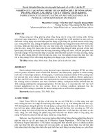
Attenuation
•The energy E transmitted outwards from a source becomes distributed over a
From Kearey et al., 2002
spherical shell
•If the radius of the wavefront is r, the amount of energy contained within a unit area
of the shell is E/4πr2.
•With increasing distance along a ray path, the energy contained in the ray falls
of as r--2 due to geometrical spreading of the energy.
•Wave amplitude, which is proportional to the square root of the wave energy,
falls of as r-1.
Attenuation
•The ground is imperfectly elastic – energy is gradually absorbed by internal
frictional losses
•Absorption coefficient: proportion of energy lost during transmission through
a distance equivalent to a complete wavelength – (dB λ-1).
•Absorption coefficient is usually assumed to be independent of frequency.
•Higher frequency waves therefore attenuate more rapidly than lower
frequency waves as a function of time or distance.
From Kearey et al., 2002
•Absorption produces a progressive lengthening of the seismic pulse.
Attenuation
1. A 10 Hz seismic wave travelling at 5 km s-1 propagates for 1000 m through a
medium with an absorption coefficient of 0.2 dB λ-1. What is the wave
attenuation in dB due solely to absorption?
2. Repeat the above exercise for a 231 Hz seismic wave.
3. Comment on the differences.
1. λ=5000/10 = 500 m. Attenuation = 1000/500 * 0.2 = 0.4 dB
2. λ=5000/231 = 21.65 m. Attenuation = 1000/21.65 * 0.2 = 9.24 dB
Reflection and Transmission
From Kearey, Brooks, and Hill, 2002
•The total energy of a transmitted and reflected ray must equal the energy of the
incident ray
•The relative proportions are determined by the acoustic impedance – the
product of density (ρ) and velocity (v):
Z = vρ
•Generally speaking, the “harder” the rock the greater its acoustic impedance.
•Acoustic impedance contrast is the important factor.
•Maximum transmission of seismic energy requires a matching of acoustic
impedances.
•Reflection coefficient R is a numerical measure of the effect of an interface on
wave propagation. It is the ratio if the amplitude A1 if the reflected ray to the
amplitude A0 of the incident ray:
R=
A1
A0
Expanding, this becomes (for a normally incident ray):
R=
ρ 2 v2 − ρ 1v1 Z 2 − Z1
=
ρ 2 v2 + ρ1v1 Z 2 + Z1
•A negative value of R indicates a 180o phase change in the reflected ray.
•The transmission coefficient T is the ratio of the amplitude A2 of the transmitted
ray to the amplitude A0 of the incident ray:
T=
A2
2 Z1
for a normally incident ray this becomes T =
A0
Z 2 + Z1
From Kearey, Brooks, and Hill, 2002
Reflection and Transmission
Reflection and Transmission
•If R = 0, all the incident energy is transmitted.
•There is no acoustic impedance contrast
•Velocity and density of the layers may still be different.
From Goodliffe et al., 2001
Review: Snell’s Law
As BB’ and AA’ are in proportion to the velocities v1 and v2, the equation can be
rearranged to
sin i1 sin i2
=
v1
v2
Snell’s Law
From Mussestt and Khan, 2000
sin 37 o sin i2
=
4
5
5
sin i2 = sin 37 o
4
So i2 = 48.8o
Vertical Resolution
•
•
•
•
•
•
•
•
Dependant on seismic wavelength
Wedge tests
Individual reflectors clearly resolved when separated by > λ/4
v=f λ
If v = 2000 m/s, and f = 30 Hz
– Resolution = (66.67 m)/4 = 16.67 m
If v = 8000 m/s and f = 20 Hz
– Resolution = (400 m)/4 = 100 m
If v = 2000 m/s and f = 3500 Hz
– Resolution = (0.5714 m)/4 = 0.1428 m
Reflectors thicker than λ/10 can generally be resolved.
Horizontal Resolution
•
•
•
•
•
•
Partly determined by distance between traces
Also dependant on wavelength
Parts of a reflector separated by less than the width of the Fresnel zone will
not be resolved
Wf ≈ (2z λ)1/2 z = depth
If depth = 2000 m, λ = 60 m
– Wf ≈ 490 m
If depth = 100 m, λ = 1 m
– Wf ≈ 14 m
Seismic Sources
Electrical Sources: Sparker
•A spark is produced by the discharge of a high voltage capacitor bank through an
underwater electrode
•Produces a rapidly expanding bubble of ionized gas
Electrical Sources: Boomer
•
•
•
•
•
•
Aluminum plate attached via a spring loaded mount to a resin block
Heavy duty coil is embedded in the resin block
A capacitor bank is discharged through the coil, setting up eddy currents in
the aluminum plate
The currents set up a secondary field that opposes the primary field, and
the plate is repulsed.
Typically a high frequency source, with resolution of ~0.1 m
Depth penetration <100 m
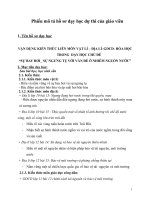
Ready
The lower control chamber has a top
diameter that's smaller than its bottom
diameter, so the air pressure there makes
the piston want to retract (downwards),
sealing the upper, firing chamber. High
pressure air is filling the firing chamber
through the T-shaped passage, and the
firing, or actuating air passage is blocked
(solid black) by a solenoid valve.
Fire!
Now, full pressure has built up in the
upper chamber. The Solenoid has
been triggered, releasing highpressure air into the active air
passage, which is now yellow. The
air fills the area directly below the
piston, overcoming the sealing
effect of the air in the lower, control
chamber. The piston starts to move
upwards, releasing the air in the
upper chamber into the surrounding
water.
From: />
High Pressure Air
Sources: The Air Gun
Fired
The sound source has activated. A large
bubble of compressed air is expanding
into the surrounding water. The air in the
lower control chamber has been
compressed by the upward movement of
the piston. The triggered air, released into
the space below the piston, is fully
expanded, and can now exhaust at a
controlled rate through the vent ports. As
this takes place, the piston rapidly but
gently moves downward, re-sealing the
chamber, and readying the sound source
for refilling.
Air Guns
•Bolt Air gun
From Kearey, Brooks, and Hill, 2002
•The most common marine seismic
source
•Very Repeatable signal
Air Guns
•Airguns suspended from stowed
booms
•Single Air gun – note air ports
The Ideal Shot
•An ideal pulse convolved with the seafloor creates a simple seismogram
Reality
•The output seismogram is a convolution of the source signal and the earth
(the seafloor)
•Sharp seafloor signal becomes “ringy”