VẬT lý địa CHẤN magnetic
Bạn đang xem bản rút gọn của tài liệu. Xem và tải ngay bản đầy đủ của tài liệu tại đây (2.03 MB, 35 trang )
Magnetic Surveying
The investigation of the subsurface ‘geology’ on the basis of anomalies in the
Earth’s magnetic field resulting from the magnetic properties of the causative body.
•A broad range of applications
•Magnetic surveys can be performed on land, at sea, in the air, and on ice.
•Very cheap to perform.
Within the vicinity of a bar magnet a magnetic flux is
developed which flows from one end of the magnet to
the other.
From Kearey, Brooks, and Hill, 2002
Basic Concepts
•Poles are where the flux lines converge.
•The pole of the compass/magnet which points in the
direction of the Earth’s north pole is called the northseeking pole, or positive pole.
•This is balanced by a south-seeking or negative pole
of identical strength at the opposite end of the
magnet.
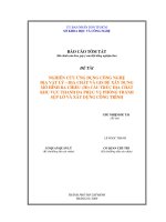
•The Earth’s magnetic field can be crudely
modeled as a bar magnet with it’s south pole at
the Earth’s north magnetic pole.
From Mussett and Khan, 2000
•Mapped from the directions assumed by a small
compass needle, or bar magnet suspended within the
field.
Basic Concepts
The force F between two magnetic poles of strengths m1 and m2 separated by a
distance r is given by:
µ mm
F = 0 1 22
4πµ R r
Where μ0 and μR are constants corresponding to the magnetic permeability of a
vacuum and the relative magnetic permeability of the medium separating the
poles. The force is attractive if the poles are of different sign, and repulsive if they
are of like sign.
The magnetic field B due to a pole of strength m at a distance r from the pole is
defined as the force exerted on a unit positive pole at that point:
µ0 m
B=
4πµ R r 2
The magnetic field can be defined in terms of the magnetic potential in a similar
manner to gravitational fields. For a single pole of strength m, the magnetic
potential V at a distance r from the pole is given by
µm
V= 0
4πµ R r
The magnetic field component in any direction is then given by the partial derivative of
the potential in that direction.
Basic Concepts
In the SI (what is this??) system of units, magnetic parameters are defined in terms
of the flow of electrical current.
•If a current is passed through a coil consisting of several turns of wire, a magnetic
flux flows through and around the coil annulus which arises from a magnetizing
force H.
•The magnitude of H is proportional to the number of turns in the coil and the
strength of the current, and inversely proportional to the length of the wire. H is
expressed in A m-1.
•B is proportional to H. The constant of
proportionality μ is know as the magnetic
permeability.
From Mussett and Khan, 2000
•The density of the magnetic flux, measured over an area perpendicular to the
direction of flow, is known as the magnetic induction, or magnetic field, B.
Basic Concepts
•Lenz’s law of induction relates the rate of change of magnetic flux in a circuit to the
voltage developed within it, so B is expressed in V s m-2 (Weber (Wb) m-2).
•The unit of the Wb m-2 is designated the tesla (T).
•Permeability is expressed in Wb A-1 m-1 or Henry (H) m-1.
•The tesla is too large to express the small magnetic anomalies on the Earth’s
surface. Consequently, the nannotesla is used (1 nT = 10-9 T).
Basic Concepts
•The magnetic moment of a dipole with poles of
strength m a distance l apart is:
M = ml
•The magnetic moment of a current carrying coil is
proportional to the number of turns in the coil, its
cross sectional area, and the magnitude of the
current. The magnetic moment is expressed in A m-2.
•When a material is placed in a magnetic field it may
acquire a magnetization in the direction of the field
which is lost when it is removed.
•This is called Induced Magnetization and results
from the alignment of elementary dipoles within the
material in the direction of the field.
From Kearey, Brooks, and Hill, 2002
•Magnets exhibit a pair of pole – dipoles.
•The intensity of induced magnetization Ji of a material is
defined as the dipole moment per unit volume of material:
M
Ji =
LA
•Where M is the magnetic moment of a sample of length L
and cross-sectional area A. Ji is expressed in A m-1.
•The induced intensity of magnetization is proportional to
the strength of the magnetizing force H of the inducing
field:
J i = kH
Where k is the magnetic susceptibility of the material. As Ji and H are both
measured in A m-1, k is dimensionless.
From Kearey, Brooks, and Hill, 2002
Basic Concepts
Basic Concepts
•In a vacuum the magnetic field strength B and magnetizing force H are related by:
B = µ0 H
Where μ0 is the permeability of a vacuum (4π*10-7 H m-1).
•As air and water have very similar permeabilities to μ0 the relationship can be
taken to represent the Earth’s magnetic field when it is undisturbed.
•When a magnetic material is placed in the field, the resulting magnetization gives
rise to an additional magnetic field in the region occupied by the material, whose
strength is given by:
µ0 J i
Within the body the total magnetic field, B, is given by:
B = µ0 H + µ0 J i
Substituting the relationship with the magnetic susceptibility from the previous
slide gives:
B = µ 0 H + µ 0 kH = (1 + k ) µ 0 H = µ R µ 0 H
Where μR is a dimensionless constant known as the relative magnetic permeability.
The magnetic permeability is thus equal to the product of the relative permeability
and the permeability of vacuum.
Basic Concepts
•All substances are magnetic at an atomic scale.
•Each atom acts as a dipole due to both the spin of its electrons and the orbital
path of its electrons around the nucleus.
•Diamagnetic materials: All electron shells are full and no unpaired electrons
exist. When placed in a magnetic field the orbital paths of the electrons rotate so
as to produce an opposing magnetic field. Magnetic susceptibility is weak and
negative.
•Paramagnetic materials: Electron shells are incomplete, creating a magnetic
field from the spin of the unpaired electrons. When placed in a magnetic field the
dipoles corresponding to the unpaired electron spins rotate to produce a field in
the same sense as the applied field. The susceptibility is positive, but still weak.
•In small grains of certain paramagnetic substances whose atoms contain
several unpaired electrons, the dipoles associated with the spins of the unpaired
electrons are magnetically couples between adjacent atoms. Such a grain is said
to constitute a single magnetic domain. This coupling may be either parallel or
antiparallel.
Basic Concepts
•Antiferromagnetism: Dipole coupling is antiparallel,
with equal numbers of dipoles in each direction. The
magnetic fields of the dipoles cancel out. Defects may
give rise to a small positive magnetization (parasitic
antiferromagnetism). Haematite.
•Ferrimagnetism: The dipole coupling is antiparallel,
but the strengths in each direction are unequal. Strong
spontaneous magnetization, high susceptibility.
Magnetite. Virtually all minerals responsible for the
magnetic properties is common rock types fall into this
category.
From Kearey, Brooks, and Hill, 2002
•Ferromagnetic: Dipoles are parallel. Strong
spontaneous magnetization which can exist in the
absence of an external magnetic field. Iron, cobalt,
nickel. Rarely occur naturally in the Earth’s crust.
Basic Concepts
•Curie Temperature: Above this temperature ferromagnetic and ferrimagnetic
materials loose their magnetization. Interatomic distances are increased to
separations which preclude electron coupling and the material behaves as if
paramagnetic.
•Magnetite has a Curie temperature of 578oC.
•Why might the curie temperature be important?
•Magnetic Domains: Grains may subdivide into domain, where all the dipoles are
aligned.
•When a weak magnetic field is applied, domains magnetized in the direction
of the field grow at the expense of others. When the field is removed, the
domains go back to their original configuration.
•When a strong magnetic field is applied, domains can grow irreversibly
across small imperfections in the grain. The domains are now permanently
enlarged. When the external field is removed, a remnant magnetization
remains.
Remnant Magnetization
•Primary remnant magnetization:
•Acquired as an igneous rock cools through the Curie temperatures of its
constituent minerals (thermoremnant magnetization, TRM).
•Acquired as magnetic particles of a sediment align with the Earth’s magnetic
field while settling (detrital remnant magnetization, DRM).
•Secondary remnant magnetization:
•Recrystallization of minerals during diagenesis of metamorphism (chemical
remnant magnetization, CRM).
•Slow relaxation of domains in an ambient magnetic field (viscous remnant
magnetization, VRM).
Remnant
Magnetization
Rock magnetization has two parts:
•Induced magnetization exists only while a magnetic field exists and is aligned
in the direction of the field. The strength of magnetization is proportional to the
strength of the field and to its magnetic susceptibility.
•Remnant magnetization can exists largely irrespective of the direction of the
magnetic field. It may have a direction very different to the field of today.
Why??
•Total magnetization is the addition of the induced and remnant magnetization
taking into account their directions.
From Mussett and Khan, 2000
•Ratio of remnance to induced magnetizations is the Könisberger ratio, Q. To
further complicate matters, Q may vary through a body.
Susceptibility
•Susceptibility is usually a function of
magnetite content.
•Basic igneous rocks are usually
highly magnetic due to their high
magnetite content.
•Magnetite content decreases with
increasing acidity.
•Granite is generally less magnetic
than basalt.
•Lots of overlap, impossible to
interpret lithology.
Geomagnetic Field
From Kearey, Brooks, and Hill, 2002
From Mussett and Khan, 2000
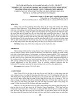
At any point on the earth a freely suspended magnet will assume a position in
space in the direction of the ambient geomagnetic field.
The total field vector, B, has a vertical component Z and a horizontal component
H in the direction of magnetic north.
•Inclination = Dip of B.
•Declination = angle between magnetic north and true north.
B varies in strength from 25,000 nT in equatorial regions to 70,000 nT at the
poles.
Geomagnetic Field
From Mussett and Khan, 2000
•About 90% of the Earth’s magnetic field can be represented by a theoretical
magnetic dipole at the center of the Earth and inclined 11.5o to the axis of rotation.
•If this dipole field is subtracted from the observed magnetic field, the residual
can be modeled by the effects of a second, smaller, dipole.
•This can be repeated again and again until the magnetic field of the Earth has
been modeled with sufficient accuracy.
•The effects of each fictitious dipole contribute to a function known as a
harmonic.
•The technique of successive approximations of the observed field is known as
spherical harmonic analysis.
Geomagnetic Field
•Spherical harmonic analysis is used to compute the formula of the International
Geomagnetic Reference Field (IGRF).
•The IGRF defines the theoretical undisturbed magnetic field at any point on the
Earth’s surface.
•The geomagnetic field cannot in fact result from a series of superimposed bar
magnets. Why?
•The dipolar magnetic moments are far greater than is realistic.
•The prevailing temperatures are far in excess of the Curie temperatures of any
magnetic material.
•Dynamo – the magnetism is believed to be caused by the dynamo action
produced by the circulation of charged particles in coupled convective cells within
the fluid outer core.
•The exchange of dominance between convective cells is believed to produce
the periodic changes in the polarity of the geomagnetic field.
Secular Variation
•The circulation patterns within the outer core are not fixed and change slowly with
time.
•Slow, progressive, temporal change in all geomagnetic elements.
•This has been recorded historically at observatories globally.
•Accordingly, the correction to convert a compass reading to true north has to
be changed every few years (and according to location).
•If we look at the magnetism of old rocks
we see that the magnetic axis wobbles
about the rotation axis.
•A full rotation takes ~2,000 years.
•When averaged over >10,000 years, the
pole is close to axis of rotation.
From Mussett and Khan, 2000
•Maps give both the declination and the rate of change.
Diurnal Variations
Magnetic effects of external origin cause the geomagnetic field to vary on a daily
basis. What might these be??
•Under normal conditions the diurnal variation is smooth, regular, and has an
amplitude of 20-80 nT (maximum at the poles).
•Caused by magnetic field induced by the flow of charged particles within the
ionosphere towards the magnetic poles as both the circulation patterns and
diurnal variations vary in sympathy with the tidal effects of the Sun and Moon.
•On disturbed days the diurnal variation is irregular, with short term disturbances
of up to 1000 nT.
•Magnetic storms resulting from intense solar activity and the arrival in the
ionosphere of charge solar particles.
•Makes magnetic surveying difficult if not impossible.
The normal geomagnetic field can be described by a vector with vertical and
horizontal components:
From Kearey, Brooks, and Hill, 2002
Magnetic Anomalies
B2 = H 2 + Z 2
A magnetic anomaly is now superimposed on the Earth’s field causing a change
ΔB in the strength of the total field vector B. The anomaly produces a vertical
component ΔZ and a horizontal component ΔH at an angle α to H.
Only that part of ΔH in the direction of H, namely ΔH’ will contribute to the
anomaly:
∆H ' = ∆H cos α
The product of the ambient geomagnetic field and the anomaly is thus:
( B + ∆B ) 2 = ( H + ∆H ' ) 2 + ( Z + ∆Z ) 2
Magnetic Anomalies
This previous equation, with a couple of other steps, can be rewritten as:
We can now calculate the anomaly caused by a small isolated magnetic pole of
strength m, defined as the effect of this pole on a unit positive pole at the
observation point. This pole is at depth z, a horizontal distance x and radial
distance r from the observation point. The force of repulsion ΔBr on the unit
positive pole in the direction r is given by:
Cm
µ
∆Br = 2
where C = 0 (assuming µ R = 1)
r
4π
If we assume that the profile lies in the direction of magnetic north so that the
horizontal component of the anomaly lies in this direction, the horizontal (ΔH)
and vertical (ΔZ) components can be computed by resolving in the different
directions:
Cm
Cmx
∆H = 2 cosθ = 3
r
r
− Cm
− Cmz
∆Z = 2 sin θ =
r
r3
From Kearey, Brooks, and Hill, 2002
∆B = ∆Z sin I + ∆H cos I cos α
Magnetic Anomalies
Cm
Cmx
cos
θ
=
r2
r3
− Cm
− Cmz
∆Z = 2 sin θ =
r
r3
•The vertical field anomaly is negative as,
by convention, the z-axis is positive
downwards.
•The horizontal field anomaly is a
positive/negative couplet and the vertical
field anomaly is centered over the pole.
From Kearey, Brooks, and Hill, 2002
∆H =
By substitution, we can now find the total field anomaly ΔB, where α = 0. If the
profile is not in the direction of magnetic north, the angle α would represent the
angle between magnetic north and the profile direction.
∆B = ∆Z sin I + ∆H cos I cos α
Magnetic Anomalies
•A magnetic dipole produces a field
shown by the dashed lines, whose
directions and magnitudes at the
surface are shown by the arrows.
•The anomaly is dependant on the
direction of magnetization of the
body.
From Mussett and Khan, 2000
•The actual field at the Earth’s
surface is found by vector addition
of the field due to the body and the
Earth’s field.
Flux-Gate Magnetometer
•Primary coils are wound around each bar in opposite
directions. Alternating current flows through the primary coils,
producing a changing magnetic field.
•This induces a current in the secondary coil, which is wound
around both bars.
•Because the primary coils are wound in opposite senses their
fields are opposite in direction and cancel. Therefore the
induced current is zero.
•In the presence of an external field it will add to, then subtract
from, the field if the magnetizing coil as the current alternated.
•The fields experienced by the two bars are no longer equal –
the bar in which the field of the coil and the Earth add reaches
saturation sooner. The induced voltages are now out of phase.
•The magnitude of the voltage induced in the secondary coil is
proportional to the amplitude of the external field.
From Kearey, Brooks, and Hill, 2002
•Sensor has 2 identical bars of magnetic material.
Flux-Gate Magnetometer
•Can measure Z or H by aligning the coils in that direction.
•Requires the orientation to be within 11 seconds of arc to achieve a reading
accuracy of 1 nT.
•This accuracy is hard to maintain in a mobile instrument.
•Instead, the total magnetic field is measured.
•Can be measured to an accuracy of 1 nT with far less precise orientation as
the field changes more slowly as a function of orientation about the total field
direction.
•Airborne versions employ orienting mechanisms of various types to maintain
the axis of the instrument in the direction of the geomagnetic field.
•Is not an absolute instrument, may require correction for drift and temperature
effects.