Experimental Invetigation Of Machining Parameters For EDM Using U-Shaped Electrode Of AISI P20 Tool Steel
Bạn đang xem bản rút gọn của tài liệu. Xem và tải ngay bản đầy đủ của tài liệu tại đây (1.16 MB, 72 trang )
A THESIS SUBMITTED IN PARTIAL FULFILMENT
OF THE REQUIREMENTS FOR THE DEGREE OF
Master of Technology
In
Mechanical Engineering
By
SHAILESH KUMAR DEWANGAN
Department of Mechanical Engineering
National Institute of Technology
Rourkela (India)
2010
Experimental Investigation of Machining Parameters for EDM
Using U-shaped Electrode of AISI P20 Tool Steel
A THESIS SUBMITTED IN PARTIAL FULFILMENT
OF THE REQUIREMENTS FOR THE DEGREE OF
Master of Technology
In
Mechanical Engineering
By
SHAILESH KUMAR DEWANGAN
UNDER THE GUIDANCE OF
Dr. C.K. BISWAS
Department of Mechanical Engineering
National Institute of Technology
Rourkela (India)
National Institute of Technology
Rourkela (India)
CERTIFICATE
This is to certify that thesis
thes
entitled, “EXPERIMENTAL
EXPERIMENTAL INVESTIGATION OF
MACHINING PARAMETERS FOR EDM USING U
U-SHAPED ELECTRODE OF AISI
P20 TOOL STEEL ” submitted by Mr. SHAILESH KUMAR DEWANGAN in partial
fulfillment of the requirements for the award of Master of Technology in Mechanical
Engineering with “Production Engineering” Specialization during session 2009-2010
2
in the
Department of Mechanical Engineering National Institute of Technology, Rourkela.
It is an authentic
hentic work carried out by him under my supervision and guidance. To the best of my
knowledge, the matter embodied in this thesis has not been
be
submitted to any other
University/Institute
nstitute for award of any Degree or Diploma.
Date
Dr. C. K. Biswas
Associate Professor
Department of Mechanical Engineering
National institute of technology,
technology Rourkela
i
Acknowledgement
I express my deep sense of gratitude and indebtedness to my thesis supervisor Dr. C. K.
Biswas, Associate Professor, Department of Mechanical Engineering for providing precious
guidance, inspiring discussions and constant supervision throughout the course of this work. His
timely help, constructive criticism, and conscientious efforts made it possible to present the work
contained in this thesis.
I express my sincere thanks to Mr. Mohan Kumar Pradhan, Research Scholar and Mr. K.
Nayak, Technical Assistance in Production Engineering lab. I am grateful to Prof. R. K. Sahoo,
Head of the Department of Mechanical Engineering for providing me the necessary facilities in
the department. I express my sincere gratitude to Prof. S.S. Mahapatra, coordinator of M.E.
course for his timely help during the course of work. I am also thankful to all the staff members
of the department of Mechanical Engineering and to all my well wishers for their inspiration and
help. And also to thanks my classmate’s Jaikishan Pandri, A Prabhkar and Banu Kiran during the
help my project.
I feel pleased and privileged to fulfill my parent’s ambition and I am greatly indebted to them
for bearing the inconvenience during my M Tech. course.
Date
Shailesh kumar Dewangan
Roll No. 208ME202
ii
ABSTRACT
The correct selection of manufacturing conditions is one of the most important aspects to
take into consideration in the majority of manufacturing processes and, particularly, in processes
related to Electrical Discharge Machining (EDM). It is a capable of machining geometrically
complex or hard material components, that are precise and difficult-to-machine such as heat
treated tool steels, composites, super alloys, ceramics, carbides, heat resistant steels etc. being
widely used in die and mold making industries, aerospace, aeronautics and nuclear industries.
AISI P20 Plastic mould steel that is usually supplied in a hardened and tempered condition.
Good machinability, better polishability, it has a grooving rang of application in Plastic moulds,
frames for plastic pressure dies, hydro forming tools These steel are categorized as difficult to
machine materials, posses greater strength and toughness are usually known to create major
challenges during conventional and non- conventional machining. The Electric discharge
machining process is finding out the effect of machining parameter such as discharge current,
pulse on time and diameter of tool of AISI P20 tool steel material. Using U-shaped cu tool with
internal flushing. A well-designed experimental scheme was used to reduce the total number of
experiments. Parts of the experiment were conducted with the L18 orthogonal array based on the
Taguchi method. Moreover, the signal-to-noise ratios associated with the observed values in the
experiments were determined by which factor is most affected by the Responses of Material
Removal Rate (MRR), Tool Wear Rate (TWR) and over cut (OC).
iii
Contents
Page no.
CERTIFICATE
i
ACKNOWLEDGEMENT
Ii
ABSTRACT
Iii
CONTENTS
iv
LIST OF FIGURES
vii
LIST OF TABLES
viii
CHAPTER-1 INTRODUCTION
1
1.1
Background of Electric discharge machine (EDM)
1
1.2
Introduction of EDM
2
1.3
Principle of EDM
2
1.4
Types of EDM
4
1.4.1
Die-sinking
4
1.4.2
Wire cut EDM
5
1.5
Important parameters of EDM
6
1.6
Characteristics of EDM
7
1.7
Dielectric fluid
8
1.8
Flushing method
8
1.9
Tool Material
9
1.10
Design variable
10
1.11
Workpiece material
11
1.12
Application of EDM
11
1.13
Advantages of EDM
12
1.14
Limitation of EDM
13
iv
CHAPTER- 2 LITERATURE SURVEY
14
2.1
Workpiece and tool material of EDM
14
2.2
EDM with tubular electrode
20
2.3
EDM tool design
21
2.4
Effect of multiple discharges of EDM
22
2.5
EDM with CNC
23
2.6
Objective of the present work
26
CHAPTER -3 EXPERIMENTAL WORKS
3.1
27
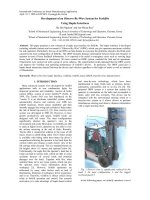
Experimental set up
27
3.1.1 Dielectric reservoir, pump and circulation system
28
3.1.2 Power generator and control unit
28
3.1.3 Working tank with work holding device
29
3.1.4 X-Y table accommodating the working table
29
3.1.5 The tool holder
29
3.1.6 The servo system to feed the tool.
30
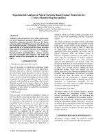
3.2
Section of the work piece
30
3.3
Tool design
32
3.4
Flow chart of experiment
34
3.5
Mechanism of Material removal rate
35
3.5.1
35
3.6
Evaluation of MRR
Mechanism of Tool wears
36
3.6.1 Evaluation of TWR
36
Mechanism of over cut
36
3.7.1 Evaluation of over cut
37
3.8
Taguchi design
37
3.9
Taguchi design experiments in MINITAB
37
3.7
3.10 Conduct of Experiment
38
3.11 Design matrix and observation table
39
v
3.12 Conclusion
CHAPTER -4 RESULTS AND DISCUSSION
40
41
4.1 Response Table
41
4.2 Influences on MRR
42
4.2.1 Model Analysis of MRR
4.3 Influences of TWR
4.3.1 Model Analysis of TWR
4.4 Influences of Over cut
4.4.1 Model Analysis of OC
45
46
49
50
53
CHAPTER - 5 CONCLUSIONS
55
CHAPTER – 6 APPENDIX
56
CHAPTER- 7 REFERENCES
61
CHAPTER- 8 BIBLIOGRAPHY
68
vi
LIST OF FIGURES
Figure no. Title
Page no.
1.1
Set up of Electric discharge machining
3
1.2
Working principle of EDM process
4
1.3
Die sinking & wire cut EDM Process
6
1.4
Flushing of U-tube Cu electrode
9
2.1
Graph between interactive effect of Sic and Current on MRR
15
2.2
Multi Response optimization for Max. MRR and Min.TWR
15
2.3
MRR and surface roughness with pulse duration graph
16
2.4
Design of Cu ring tool shaped B-EDM
18
2.5
Experimental set-up
20
2.6
Solid model of workpiece and interference between work and tool
23
2.7
Compensation for wear during scanning of a layer
25
3.1
Dielectric reservoirs
28
3.2
Control unit of EDM machine
29
3.3
Tool holder with Workpiece and tool
29
3.4
P20 Workpiece and Cu U-shaped tool
32
3.5
U - Tube Copper tool design
33
3.6
U-shaped Copper tool
33
3.7
Crater formation in EDM process
35
4.1
Main effect plot for MRR
44
4.2
Interaction plot for MRR
44
4.3
Residual plot for MRR
46
4.4
Main effect plot for TWR
48
4.5
Interaction plot for TWR
48
4.6
Residual plot for TWR
50
4.7
Main effect plot for over cut
52
4.8
Interaction plot for over cut
52
4.9
Residual plot for over cut
54
5.1
Die Sinker EDM Model: PS 50ZNC
56
vii
5.2
Electronic Balance weight machine
57
5.3
Tool maker microscope
57
viii
LIST OF TABLES
Table no.
Title
Page no.
1.1
Specification on EDM
7
3.1
Composition of AISI P-20 tool steel material
30
3.2
AISI P20 Steel categories
31
3.3
Mechanical properties of P20 steel
31
3.4
Thermal properties of P20 steel
31
3.5
Machining parameters and their level
38
3.6
Design matrix and observation Table
39
4.1
Response table
41
4.2
ANOVA for S/N Ratios (MRR)
42
4.3
Response for S/N Ratios Larger is better (MRR)
43
4.4
Estimation model for Coefficient (MRR)
45
4.5
ANOVA for S/N Ratios (TWR)
47
4.6
Response for S/N Ratios smaller is better (TWR)
47
4.7
Estimation model for Coefficient (TWR)
49
4.8
ANOVA for S/N Ratios (over cut)
51
4.9
Response for S/N Ratios smaller is better (over cut)
51
4.10
Estimation model for Coefficient (over cut)
53
ix
Chapter 1
1.1 Background of EDM
The history of EDM Machining Techniques goes as far back as the 1770s when it was
discovered by an English Scientist. However, Electrical Discharge Machining was not fully
taken advantage of until 1943 when Russian scientists learned how the erosive effects of the
technique could be controlled and used for machining purposes.
When it was originally observed by Joseph Priestly in 1770, EDM Machining was very
imprecise and riddled with failures. Commercially developed in the mid 1970s, wire EDM began
to be a viable technique that helped shape the metal working industry we see today. In the mid
1980s.The EDM techniques were transferred to a machine tool. This migration made EDM more
widely available and appealing over traditional machining processes.
The new concept of manufacturing uses non-conventional energy sources like sound,
light, mechanical, chemical, electrical, electrons and ions. With the industrial and technological
growth, development of harder and difficult to machine materials, which find wide application in
aerospace, nuclear engineering and other industries owing to their high strength to weight ratio,
hardness and heat resistance qualities has been witnessed. New developments in the field of
material science have led to new engineering metallic materials, composite materials and high
tech ceramics having good mechanical properties and thermal characteristics as well as sufficient
electrical conductivity so that they can readily be machined by spark erosion. Non-traditional
machining has grown out of the need to machine these exotic materials. The machining
processes are non-traditional in the sense that they do not employ traditional tools for metal
removal and instead they directly use other forms of energy. The problems of high complexity in
shape, size and higher demand for product accuracy and surface finish can be solved through
non-traditional methods. Currently, non-traditional processes possess virtually unlimited
Page 1
capabilities except for volumetric material removal rates, for which great advances have been
made in the past few years to increase the material removal rates. As removal rate increases, the
cost effectiveness of operations also increase, stimulating ever greater uses of nontraditional
process. The Electrical Discharge Machining process is employed widely for making tools, dies
and other precision parts.
EDM has been replacing drilling, milling, grinding and other traditional machining
operations and is now a well established machining option in many manufacturing industries
throughout the world. And is capable of machining geometrically complex or hard material
components, that are precise and difficult-to-machine such as heat treated tool steels, composites,
super alloys, ceramics, carbides, heat resistant steels etc. being widely used in die and mold
making industries, aerospace, aeronautics and nuclear industries. Electric Discharge Machining
has also made its presence felt in the new fields such as sports, medical and surgical,
instruments, optical, including automotive R&D areas.
1.2 Introduction of EDM Electro Discharge Machining (EDM) is an electro-thermal non-traditional machining
Process, where electrical energy is used to generate electrical spark and material removal mainly
occurs due to thermal energy of the spark.
EDM is mainly used to machine difficult-to-machine materials and high strength
temperature resistant alloys. EDM can be used to machine difficult geometries in small batches
or even on job-shop basis. Work material to be machined by EDM has to be electrically
conductive.
1.3 Principle of EDM –
In this process the metal is removing from the work piece due to erosion case by rapidly
recurring spark discharge taking place between the tool and work piece. Show the mechanical set
up and electrical set up and electrical circuit for electro discharge machining. A thin gap about
0.025mm is maintained between the tool and work piece by a servo system shown in fig 1.1.
Both tool and work piece are submerged in a dielectric fluid .Kerosene/EDM oil/deionized water
Page 2
is very common type of liquid dielectric although gaseous dielectrics are also used in certain
cases.
Figure1. 1 Set up of Electric discharge machining
This fig.1.1 is shown the electric setup of the Electric discharge machining. The tool is
mead cathode and work piece is anode. When the voltage across the gap becomes sufficiently
high it discharges through the gap in the form of the spark in interval of from 10 of micro
seconds. And positive ions and electrons are accelerated, producing a discharge channel that
becomes conductive. It is just at this point when the spark jumps causing collisions between ions
and electrons and creating a channel of plasma. A sudden drop of the electric resistance of the
previous channel allows that current density reaches very high values producing an increase of
ionization and the creation of a powerful magnetic field. The moment spark occurs sufficiently
pressure developed between work and tool as a result of which a very high temperature is
reached and at such high pressure and temperature that some metal is melted and eroded.
Such localized extreme rise in temperature leads to material removal. Material removal
occurs due to instant vaporization of the material as well as due to melting. The molten metal is
not removed completely but only partially
Page 3
As the potential difference is withdrawn as shown in Fig. 1.2, the plasma channel is no
longer sustained. As the plasma channel collapse, it generates pressure or shock waves, which
evacuates the molten material forming a crater of removed material around the site of the spark.
Figure1. 2 Working principle of EDM process
1.4 Types of EDM –
Basically, there are two different types of EDM:
1.4.1) Die-sinking
1.4.2) wire-cut.
1.4.1Die-sinking EDM –
In the Sinker EDM Machining process, two metal parts submerged in an insulating liquid
are connected to a source of current which is switched on and off automatically depending on the
parameters set on the controller. When the current is switched on, an electric tension is created
between the two metal parts. If the two parts are brought together to within a fraction of an inch,
the electrical tension is discharged and a spark jumps across. Where it strikes, the metal is heated
up so much that it melts. Sinker EDM, also called cavity type EDM or volume EDM consists of
an electrode and workpiece submerged in an insulating liquid such as, more typically, oil or, less
frequently, other dielectric fluids. The electrode and workpiece are connected to a suitable power
supply. The power supply generates an electrical potential between the two parts. As the
electrode approaches the workpiece, dielectric breakdown occurs in the fluid, forming a plasma
channel, and a small spark jumps.
Page 4
These sparks usually strike one at a time because it is very unlikely that different locations
in the inter-electrode space have the identical local electrical characteristics which would enable
a spark to occur simultaneously in all such locations. These sparks happen in huge numbers at
seemingly random locations between the electrode and the workpiece. As the base metal is
eroded, and the spark gap subsequently increased, the electrode is lowered automatically by the
machine so that the process can continue uninterrupted. Several hundred thousand sparks occur
per second, with the actual duty cycle carefully controlled by the setup parameters.
1.4.2 Wire-cut EDM –
Wire EDM Machining (also known as Spark EDM) is an electro thermal production
process in which a thin single-strand metal wire (usually brass) in conjunction with de-ionized
water (used to conduct electricity) allows the wire to cut through metal by the use of heat from
electrical sparks. a thin single-strand metal wire, usually brass, is fed through the workpiece,
submerged in a tank of dielectric fluid, typically deionized water. Wire-cut EDM is typically
used to cut plates as thick as 300mm and to make punches, tools, and dies from hard metals that
are difficult to machine with other methods.
Wire-cutting EDM is commonly used when low residual stresses are desired, because it
does not require high cutting forces for removal of material. If the energy/power per pulse is
relatively low (as in finishing operations), little change in the mechanical properties of a material
is expected due to these low residual stresses, although material that hasn't been stress-relieved
can distort in the machining process. Due to the inherent properties of the process, wire EDM
can easily machine complex parts and precision components out of hard conductive materials.
Page 5
Figure1. 3 Die sinking & wire cut EDM Process
1.5 Important parameters of EDM
(a) Spark On-time (pulse time or Ton): The duration of time (µs) the current is allowed to
flow per cycle. Material removal is directly proportional to the amount of energy applied
during this on-time. This energy is really controlled by the peak current and the length of
the on-time.
(b) Spark Off-time (pause time or Toff ):
The duration of time (µs) between the sparks
(that is to say, on-time). This time allows the molten material to solidify and to be wash
out of the arc gap. This parameter is to affect the speed and the stability of the cut. Thus,
if the off-time is too short, it will cause sparks to be unstable.
(c) Arc gap (or gap): The Arc gap is distance between the electrode and workpiece during
the process of EDM. It may be called as spark gap. Spark gap can be maintained by servo
system (fig no.-1).
(d) Discharge current (current Ip): Current is measured in amp Allowed to per cycle.
Discharge current is directly proportional to the Material removal rate.
(e) Duty cycle (τ): It is a percentage of the on-time relative to the total cycle time. This
parameter is calculated by dividing the on-time by the total cycle time (on-time pulse offtime).
τ =
୭୬
୭୬ା୭
(f) Voltage (V): It is a potential that can be measure by volt it is also effect to the material
removal rate and allowed to per cycle. Voltage is given by in this experiment is 50 V.
Page 6
(g) Diameter of electrode (D): It is the electrode of Cu-tube there are two different size of
diameter 4mm and 6mm in this experiment. This tool is used not only as a electrode but
also for internal flushing.
(h) Over cut – It is a clearance per side between the electrode and the workpiece after the
marching operation.
1.6 Characteristics of EDM
EDM specification by mechanism of process, metal removal rate and other function that
shown in this table no .1
Table1.1 Specification on EDM
Mechanism of process
Controlled erosion (melting and evaporation) through a
series of electric spark
Spark gap
0.010- 0.500 mm
Spark frequency
200 – 500 kHz
Peak voltage across the gap
30- 250 V
Metal removal rate (max.)
5000 mm3/min
Specific power consumption
2-10 W/mm3/min
Dielectric fluid
EDM oil, Kerosene liquid paraffin, silicon oil, deionized
water etc.
Tool material
Copper, Brass, graphite, Ag-W alloys, Cu-W alloys .
MRR/TWR
0.1-10
Materials that can be machined
All conducting metals and alloys.
Shapes
Microholes, narrow slots, blind cavities
Limitations
High specific energy consumption, non conducting
materials can’t be machined.
Page 7
1.7 Dielectric fluid
In EDM, as has been discussed earlier, material removal mainly occurs due to thermal
evaporation and melting. As thermal processing is required to be carried out in absence of
oxygen so that the process can be controlled and oxidation avoided. Oxidation often leads to
poor surface conductivity (electrical) of the work piece hindering further machining. Hence,
dielectric fluid should provide an oxygen free machining environment. Further it should have
enough strong dielectric resistance so that it does not breakdown electrically too easily but at the
same time ionize when electrons collide with its molecule. Moreover, during sparking it should
be thermally resistant as well.
The dielectric fluid has the following functions:
(a) It helps in initiating discharge by serving as a conducting medium when ionised, and
conveys the spark. It concentrates the energy to a very narrow region.
(b) It helps in quenching the spark, cooling the work, tool electrode and enables arcing to be
prevented.
(c) It carries away the eroded metal along with it.
(d) It acts as a coolant in quenching the sparks.
The electrode wear rate, metal removal rate and other operation characteristics are also
influenced by the dielectric fluid.
The dielectric generally fluid used are transformer on silicon oil, EDM oil, kerosene (paraffin
oil) and de-ionized water are used as dielectric fluid in EDM. Tap water cannot be used as it
ionizes too early and thus breakdown due to presence of salts as impurities occur. Dielectric
medium is generally flushed around the spark zone. It is also applied through the tool to achieve
efficient removal of molten material.
In this experiment using the Commercial grade EDM oil (specific gravity= 0.763, freezing
point= 94˚C) was used as dielectric fluid are used it is using as coolant and medium of workpiece
and tool during the process of erosion.
1.8. Flushing methodFlushing is the most important function in any electrical discharge machining operation.
Flushing is the process of introducing clean filtered dielectric fluid into the spark gap. There are
a number of flushing methods used to remove the metal particles efficiently.
Page 8
This experiment is using the internal flushing with the Cu U- shaped tool shown in the fig
no. 1.4.
Figure 1. 4 Flushing of U-tube Cu electrode
1.9. Tool MaterialTool material should be such that it would not undergo much tool wear when it is impinged
by positive ions. Thus the localized temperature rise has to be less by tailoring or properly
choosing its properties or even when temperature increases, there would be less melting. Further,
the tool should be easily workable as intricate shaped geometric features are machined in EDM.
Thus the basic characteristics of electrode materials are:
1. High electrical conductivity – electrons are cold emitted more easily and there is less bulk
electrical heating.
2. High thermal conductivity – for the same heat load, the local temperature rise would be
less due to faster heat conducted to the bulk of the tool and thus less tool wear.
3. Higher density – for the same heat load and same tool wear by weight there would be less
volume removal or tool wear and thus less dimensional loss or inaccuracy.
4. High melting point – high melting point leads to less tool wear due to less tool material
melting for the same heat load.
5. Easy manufacturability.
Page 9
6. Cost – cheap.
The followings are the different electrode materials which are used commonly in the
industry:
1. Graphite
2. copper
3. Tellurium copper – 99% Cu + 0.5% tellurium
4. Brass
In this experiment are using the Cu tool U-shaped tool with internal flushing system this
tool material can be eroded by U shaped.
1.10. Design variableDesign parameter, process parameter and constant parameter are following ones,
Design parameters –
1. Material removal rate.
2. Tool wear rate
3. Over cut (OC)
Machining parameter –
1. Discharge current (Ip)
2. Pulse on time (Ton)
3. Diameter of U-shaped tool
Constant parameter1. Duty cycle
2. Voltage
3. Flushing pressure
4. Polarity
Page 10
1.11. Workpiece materialIt is capable of machining geometrically complex or hard material components, that
are precise and difficult-to-machine such as heat treated tool steels, composites, super alloys,
ceramics, carbides, heat resistant steels etc.
There are different types of tool material are using the EDM method. And the tool steel
contains carbon and alloy steels that are particularly well-suited to be made into tools. Their
suitability comes from their distinctive hardness, resistance to abrasion, their ability to hold a
cutting edge, and/or their resistance to deformation at elevated temperatures (red-hardness). Tool
steel is generally used in a heat-treated state. Tool steels are made to a number of grades for
different applications. In general, the edge temperature under expected use is an important
determinant of both composition and required heat treatment. The higher carbon grades are
typically used for such applications as stamping dies, metal cutting tools, etc.
In this experiment are using AISI P-20 plastic mould tool steel material.
1.12 Application of EDM –
1. The EDM process is most widely used by the mould-making tool and die industries, but is
becoming a common method of making prototype and production parts, especially in the
aerospace, automobile and electronics industries in which production quantities are relatively
low.
2. It is used to machine extremely hard materials that are difficult to machine like alloys, tool
steels, tungsten carbides etc.
3. It is used for forging, extrusion, wire drawing, thread cutting.
4. It is used for drilling of curved holes.
5. It is used for internal thread cutting and helical gear cutting.
6. It is used for machining sharp edges and corners that cannot be machined effectively by other
machining processes.
Page 11
7. Higher Tolerance limits can be obtained in EDM machining. Hence areas that require higher
surface accuracy use the EDM machining process.
8. Ceramic materials that are difficult to machine can be machined by the EDM machining
process.
9. Electric Discharge Machining has also made its presence felt in the new fields such as sports,
medical and surgical, instruments, optical, including automotive R&D areas.
10. It is a promising technique to meet increasing demands for smaller components usually
highly complicated, multi-functional parts used in the field of micro-electronics.
1.13 Advantages of EDM
(a) Any material that is electrically conductive can be cut using the EDM process.
(b)
Hardened workpieces can be machined eliminating the deformation caused by heat
treatment.
(c) X, Y, and Z axes movements allow for the programming of complex profiles using simple
electrode.
(d) Complex dies sections and molds can be produced accurately, faster, and at lower costs.
Due to the modern NC control systems on die sinking machines, even more complicated work
pieces can be machined.
(e) The high degree of automation and the use of tool and work piece changers allow the
machines to work unattended for overnight or during the weekends
(f) Forces are produced by the EDM-process and that, as already mentioned, flushing and
hydraulic forces may become large for some work piece geometry. The large cutting forces of
the mechanical materials removal processes, however, remain absent.
(g) Thin fragile sections such as webs or fins can be easily machined without deforming the
part.
Page 12
1.14 Limitation of EDM –
(a) The need for electrical conductivity – To be able to create discharges, the work piece has
to be electrically conductive. Isolators, like plastics, glass and most ceramics, cannot be
machined by EDM, although some exception like for example diamond is known.
Machining of partial conductors like Si semi-conductors, partially conductive ceramics and
even glass is also possible.
(b) Predictability of the gap - The dimensions of the gap are not always easily predictable,
especially with intricate work piece geometry. In these cases, the flushing conditions and
the contamination state of differ from the specified one. In the case of die-sinking EDM,
the tool wear also contributes to a deviation of the desired work piece geometry and it
could reduce the achievable accuracy. Intermediate measuring of the work piece or some
preliminary tests can often solve the problems.
(c) Low material removal rate- The material removal of the EDM-process is rather low,
especially in the case of die-sinking EDM where the total volume of a cavity has to be
removed by melting and evaporating the metal. With wire-EDM only the outline of the
desired work piece shape has to be machined. Due to the low material removal rate, EDM
is principally limited to the production of small series although some specific mass
production applications are known.
(d) Optimization of the electrical parameters - The choice of the electrical parameters of the
EDM-process depends largely on the material combination of electrode and work piece and
EDM manufactures only supply these parameters for a limited amount of material
combinations. When machining special alloys, the user has to develop his own technology.
Page 13
Chapter 2
IntroductionIn this chapter search few selected research paper related to EDM with effect of metal MRR,
TWR, OC, surface roughness (SR) workpiece material, we are broadly classified all the paper in
to five different category, i.e. paper related to material related workpiece or tool, tubular
electrode, tool design, some paper related to Effect of multiple discharge and rest of the paper
related to CNC.
2.1 Workpiece and tool materialDhar and Purohit [1] evaluates the effect of current (c), pulse-on time (p) and air gap voltage
(v) on MRR, TWR, ROC of EDM with Al–4Cu–6Si alloy–10 wt. % SiCP composites. This
experiment can be using the PS LEADER ZNC EDM machine and a cylindrical brass electrode
of 30 mm diameter. And three factors, three levels full factorial design was using and analyzing
the results. A second order, non-linear mathematical model has been developed for establishing
the relationship among machining parameters. The significant of the models were checked using
technique ANOVA and finding the MRR, TWR and ROC increase significant in a non-linear
fashion with increase in current.
Karthikeyan et .al [2] has presented the mathematical molding of EDM with aluminum-silicon
carbide particulate composites. Mathematical equation is Y=f(V, I, T). And the effect of MRR,
TWR, SR with Process parameters taken in to consideration were the current (I), the pulse
duration (T) and the percent volume fraction of SiC (25 µ size). A three level full factorial
design was choosing. Finally the significant of the models were checked using the ANOVA.
The MRR was found to decrease with an increase in the percent volume of SiC, whereas the
TWR and the surface roughness increase with an increase in the volume of Sic. it shown the
graph between interactive effect of the percent volume of Sic and the current on MRR Fig 2.1.
Page 14