Tiêu chuẩn Châu Âu EC4: Kết cấu bê tông cốt thép liên hợp phần 1.2: Kết cấu chịu lửa (Eurocode4 BS EN1994 1 2 e 2005 Design of composite structures part 1.2: General rules and Structural fire design)
Bạn đang xem bản rút gọn của tài liệu. Xem và tải ngay bản đầy đủ của tài liệu tại đây (1.22 MB, 114 trang )
Licensed Copy: x x, University of Glamorgan, Mon Apr 23 19:04:52 GMT+00:00 2007, Uncontrolled Copy, (c) BSI
BRITISH STANDARD
Eurocode 4 — Design of
composite steel and
concrete structures —
Part 1-2: General rules — Structural fire
design
The European Standard EN 1994-1-2:2005 has the status of a
British Standard
ICS 13.220.50; 91.010.30; 91.080.10; 91.080.40
12 &23<,1* :,7+287 %6, 3(50,66,21 (;&(37 $6 3(50,77(' %< &23<5,*+7 /$:
BS EN
1994-1-2:2005
BS EN 1994-1-2:2005
Licensed Copy: x x, University of Glamorgan, Mon Apr 23 19:04:52 GMT+00:00 2007, Uncontrolled Copy, (c) BSI
National foreword
This British Standard is the official English language version of
EN 1994-1-2:2005.
The structural Eurocodes are divided into packages by grouping Eurocodes for
each of the main materials, concrete, steel, composite concrete and steel,
timber, masonry and aluminium; this is to enable a common date of
withdrawal (DOW) for all the relevant parts that are needed for a particular
design. The conflicting national standards will be withdrawn at the end of the
coexistence period, after all the EN Eurocodes of a package are available.
Following publication of the EN, there is a period of two years allowed for the
national calibration period during which the national annex is issued, followed
by a three year coexistence period. During the coexistence period Member
States will be encouraged to adapt their national provisions to withdraw
conflicting national rules before the end of the coexistence period. The
Commission in consultation with Member States is expected to agree the end
of the coexistence period for each package of Eurocodes.
At the end of this coexistence period, the national standard(s) will be
withdrawn.
In the case of BS EN 1994-1-2:2005, there are no corresponding national
standards.
The UK participation in its preparation was entrusted by Technical Committee
B/525, Building and civil engineering structures, to Subcommittee B/525/4,
Composite structures, which has the responsibility to:
—
aid enquirers to understand the text;
—
present to the responsible international/European committee any
enquiries on the interpretation, or proposals for change, and keep
UK interests informed;
—
monitor related international and European developments and
promulgate them in the UK.
A list of organizations represented on this subcommittee can be obtained on
request to its secretary.
Summary of pages
This document comprises a front cover, an inside front cover, page i, a blank
page, the EN title page, pages 2 to 109 and a back cover.
The BSI copyright notice displayed in this document indicates when the
document was last issued.
Amendments issued since publication
This British Standard was
published under the authority
of the Standards Policy and
Strategy Committee
on 5 December 2005
© BSI 5 December 2005
ISBN 0 580 47235 3
Amd. No.
Date
Comments
Licensed Copy: x x, University of Glamorgan, Mon Apr 23 19:04:52 GMT+00:00 2007, Uncontrolled Copy, (c) BSI
BS EN 1994-1-2:2005
Where a normative part of this EN allows for a choice to be made at the national
level, the range and possible choice will be given in the normative text, and a note
will qualify it as a Nationally Determined Parameter (NDP). NDPs can be a
specific value for a factor, a specific level or class, a particular method or a
particular application rule if several are proposed in the EN.
To enable EN 1994-1-2 to be used in the UK, the NDPs will be published in a
national annex, which will be made available by BSI in due course, after public
consultation has taken place.
Cross-references
The British Standards which implement international or European publications
referred to in this document may be found in the BSI Catalogue under the section
entitled “International Standards Correspondence Index”, or by using the
“Search” facility of the BSI Electronic Catalogue or of British Standards Online.
This publication does not purport to include all the necessary provisions of a
contract. Users are responsible for its correct application.
Compliance with a British Standard does not of itself confer immunity
from legal obligations.
i
blank
Licensed Copy: x x, University of Glamorgan, Mon Apr 23 19:04:52 GMT+00:00 2007, Uncontrolled Copy, (c) BSI
EUROPEAN STANDARD
EN 1994-1-2
NORME EUROPÉENNE
Licensed Copy: x x, University of Glamorgan, Mon Apr 23 19:04:52 GMT+00:00 2007, Uncontrolled Copy, (c) BSI
EUROPÄISCHE NORM
August 2005
ICS 13.220.50; 91.010.30; 91.080.10; 91.080.40
Supersedes ENV 1994-1-2:1994
English Version
Eurocode 4 - Design of composite steel and concrete structures
- Part 1-2: General rules - Structural fire design
Eurocode 4 - Calcul des structures mixtes acier-béton Partie 1-2: Règles générales - Calcul du comportement au
feu
Eurocode 4 - Bemessung und Konstruktion von
Verbundtragwerken aus Stahl und Beton - Teil 1-2:
Allgemeine Regeln Tragwerksbemessung im Brandfall
This European Standard was approved by CEN on 4 November 2004.
CEN members are bound to comply with the CEN/CENELEC Internal Regulations which stipulate the conditions for giving this European
Standard the status of a national standard without any alteration. Up-to-date lists and bibliographical references concerning such national
standards may be obtained on application to the Central Secretariat or to any CEN member.
This European Standard exists in three official versions (English, French, German). A version in any other language made by translation
under the responsibility of a CEN member into its own language and notified to the Central Secretariat has the same status as the official
versions.
CEN members are the national standards bodies of Austria, Belgium, Cyprus, Czech Republic, Denmark, Estonia, Finland, France,
Germany, Greece, Hungary, Iceland, Ireland, Italy, Latvia, Lithuania, Luxembourg, Malta, Netherlands, Norway, Poland, Portugal, Slovakia,
Slovenia, Spain, Sweden, Switzerland and United Kingdom.
EUROPEAN COMMITTEE FOR STANDARDIZATION
COMITÉ EUROPÉEN DE NORMALISATION
EUROPÄISCHES KOMITEE FÜR NORMUNG
Management Centre: rue de Stassart, 36
© 2005 CEN
All rights of exploitation in any form and by any means reserved
worldwide for CEN national Members.
B-1050 Brussels
Ref. No. EN 1994-1-2:2005: E
EN 1994-1-2:2005 (E)
Licensed Copy: x x, University of Glamorgan, Mon Apr 23 19:04:52 GMT+00:00 2007, Uncontrolled Copy, (c) BSI
Contents
Foreword
Page
...........................................................................................................................5
Background of the Eurocode programme..................................................................................................5
Status and field of application of Eurocodes .............................................................................................6
National Standards implementing Eurocodes ...........................................................................................6
Links between Eurocodes and harmonised technical specifications (ENs and ETAs) for products.........7
Additional information specific for EN 1994-1-2 ........................................................................................7
National annex for EN 1994-1-2 ..............................................................................................................10
Section 1
1.1
1.2
1.3
1.4
1.5
1.6
Scope ............................................................................................................................................11
Normative references....................................................................................................................13
Assumptions..................................................................................................................................15
Distinction between Principles and Application Rules ..................................................................15
Definitions .....................................................................................................................................15
1.5.1 Special terms relating to design in general…………………… ...........……………………..15
1.5.2 Terms relating to material and products properties...........................................................16
1.5.3 Terms relating to heat transfer analysis ............................................................................16
1.5.4 Terms relating to mechanical behaviour analysis .............................................................16
Symbols ........................................................................................................................................16
Section 2
2.1
2.2
2.3
2.4
3.3
3.4
2
Basis of design ..............................................................................................26
Requirements................................................................................................................................26
2.1.1 Basic requirements ............................................................................................................26
2.1.2 Nominal fire exposure........................................................................................................26
2.1.3 Parametric fire exposure....................................................................................................27
Actions ..........................................................................................................................................27
Design values of material properties ............................................................................................27
Verification methods .....................................................................................................................28
2.4.1 General ..............................................................................................................................28
2.4.2 Member analysis................................................................................................................29
2.4.3 Analysis of part of the structure .........................................................................................30
2.4.4 Global structural analysis...................................................................................................31
Section 3
3.1
3.2
General ...........................................................................................................11
Material properties ........................................................................................31
General .........................................................................................................................................31
Mechanical properties...................................................................................................................31
3.2.1 Strength and deformation properties of structural steel ....................................................31
3.2.2 Strength and deformation properties of concrete ..............................................................33
3.2.3 Reinforcing steels ..............................................................................................................35
Thermal properties........................................................................................................................36
3.3.1 Structural and reinforcing steels ........................................................................................36
3.3.2 Normal weight concrete .....................................................................................................39
3.3.3 Light weight concrete.........................................................................................................41
3.3.4 Fire protection materials ....................................................................................................42
Density ..........................................................................................................................................42
EN 1994-1-2:2005 (E)
Licensed Copy: x x, University of Glamorgan, Mon Apr 23 19:04:52 GMT+00:00 2007, Uncontrolled Copy, (c) BSI
Section 4
4.1
4.2
4.3
4.4
Introduction ...................................................................................................................................43
Tabulated data ..............................................................................................................................44
4.2.1 Scope of application ..........................................................................................................44
4.2.2 Composite beam comprising steel beam with partial concrete encasement ....................45
4.2.3 Composite columns ...........................................................................................................47
Simple Calculation Models............................................................................................................51
4.3.1 General rules for composite slabs and composite beams ................................................51
4.3.2 Unprotected composite slabs ............................................................................................51
4.3.3 Protected composite slabs.................................................................................................52
4.3.4 Composite beams..............................................................................................................53
4.3.5 Composite columns ...........................................................................................................61
Advanced calculation models .......................................................................................................64
4.4.1 Basis of analysis ................................................................................................................64
4.4.2 Thermal response..............................................................................................................65
4.4.3 Mechanical response.........................................................................................................65
4.4.4 Validation of advanced calculation models........................................................................65
Section 5
5.1
5.2
5.3
5.4
Design procedures …………………………………………………………………..43
Constructional details...................................................................................66
Introduction ...................................................................................................................................66
Composite beams .........................................................................................................................66
Composite columns ......................................................................................................................67
5.3.1 Composite columns with partially encased steel sections ................................................67
5.3.2 Composite columns with concrete filled hollow sections...................................................67
Connections between composite beams and columns ................................................................68
5.4.1 General ..............................................................................................................................68
5.4.2 Connections between composite beams and composite columns with steel sections
encased in concrete...........................................................................................................69
5.4.3 Connections between composite beams and composite columns with partially encased
steel sections. ....................................................................................................................70
5.4.4 Connections between composite beams and composite columns with concrete filled
hollow sections ..................................................................................................................70
Annex A (INFORMATIVE)
Annex B (INFORMATIVE)
Stress-strain relationships at elevated temperatures for
structural steels
72
Stress-strain relationships at elevated temperatures for
concrete with siliceous aggregate
75
Annex C (INFORMATIVE)
Concrete stress-strain relationships adapted to natural fires
with a decreasing heating branch for use in advanced
calculation models
77
Annex D (INFORMATIVE)
Model for the calculation of the fire resistance of unprotected
composite slabs exposed to fire beneath the slab according
to the standard temperature-time curve
79
D.1
D.2
D.3
D.4
D.5
Fire resistance according to thermal insulation
Calculation of the sagging moment resistance Mfi,Rd+
Calculation of the hogging moment resistance Mfi,RdEffective thickness of a composite slab
Field of application
79
80
82
84
85
3
EN 1994-1-2:2005 (E)
Licensed Copy: x x, University of Glamorgan, Mon Apr 23 19:04:52 GMT+00:00 2007, Uncontrolled Copy, (c) BSI
Annex E (INFORMATIVE)
E.1
E.2
E.3
E.4
Calculation of the sagging moment resistance Mfi,Rd+
Calculation of the hogging moment resistance Mfi,Rd- at an intermediate support
(or at a restraining support)
Local resistance at supports
Vertical shear resistance
Annex F (INFORMATIVE)
F.1
F.2
F.3
Model for the calculation of the sagging and hogging moment
resistances of a steel beam connected to a concrete slab and
exposed to fire beneath the concrete slab.
86
86
87
88
89
Model for the calculation of the sagging and hogging moment
resistances of a partially encased steel beam connected to a
concrete slab and exposed to fire beneath the concrete slab
according to the standard temperature-time curve.
90
Reduced cross-section for sagging moment resistance Mfi,Rd+
Reduced cross-section for hogging moment resistance Mfi,RdField of application
90
94
95
Annex G (INFORMATIVE) Balanced summation model for the calculation of the fire
resistance of composite columns with partially encased steel sections, for bending
around the weak axis, exposed to fire all around the column according to the standard
96
temperature-time curve.
G.1
G.2
G.3
G.4
G.5
G.6
G.7
G.8
Introduction
Flanges of the steel profile
Web of the steel profile
Concrete
Reinforcing bars
Calculation of the axial buckling load at elevated temperatures
Eccentricity of loading
Field of application
Annex H (INFORMATIVE)
H.1
H.2
H.3
H.4
H.5
I.1
I.2
I.3
4
Simple calculation model for concrete filled hollow sections
exposed to fire all around the column according to the
standard temperature-time curve.
104
Introduction
Temperature distribution
Design axial buckling load at elevated temperature
Eccentricity of loading
Field of application
Annex I (INFORMATIVE)
96
97
97
98
99
100
101
101
Planning and evaluation of experimental models
Introduction
Test for global assessment
Test for partial information
104
104
104
105
105
109
109
109
109
EN 1994-1-2:2005 (E)
Licensed Copy: x x, University of Glamorgan, Mon Apr 23 19:04:52 GMT+00:00 2007, Uncontrolled Copy, (c) BSI
Foreword
This European Standard EN 1994-1-2: 2005, Eurocode 4: Design of composite steel and concrete
structures: Part 1-2 : General rules – Structural fire design, has been prepared by Technical Committee
CEN/TC250 « Structural Eurocodes », the Secretariat of which is held by BSI.
CEN/TC250 is responsible for all Structural Eurocodes.
This European Standard shall be given the status of a National Standard, either by publication of an
identical text or by endorsement, at the latest by February 2006, and conflicting National Standards shall
be withdrawn at latest by March 2010.
This Eurocode supersedes ENV 1994-1-2: 1994.
According to the CEN-CENELEC Internal Regulations, the National Standard Organizations of the
following countries are bound to implement this European Standard: Austria, Belgium, Cyprus, Czech
Republic, Denmark, Estonia, Finland, France, Germany, Greece, Hungary, Iceland, Ireland, Italy, Latvia,
Lithuania, Luxembourg, Malta, Netherlands, Norway, Poland, Portugal, Slovakia, Slovenia, Spain,
Sweden, Switzerland and United Kingdom.
Background of the Eurocode programme
In 1975, the Commission of the European Community decided on an action programme in the field of
construction, based on article 95 of the Treaty. The objective of the programme was the elimination of
technical obstacles to trade and the harmonisation of technical specifications.
Within this action programme, the Commission took the initiative to establish a set of harmonised
technical rules for the design of construction works which, in a first stage, would serve as an alternative to
the national rules in force in the Member States and, ultimately, would replace them.
For fifteen years, the Commission, with the help of a Steering Committee with Representatives of
Member States, conducted the development of the Eurocodes programme, which led to the first
generation of European codes in the 1980’s.
In 1989, the Commission and the Member States of the EU and EFTA decided, on the basis of an
1
agreement between the Commission and CEN, to transfer the preparation and the publication of the
Eurocodes to the CEN through a series of Mandates, in order to provide them with a future status of
European Standard (EN). This links de facto the Eurocodes with the provisions of all the Council’s
Directives and/or Commission’s Decisions dealing with European standards (e.g. the Council Directive
89/106/EEC on construction products – CPD - and Council Directives 93/37/EEC, 92/50/EEC and
89/440/EEC on public works and services and equivalent EFTA Directives initiated in pursuit of setting up
the internal market).
The Structural Eurocode programme comprises the following standards generally consisting of a number
of Parts:
EN1990, Eurocode : Basis of structural design
EN1991, Eurocode 1: Actions on structures
EN1992, Eurocode 2: Design of concrete structures
EN1993, Eurocode 3: Design of steel structures
1
Agreement between the Commission of the European Communities and the European Committee for Standardisation (CEN)
concerning the work on EUROCODES for the design of building and civil engineering works (BC/CEN/03/89).
5
EN 1994-1-2:2005 (E)
Licensed Copy: x x, University of Glamorgan, Mon Apr 23 19:04:52 GMT+00:00 2007, Uncontrolled Copy, (c) BSI
EN1994, Eurocode 4: Design of composite steel and concrete structures
EN1995, Eurocode 5: Design of timber structures
EN1996, Eurocode 6: Design of masonry structures
EN1997, Eurocode 7: Geotechnical design
EN1998, Eurocode 8: Design of structures for earthquake resistance
EN1999, Eurocode 9: Design of aluminium structures
Eurocode standards recognise the responsibility of regulatory authorities in each Member State and have
safeguarded their right to determine values related to regulatory safety matters at national level where
these continue to vary from State to State.
Status and field of application of Eurocodes
The Member States of the EU and EFTA recognise that EUROCODES serve as reference documents for
the following purposes :
– as a means to prove compliance of building and civil engineering works with the essential
requirements of Council Directive 89/106/EEC, particularly Essential Requirement N°1 – Mechanical
resistance and stability – and Essential Requirement N°2 – Safety in case of fire;
– as a basis for specifying contracts for construction works and related engineering services ;
– as a framework for drawing up harmonised technical specifications for construction products (ENs and
ETAs).
The Eurocodes, as far as they concern the construction works themselves, have a direct relationship with
2
the Interpretative Documents referred to in Article 12 of the CPD, although they are of a different nature
3
from harmonised product standards . Therefore, technical aspects arising from the Eurocodes work need
to be adequately considered by CEN Technical Committees and/or EOTA Working Groups working on
product standards with a view to achieving full compatibility of these technical specifications with the
Eurocodes.
The Eurocode standards provide common structural design rules for everyday use for the design of
whole structures and component products of both a traditional and an innovative nature. Unusual forms of
construction or design conditions are not specifically covered and additional expert consideration will be
required by the designer in such cases.
National Standards implementing Eurocodes
The National Standards implementing Eurocodes will comprise the full text of the Eurocode (including any
annexes), as published by CEN, which may be preceded by a National title page and National foreword,
and may be followed by a National annex.
2
According to Art. 3.3 of the CPD, the essential requirements (ERs) shall be given concrete form in interpretative documents for the
creation of the necessary links between the essential requirements and the mandates for hENs and ETAGs/ETAs.
3
According to Art. 12 of the CPD the interpretative documents shall :
a) give concrete form to the essential requirements by harmonising the terminology and the technical bases and indicating classes
or levels for each requirement where necessary ;
b) indicate methods of correlating these classes or levels of requirement with the technical specifications, e.g. methods of
calculation and of proof, technical rules for project design, etc. ;
c) serve as a reference for the establishment of harmonised standards and guidelines for European technical approvals.
The Eurocodes, de facto, play a similar role in the field of the ER 1 and a part of ER 2.
6
Licensed Copy: x x, University of Glamorgan, Mon Apr 23 19:04:52 GMT+00:00 2007, Uncontrolled Copy, (c) BSI
EN 1994-1-2:2005 (E)
The National Annex may only contain information on those parameters which are left open in the
Eurocode for national choice, known as Nationally Determined Parameters, to be used for the design of
buildings and civil engineering works to be constructed in the country concerned, i.e. :
– values and/or classes where alternatives are given in the Eurocode;
– values to be used where a symbol only is given in the Eurocode;
– country specific data (geographical, climatic, etc), e.g. snow map;
– the procedure to be used where alternative procedures are given in the Eurocode;
it may also contain:
– decisions on the application of informative annexes, and
– references to non-contradictory complementary information to assist the user to apply the Eurocode.
Links between Eurocodes and harmonised technical specifications (ENs and ETAs) for
products.
There is a need for consistency between the harmonised technical specifications for construction
4
products and the technical rules for works . Furthermore, all the information accompanying the
CE Marking of the construction products which refer to Eurocodes shall clearly mention which Nationally
Determined Parameters have been taken into account.
Additional information specific for EN 1994-1-2
EN 1994-1-2 describes the Principles, requirements and rules for the structural design of buildings
exposed to fire, including the following aspects:
Safety requirements
EN 1994-1-2 is intended for clients (e.g. for the formulation of their specific requirements), designers,
contractors and public authorities.
The general objectives of fire protection are to limit risks with respect to the individual and society,
neighbouring property, and where required, environment or directly exposed property, in the case of fire.
Construction Products Directive 89/106/EEC gives the following essential requirement for the limitation of
fire risks:
"The construction works must be designed and built in such a way, that in the event of an outbreak of fire
-
the load bearing resistance of the construction can be assumed for a specified period of time;
-
the generation and spread of fire and smoke within the works are limited;
-
the spread of fire to neighbouring construction works is limited;
-
the occupants can leave the works or can be rescued by other means;
-
the safety of rescue teams is taken into consideration".
4
5
see Art.3.3 and Art.12 of the CPD, as well as clauses 4.2, 4.3.1, 4.3.2 and 5.2 of ID N°1.
see clauses 2.2, 3.2(4) and 4.2.3.3 of ID N°2
7
Licensed Copy: x x, University of Glamorgan, Mon Apr 23 19:04:52 GMT+00:00 2007, Uncontrolled Copy, (c) BSI
EN 1994-1-2:2005 (E)
According to the Interpretative Document N°2 "Safety in Case of Fire5" the essential requirement may be
observed by following various possibilities for fire safety strategies prevailing in the Member States like
conventional fire scenarios (nominal fires) or “natural” (parametric) fire scenarios, including passive
and/or active fire protection measures.
The fire parts of Structural Eurocodes deal with specific aspects of passive fire protection in terms of
designing structures and parts thereof for adequate load bearing resistance and for limiting fire spread as
relevant.
Required functions and levels of performance can be specified either in terms of nominal (standard) fire
resistance rating, generally given in national regulations or, where allowed by national fire regulations,
by referring to fire safety engineering for assessing passive and active measures.
Supplementary requirements concerning, for example
-
the possible installation and maintenance of sprinkler systems;
-
conditions on occupancy of building or fire compartment;
-
the use of approved insulation and coating materials, including their maintenance.
are not given in this document, because they are subject to specification by the competent authority.
Numerical values for partial factors and other reliability elements are given as recommended values that
provide an acceptable level of reliability. They have been selected assuming that an appropriate level of
workmanship and of quality management applies.
Design procedures
A full analytical procedure for structural fire design would take into account the behaviour of the structural
system at elevated temperatures, the potential heat exposure and the beneficial effects of active fire
protection systems, together with the uncertainties associated with these three features and the
importance of the structure (consequences of failure).
At the present time it is possible to undertake a procedure for determining adequate performance which
incorporates some, if not all, of these parameters and to demonstrate that the structure, or its
components, will give adequate performance in a real building fire. However where the procedure is
based on a nominal (standard) fire, the classification system, which calls for specific periods of fire
resistance, takes into account (though not explicitly), the features and uncertainties described above.
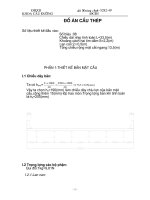
Application of this Part 1-2 is illustrated below. The prescriptive approach and the performance-based
approach are identified. The prescriptive approach uses nominal fires to generate thermal actions. The
performance-based approach, using fire safety engineering, refers to thermal actions based on physical
and chemical parameters.
For design according to this part, EN 1991-1-2 is required for the determination of thermal and
mechanical actions to the structure.
8
EN 1994-1-2:2005 (E)
Licensed Copy: x x, University of Glamorgan, Mon Apr 23 19:04:52 GMT+00:00 2007, Uncontrolled Copy, (c) BSI
Design Procedures
Prescriptive Rules
(Thermal Actions given by Nominal Fire)
Tabulated
Data
Analysis of
a Member
Analysis of Part
of the Structure
Analysis of
Entire Structure
Determination of
Mechanical Actions
and Boundary
conditions
Determination of
Mechanical Actions
and Boundary
conditions
Selection of
Mechanical
Actions
Simple Calculation
Models
Advanced
Calculation
Models
Simple Calculation
Models
(if available)
Advanced
Calculation
Models
Advanced
Calculation
Models
Performance-Based Code
(Physically based Thermal Actions)
Selection of Simple or
Advanced Fire Development
Models
Analysis of
a Member
Analysis of Part
of the Structure
Analysis of
Entire Structure
Determination of
Mechanical Actions
and Boundary
conditions
Determination of
Mechanical Actions
and Boundary
conditions
Selection of
Mechanical
Actions
Advanced
Calculation
Models
Advanced
Calculation
Models
Simple Calculation
Models
(if available)
Advanced
Calculation
Models
Figure 0.1: Alternative design procedures
Design aids
Apart from simple calculation models, EN 1994-1-2 gives design solutions in terms of tabulated data
(based on tests or advanced calculation models) which may be used within the specified limits of validity.
It is expected, that design aids based on the calculation models given in EN 1994-1-2, will be prepared by
interested external organizations.
The main text of EN 1994-1-2 together with informative Annexes A to I includes most of the principal
concepts and rules necessary for structural fire design of composite steel and concrete structures.
9
EN 1994-1-2:2005 (E)
Licensed Copy: x x, University of Glamorgan, Mon Apr 23 19:04:52 GMT+00:00 2007, Uncontrolled Copy, (c) BSI
National annex for EN 1994-1-2
This standard gives alternative procedures, values and recommendations for classes with notes
indicating where national choices may have to be made. Therefore the National Standard implementing
EN 1994-1-2 should have a National annex containing all Nationally Determined Parameters to be used
for the design of buildings to be constructed in the relevant country.
National choice is allowed in EN 1994-1-2 through clauses:
– 1.1(16)
– 2.1.3(2)
– 2.3(1)P
– 2.3(2)P
– 2.4.2(3)
– 3.3.2(9)
– 4.1(1)P
– 4.3.5.1(10)
10
EN 1994-1-2:2005 (E)
Licensed Copy: x x, University of Glamorgan, Mon Apr 23 19:04:52 GMT+00:00 2007, Uncontrolled Copy, (c) BSI
Section 1
1.1
General
Scope
(1) This Part 1-2 of EN 1994 deals with the design of composite steel and concrete structures for the
accidental situation of fire exposure and is intended to be used in conjunction with EN 1994-1-1 and
EN 1991-1-2. This Part 1-2 only identifies differences from, or supplements to, normal temperature
design.
(2) This Part 1-2 of EN 1994 deals only with passive methods of fire protection. Active methods are not
covered.
(3) This Part 1-2 of EN 1994 applies to composite steel and concrete structures that are required to fulfil
certain functions when exposed to fire, in terms of:
-
avoiding premature collapse of the structure (load bearing function);
-
limiting fire spread (flame, hot gases, excessive heat) beyond designated areas (separating function).
(4) This Part 1-2 of EN 1994 gives principles and application rules (see EN 1991-1-2) for designing
structures for specified requirements in respect of the aforementioned functions and the levels of
performance.
(5) This Part 1-2 of EN 1994 applies to structures, or parts of structures, that are within the scope of
EN 1994-1-1 and are designed accordingly. However, no rules are given for composite elements which
include prestressed concrete parts.
(6) For all composite cross-sections longitudinal shear connection between steel and concrete should be
in accordance with EN 1994-1-1 or be verified by tests (see also 4.3.4.1.5 and Annex I).
(7) Typical examples of concrete slabs with profiled steel sheets with or without reinforcing bars are given
in Figure 1.1.
Trapezoidal
profile
Re-entrant profile
Flat profile
Figure 1.1 Typical examples of concrete slabs with profiled steel sheets with or without
reinforcing bars
11
Licensed Copy: x x, University of Glamorgan, Mon Apr 23 19:04:52 GMT+00:00 2007, Uncontrolled Copy, (c) BSI
EN 1994-1-2:2005 (E)
(8) Typical examples of composite beams are given in Figures 1.2 to 1.5. The corresponding
constructional detailing is covered in section 5.
2
1
3
Key
1 – Shear connectors
2 – Flat concrete slab or composite slab with profiled steel sheeting
3 – Profiles with or without protection
Figure 1.2: Composite beam comprising steel beam with no concrete encasement
1
2
3
Key
1 – Optional
2 – Stirrups welded to web of profile
3 – Reinforcing bar
Figure 1.3: Steel beam with partial concrete encasement
1
1
Key
1 – Reinforcing bar
Figure 1.4: Steel beam partially encased in slab
2
Key
1 – Reinforcing bar
2 – Shear connectors
Figure 1.5: Composite beam comprising steel
beam with partial concrete encasement
(9) Typical examples of composite columns are given in Figures 1.6 to 1.8. The corresponding
constructional detailing is covered in section 5.
12
Licensed Copy: x x, University of Glamorgan, Mon Apr 23 19:04:52 GMT+00:00 2007, Uncontrolled Copy, (c) BSI
EN 1994-1-2:2005 (E)
1
Key
1 – Shear connectors welded to
web of profile
Figure 1.6:
Concrete encased profiles
Figure 1.7:
Partially encased profiles
Figure 1.8:
Concrete filled profiles
(10) Different shapes, like circular or octagonal cross-sections may also be used for columns. Where
appropriate, reinforcing bars may be replaced by steel sections.
(11) The fire resistance of these types of constructions may be increased by applying fire protection
materials.
NOTE:
The design principles and rules given in 4.2, 4.3 and 5 refer to steel surfaces directly exposed to the
fire, which are free of any fire protection material, unless explicitly specified otherwise.
(12)P The methods given in this Part 1-2 of EN 1994 are applicable to structural steel grades S235,
S275, S355, S420 and S460 of EN 10025, EN 10210-1 and EN 10219-1.
(13) For profiled steel sheeting, reference is made to section 3.5 of EN 1994-1-1.
(14) Reinforcing bars should be in accordance with EN 10080.
(15) Normal weight concrete, as defined in EN 1994-1-1, is applicable to the fire design of composite
structures. The use of lightweight concrete is permitted for composite slabs.
(16) This part of EN 1994 does not cover the design of composite structures with concrete strength
classes lower than C20/25 and LC20/22 and higher than C50/60 and LC50/55.
NOTE :
Information on Concrete Strength Classes higher than C50/60 is given in section 6 of EN 1992-1-2.
The use of these concrete strength classes may be specified in the National Annex.
(17) For materials not included herein, reference should be made to relevant CEN product standards or
European Technical Approval (ETA).
1.2
Normative references
(1)P This European Standard incorporates by dated or undated reference, provisions from other
publications. These normative references are cited at the appropriate places in the text and the
publications are listed hereafter. For dated references, subsequent amendments to or revisions of any of
these publications apply to this European Standard only when incorporated in it by amendment or
revision. For undated references the latest edition of the publication referred to applies (including
amendments).
EN 1365 -1
Fire resistance tests for loadbearing elements – Part 1: Walls
EN 1365 -2
Fire resistance tests for loadbearing elements – Part 2: Floors and roofs
EN 1365 -3
Fire resistance tests for loadbearing elements – Part 3: Beams
13
Licensed Copy: x x, University of Glamorgan, Mon Apr 23 19:04:52 GMT+00:00 2007, Uncontrolled Copy, (c) BSI
EN 1994-1-2:2005 (E)
EN 1365 -4
Fire resistance tests for loadbearing elements – Part 4: Columns
EN 10025-1
Hot-rolled products of structural steels - Part 1: General
conditions
EN 10025-2
Hot-rolled products of structural steels - Part 2: Technical delivery conditions for
non-alloy structural steels
EN 10025-3
Hot-rolled products of structural steels - Part 3: Technical delivery conditions for
normalized/normalized rolled weldable fine grain structural steels
EN 10025-4
Hot-rolled products of structural steels - Part 4: Technical delivery conditions for
thermomechanical rolled weldable fine grain structural steels
EN 10025-5
Hot-rolled products of structural steels - Part 5: Technical delivery conditions for
structural steels with improved atmospheric corrosion resistance
EN 10025-6
Hot-rolled products of structural steels - Part 6: Technical delivery conditions for
flat products of high yield strength structural steels in the quenched and
tempered condition
EN 10080
Steel for the reinforcement of concrete - Weldable reinforcing steel General
EN 10210-1
Hot finished structural hollow sections of non-alloy and fine grain structural steels
– Part 1 : Technical delivery conditions
EN 10219-1
Cold formed welded structural hollow sections of non-alloy and fine grain
structural steels – Part 1: Technical delivery conditions
ENV 13381-1
Test methods for determining the contribution to the fire resistance of structural
members – Part 1: Horizontal protective membranes
ENV 13381-2
Test methods for determining the contribution to the fire resistance of structural
members – Part 2: Vertical protective membranes
ENV 13381-3
Test methods for determining the contribution to the fire resistance of structural
members – Part 3: Applied protection to concrete members
ENV 13381-4
Test methods for determining the contribution to the fire resistance of structural
members – Part 4: Applied protection to steel members
ENV 13381-5
Test methods for determining the contribution to the fire resistance of structural
members – Part 5: Applied protection to concrete/profiled sheet composite
members
ENV 13381-6
Test methods for determining the contribution to the fire resistance of structural
members – Part 6: Applied protection to concrete filled hollow sheet columns
EN 1990
Eurocode: Basis of structural design
EN 1991 -1-1
Eurocode 1 : Actions on Structures – Part 1.1: General Actions - Densities, selfweight and imposed loads
EN 1991 -1-2
Eurocode 1 : Actions on Structures – Part 1.2: General Actions - Actions on
structures exposed to fire
14
technical
delivery
Licensed Copy: x x, University of Glamorgan, Mon Apr 23 19:04:52 GMT+00:00 2007, Uncontrolled Copy, (c) BSI
EN 1994-1-2:2005 (E)
EN 1991 -1-3
Eurocode 1 : Actions on Structures – Part 1.3: General Actions - Actions on
structures - Snow loads
EN 1991 -1-4
Eurocode 1 : Actions on Structures – Part 1.4: General Actions - Actions on
structures - Wind loads
EN 1992-1-1
Eurocode 2: Design of concrete structures - Part 1.1: General
rules and rules for buildings
EN 1992-1-2
Eurocode 2: Design of concrete structures - Part 1.2: Structural
fire design
EN 1993-1-1
Eurocode 3: Design of steel structures - Part 1.1: General rules and rules for
buildings
EN 1993-1-2
Eurocode 3: Design of steel structures - Part 1.2: Structural fire design
EN 1993-1-5
Eurocode 3: Design of steel structures - Part 1.5: Plated structural elements
EN 1994-1-1
Eurocode 4: Design of composite steel and concrete structures - Part 1.1:
General rules and rules for buildings"
1.3
Assumptions
(1)P Assumptions of EN 1990 and EN 1991-1-2 apply.
1.4
Distinction between Principles and Application Rules
(1) The rules given in EN 1990 clause 1.4 apply.
1.5
Definitions
(1)P The rules given in clauses 1.5 of EN 1990 and EN 1991-1-2 apply
(2)P The following terms are used in Part 1-2 of EN 1994 with the following meanings:
1.5.1 Special terms relating to design in general
1.5.1.1
axis distance
distance between the axis of the reinforcing bar and the nearest edge of concrete
1.5.1.2
part of structure
isolated part of an entire structure with appropriate support and boundary conditions
1.5.1.3
protected members
members for which measures are taken to reduce the temperature rise in the member due to fire
1.5.1.4
braced frame
a frame which has a sway resistance supplied by a bracing system which is sufficiently stiff for it to be
acceptably accurate to assume that all horizontal loads are resisted by the bracing system
15
EN 1994-1-2:2005 (E)
Licensed Copy: x x, University of Glamorgan, Mon Apr 23 19:04:52 GMT+00:00 2007, Uncontrolled Copy, (c) BSI
1.5.2 Terms relating to material and products properties
1.5.2.1
failure time of protection
duration of protection against direct fire exposure; that is the time when the fire protective claddings or
other protection fall off the composite member, or other elements aligned with that composite member fail
due to collapse, or the alignment with other elements is terminated due to excessive deformation of the
composite member
1.5.2.2
fire protection material
any material or combination of materials applied to a structural member for the purpose of increasing its
fire resistance
1.5.3 Terms relating to heat transfer analysis
1.5.3.1
section factor
for a steel member, the ratio between the exposed surface area and the volume of steel; for an enclosed
member, the ratio between the internal surface area of the exposed encasement and the volume of steel
1.5.4 Terms relating to mechanical behaviour analysis
1.5.4.1
critical temperature of structural steel
for a given load level, the temperature at which failure is expected to occur in a structural steel element
for a uniform temperature distribution
1.5.4.2
critical temperature of reinforcement
the temperature of the reinforcement at which failure in the element is expected to occur at a given load
level
1.5.4.3
effective cross section
cross section of the member in structural fire design used in the effective cross section method. It is
obtained by removing parts of the cross section with assumed zero strength and stiffness
1.5.4.4
maximum stress level
for a given temperature, the stress level at which the stress-strain relationship of steel is truncated to
provide a yield plateau
1.6
Symbols
(1)P For the purpose of this Part 1-2 of EN 1994, the following symbols apply
Latin upper case letters
A
cross-sectional area or concrete volume of the member per metre of member length
Aa,θ
cross-sectional area of the steel profile at the temperature θ
Ac,θ
cross-sectional area of the concrete at the temperature θ
Af
cross-sectional area of a steel flange
16
EN 1994-1-2:2005 (E)
Licensed Copy: x x, University of Glamorgan, Mon Apr 23 19:04:52 GMT+00:00 2007, Uncontrolled Copy, (c) BSI
Ai, Aj
elemental area of the cross section with a temperature θi or θj
or the exposed surface area of the part i of the steel cross-section per unit length
A/Lr
the rib geometry factor
Ai / Vi
section factor [m-1] of the part i of the steel cross-section (non-protected member)
Am
directly heated surface area of member per unit length
Am /V
section factor of structural member
Ap,i
area of the inner surface of the fire protection material per unit length of the part i of
the steel member
Ap,i / Vi
section factor [m-1] of the part i of the steel cross-section (with contour protection)
Ar
cross-sectional area of the stiffeners
Ar /Vr
section factor of stiffeners
As,θ
cross-sectional area of the reinforcing bars at the temperature θ
E
integrity criterion
E 30
or E 60,...a member complying with the integrity criterion for 30, or 60... minutes in
standard fire exposure
Ea
characteristic value for the modulus of elasticity of structural steel at 20°C
Ea,f
characteristic value for the modulus of elasticity of a profile steel flange
Ea,θ
characteristic value for the slope of the linear elastic range of the stress-strain
relationship of structural steel at elevated temperatures
Ea,θ,σ
tangent modulus of the stress-strain relationship of the steel profile at elevated
temperature θ and for stress σi,θ
Ec,sec,θ
characteristic value for the secant modulus of concrete in the fire situation, given by
fc,θ divided by εcu,θ
Ec0,θ
characteristic value for the tangent modulus at the origin of the stress-strain
relationship for concrete at elevated temperatures and for short term loading
Ec,θ,σ
tangent modulus of the stress-strain relationship of the concrete at elevated
temperature θ and for stress σi,θ
Ed
design effect of actions for normal temperature design
Efi,d
design effect of actions in the fire situation, supposed to be time independent
Efi,d,t
design effect of actions, including indirect fire actions and loads in the fire situation,
at time t
(EI)fi,c,z
flexural stiffness in the fire situation (related to the central axis Z of the composite
cross-section)
17
Licensed Copy: x x, University of Glamorgan, Mon Apr 23 19:04:52 GMT+00:00 2007, Uncontrolled Copy, (c) BSI
EN 1994-1-2:2005 (E)
(EI)fi,eff
effective flexural stiffness in the fire situation
(EI)fi,f,z
flexural stiffness of the two flanges of the steel profile in the fire situation (related to
the central axis Z of the composite cross-section)
(EI)fi,s,z
flexural stiffness of the reinforcing bars in the fire situation (related to the central axis
Z of the composite cross-section)
(EI)fi,eff,z
effective flexural stiffness (for bending around axis z) in the fire situation
(EI)fi,w,z
flexural stiffness of the web of the steel profile in the fire situation (related to the
central axis Z of the composite cross-section)
Ek
characteristic value of the modulus of elasticity
Es
modulus of elasticity of the reinforcing bars
Es,θ
characteristic value for the slope of the linear elastic range of the stress-strain
relationship of reinforcing steel at elevated temperatures
Es,θ,σ
tangent modulus of the stress-strain relationship of the reinforcing steel at elevated
temperature θ and for stress σi,θ
Fa
compressive force in the steel profile
F +, F -
total compressive force in the composite section in case of sagging or hogging
bending moments
Fc
compression force in the slab
Gk
characteristic value of a permanent action
HC
hydrocarbon fire exposure curve
I
thermal insulation criterion
Ii,θ
second moment of area, of the partially reduced part i of the cross-section for
bending around the weak or strong axis in the fire situation
I 30
or I 60,... a member complying with the thermal insulation criterion for 30, or 60...
minutes in standard fire exposure
L
system length of a column in the relevant storey
Lei
buckling length of a column in an internal storey
Let
buckling length of a column in the top storey
M
bending moment
Mfi,Rd+; Mfi,Rd -
design value of the sagging or hogging moment resistance in the fire situation
Mfi,t,Rd
design moment resistance in the fire situation at time t
N
number of shear connectors in one critical length,
18
EN 1994-1-2:2005 (E)
Licensed Copy: x x, University of Glamorgan, Mon Apr 23 19:04:52 GMT+00:00 2007, Uncontrolled Copy, (c) BSI
or axial load
Nequ
equivalent axial load
Nfi,cr
elastic critical load (≡ Euler buckling load) in the fire situation
Nfi,cr,z
elastic critical load (≡ Euler buckling load) around the axis Z in the fire situation
Nfi,pl,Rd
design value of the plastic resistance to axial compression of the total cross-section
in the fire situation
Nfi,Rd
design value of the resistance of a member in axial compression (≡ design axial
buckling load) and in the fire situation
Nfi,Rd,z
design value of the resistance of a member in axial compression, for bending around
the axis Z, in the fire situation
Nfi,Sd
design value of the axial load in the fire situation
NRd
axial buckling load at normal temperature
Ns
normal force in the hogging reinforcement (As . fsy)
PRd
design shear resistance of a headed stud automatically welded
Pfi,Rd
design shear resistance in the fire situation of a shear connector
Qk,1
characteristic value of the leading variable action 1
R
Load bearing criterion
R 30
or R 60, R90, R120, R180, R240... a member complying with the load bearing
criterion for 30, 60, 90, 120, 180 or 240 minutes in standard fire exposure
Rd
design resistance for normal temperature design
Rfi,d,t
design resistance in the fire situation, at time t
Rfi,y,Rd
design crushing resistance in the fire situation
T
tensile force
V
volume of the member per unit length
Vfi,pl,Rd
design value of the shear plastic resistance in the fire situation
Vfi,Sd
design value of the shear force in the fire situation
Vi
volume of the part i of the steel cross section per unit length [m3/m]
X
X (horizontal) axis
Xfi,d
design values of mechanical (strength and deformation) material properties in the
fire situation
19
Licensed Copy: x x, University of Glamorgan, Mon Apr 23 19:04:52 GMT+00:00 2007, Uncontrolled Copy, (c) BSI
EN 1994-1-2:2005 (E)
Xk
characteristic or nominal value of a strength or deformation property for normal
temperature design
Xk,θ
value of a material property in the fire situation, generally dependant on the material
temperature
Y
Y (vertical) axis
Z
Z (column) central axis of the composite cross-section
Latin lower case letters
aw
throat thickness of weld (connection between steel web and stirrups)
b
width of the steel section
b1
width of the bottom flange of the steel section
b2
width of the upper flange of the steel section
bc
depth of the composite column made of a totally encased section,
or width of concrete partially encased steel beams
bc,fi
width reduction of the encased concrete between the flanges in the fire situation
bc,fi,min
minimum value of the width reduction of the encased concrete between the flanges
in the fire situation
beff
effective width of the concrete slab
bfi
width reduction of upper flange in the fire situation
c
specific heat,
or buckling curve,
or concrete cover from edge of concrete to border of structural steel
ca
specific heat of steel
cc
specific heat of normal weight concrete
cp
specific heat of the fire protection material
d
diameter of the composite column made of concrete filled hollow section, or
diameter of the studs welded to the web of the steel profile
dp
thickness of the fire protection material
e
thickness of profile or hollow section
e1
thickness of the bottom flange of the steel profile
e2
thickness of the upper flange of the steel profile
ef
thickness of the flange of the steel profile
ew
thickness of the web of the steel profile
20
Licensed Copy: x x, University of Glamorgan, Mon Apr 23 19:04:52 GMT+00:00 2007, Uncontrolled Copy, (c) BSI
EN 1994-1-2:2005 (E)
ef
external fire exposure curve
fay,θ
maximum stress level or effective yield strength of structural steel in the fire situation
fay,θcr
strength of steel at critical temperature θcr
fap,θ ; fsp,θ
proportional limit of structural or reinforcing steel in the fire situation
fau,θ
ultimate tensile strength of structural steel or steel for stud
situation, allowing for strain-hardening
fay
characteristic or nominal value for the yield strength of structural steel at 20°C
fc
characteristic value of the compressive cylinder strength of concrete at 28 days and
at 20°C.
fc,j
characteristic strength of concrete part j at 20°C.
fc,θ
characteristic value for the compressive cylinder strength of concrete in the fire
situation at temperature θ°C.
fc,θn
residual compressive strength of concrete heated to a maximum temperature (with
n layers)
fc,θy
residual compressive strength of concrete heated to a maximum temperature
ffi,d
design strength property in the fire situation
fk
characteristic value of the material strength
fry, fsy
characteristic or nominal value for the yield strength of a reinforcing bar at 20°C
fsy,θ
maximum stress level or effective yield strength of reinforcing steel in the fire
situation
fy,i
nominal yield strength fy for the elemental area Ai taken as positive on the
compression side of the plastic neutral axis and negative on the tension side
h
depth or height of the steel section
h1
height of the concrete part of a composite slab above the decking
h2
height of the concrete part of a composite slab within the decking
h3
thickness of the screed situated on top of the concrete
hc
depth of the composite column made of a totally encased section,
or thickness of the concrete slab
heff
effective thickness of a composite slab
hfi
height reduction of the encased concrete between the flanges in the fire situation
connectors in the fire
•
h net
design value of the net heat flux per unit area
21