Thiết kế móng cọc theo mô hình chống giằng (design of pile caps)
Bạn đang xem bản rút gọn của tài liệu. Xem và tải ngay bản đầy đủ của tài liệu tại đây (168.02 KB, 12 trang )
ACI STRUCTURAL JOURNAL
TECHNICAL PAPER
Title no. 93-S41
Design of Deep Pile Caps by Strut-and-Tie Models
by Perry Adebar and Luke (Zongyu) Zhou
Comparisons with results from 48 pile cap tests demonstrate that the oneway shear design provisions of the present ACI Building Code are excessively conservative for deep pile caps, and that the traditional flexural
design procedures for beams and two-way slabs are unconservative for pile
caps. Flexural design can best be accomplished using a simple strut-andtie model, and test results demonstrate that the longitudinal reinforcement
should be concentrated over the piles as suggested by strut-and-tie models.
A simple shear design procedure is proposed in which maximum bearing
stress is considered the best indicator of “shear strength” for deep pile
caps. The maximum bearing stress that can be applied without causing
splitting of compression struts within pile caps depends on the amount of
confinement, as well as the aspect ratio (height-to- width) of compression
struts. The influence of confinement is more gradual than suggested by the
ACI Code bearing strength provisions.
Keywords: building codes; caps (supports); deep beams; footings; piles;
reinforced concrete; shear strength; structural design; strut-and-tie
mod els; tests.
The ACI Building Code procedure for the shear design of
footings supported on piles (pile caps) is the same sectional
approach used for footings supported on soil and for twoway slabs. The procedure involves determining the section
thickness that gives a concrete contribution Vc greater than
the shear force applied on the code- defined critical section.
While this approach is reasonable for slender footings supported on numerous piles, it is not appropriate for deep pile caps.
A change recently introduced in the ACI Building Code1
means that the critical section for one-way shear in deep pile
caps is now at the column face rather than d from the column face. This relatively small change in location of the
critical section has resulted in a very significant increase in
the required depth of many deep pile caps. The fact that a
small change in location of the critical section has such a
large consequence is a demonstration that a sectional approach is not appropriate in this case. It is also important to
note that the drastic increase in the ACI Code shear requirements for deep pile caps implies that either the present
method is overly conservative or that previously designed
deep pile caps may be unsafe.
As the ACI Code shear design procedures are not appropriate for deep pile caps (they were not developed for that
purpose), the CRSI Handbook2 suggests an alternate oneACI Structural Journal / July-August 1996
way shear design procedure when the center of the nearest
pile is within d from the column face, and an alternate twoway shear design procedure when the center of the nearest
pile is within d/2 from the column face. The CRSI Handbook
alternate procedures involve a critical section along the column face for both one-way and two-way shear, as well as
modified expressions for the concrete contribution.
Another approach for deep pile caps is to use strut-and-tie
models3,4,5 that consider the complete flow of forces rather
than the forces at any one particular section. The internal
load path in cracked reinforced concrete is approximated by
an idealized truss, where zones of concrete with primarily
unidirectional compressive stresses are modeled by compression struts, tension ties are used to model the principal
reinforcement, and the areas of concrete where strut and ties
meet (referred to as nodal zones) are analogous to joints of a
truss. While the concept of using a truss analogy for the flexural design of deep pile caps (i.e., determining the required
amount of longitudinal reinforcement) is well known,6,7,8 a
sectional approach has invariably been used for the shear design of pile caps.
Unlike traditional design procedures, strut-and-tie models
do not separate flexural and shear design; however, it may be
said that the “shear design” of deep members using strutand-tie models involves limiting the concrete stresses to insure that the tension tie reinforcement yields prior to a concrete shear failure. If sufficient distributed reinforcement is
provided to insure crack control, thereby allowing internal
redistribution of stresses after cracking, the compressive
stresses in the concrete struts should be limited depending on
the biaxial strains.4 On the other hand, if little or no reinforcement is provided for crack control, the concrete tensile
stresses should be limited to avoid diagonal cracking of compression struts.5 In pile caps it is usually not practical to provide sufficient distributed (horizontal and vertical)
ACI Structural Journal, V. 93, No. 4, July-August 1996.
Received Dec. 22, 1993, and reviewed under Institute publication policies. Copyright 1996, American Concrete Institute. All rights reserved, including the making
of copies unless permission is obtained from the copyright proprietors. Pertinent discussion will be published in the May-June 1997 ACI Structural Journal if received by
Jan. 1, 1997.
1
ACI member Perry Adebar is an assistant professor in the Department of Civil Engineering at the University of British Columbia, Vancouver, Canada. He is Secretary of
Joint ACI-ASCE Committee 441, Reinforced Concrete Columns; and is a member of
Joint ACI-ASCE Committee 445, Shear and Torsion; and ACI Committee 341, Earthquake-Resistant Concrete Bridges.
Luke (Zongyu) Zhou is a structural designer with Jones, Kwong, Kishi in North Vancouver, Canada. He holds engineering degrees from Tongji University and a doctorate
in structural engineering from the University of British Columbia.
reinforcement to insure crack control; therefore, diagonal
cracking of the compression struts should be avoided. Adebar and Zhou9 have recently developed bearing stress limits
to avoid transverse splitting in concrete compression struts
confined by plain concrete, similar to the situation that occurs in pile caps. Utilizing these concrete stress limits, strutand-tie models can be used for both “flexural design” and
“shear design” of deep pile caps.
In this paper the methods commonly used in North America for the design of deep pile caps are briefly reviewed. This
includes the ACI Building Code with and without the recent
modifications, as well as the method suggested in the CRSI
Handbook. A shear design procedure for deep pile caps
based on the strut-and-tie model concept is presented, and results from 48 deep pile cap tests are reviewed and compared
with predictions from the different design methods.
RESEARCH SIGNIFICANCE
Deep pile caps are important structural elements that are
not adequately covered by the ACI Building Code. Many
pile caps are designed by design aids with rule-of-thumb
procedures and what are hoped to be conservative allowable stresses, but considerable disparity exists between the
various procedures.
The information presented in this paper should prove useful to the organizations who publish design aids for deep pile
caps and practicing engineers who must design appropriate
pile cap designs.
DESIGN METHODS
ACI Building Code
The ACI Building Code (ACI-318) does not contain any
provisions specifically for deep pile caps. Thus, designs are
based on the procedure for slender footings that can be divided into three separate steps: 1) shear design, which involves
calculating the minimum pile cap depth so that the concrete
contribution to shear resistance is greater than the shear applied on the code-defined critical sections for shear; 2) flexural design, in which the usual assumptions for reinforced
concrete beams are used to determine the required amount of
longitudinal reinforcement at the critical section for flexure;
and 3) a check of the bearing stress at the base of the column
and at the top of the piles.
The special provisions for the shear design of slabs and
footings (Section 11.12) requires that designers consider
both one-way and two-way shear. In the 1977 and earlier editions of the ACI Code, 10 the special provisions for slabs and
footings specifically stated that the critical section for oneway shear was located at a distance d from the face of the
concentrated load or reaction area. In addition, Section 11.1 of
2
the ACI Code stated that sections located less than a distance
d from the face of support may be designed for the same
shear as that computed at a distance d. The commentary to
Section 11.1 warned that if the shear at sections between the
support and a distance d differed radically from the shear at
distance d, as occurs when a concentrated load is located
close to the support, the critical section should be taken at the
face of the support. Designers of pile caps could ignore this
warning, however, since the specific statement in the code
for slab and footings superseded the more general statement
made in the commentary. In addition, a number of technical
reports (e.g., Reference 11) described how the shear strength
of deep members is much greater than the shear strength of
slender members.
In the 1983 and subsequent editions of the ACI Code, the
statement about the location of critical section for one-way
shear was removed from the special shear provisions for
slabs and footings, and the general statement about the critical section being at the face of the support when a concentrated load occurs within d from the support was moved from
the commentary to the code. In addition, the commentary
was modified to include a footing supported on piles as an
example of when the critical section is commonly at the face
of the support. The result is that designers of deep pile caps
now have no choice but to take the critical section for oneway shear at the face of the column.
The ACI Building Code procedures for two-way shear
have not been modified recently. The critical section remains
at d/2 from the perimeter of the column regardless whether
there is a concentrated load applied within the critical section. Section 15.5.3 states that any pile located inside the critical section is considered to produce no shear on the critical
section and describes how to calculate the contribution from
any pile that intercepts the critical section. The commentary
on Section 15.5.3 contains a statement (since 1977) that
when piles are located within the critical section, analysis for
shear in deep flexural members, in accordance with Section
11.8, needs to be considered. Unfortunately, Section 11.8 of
the ACI Code addresses only one-way shear in deep members, where the critical section is taken midway between the
concentrated load and the support and the concrete contribution is increased due to deep beam action.
The ACI Building Code specifies that the critical section
for moment in footings is at the face of concrete columns.
The quantity of longitudinal reinforcement required at this
critical section is determined by the usual procedures for reinforced concrete members, assuming plane sections remain
plane and assuming that there is uniform flexural compression stresses across the entire width of the member. The designer is told to distribute the required longitudinal
reinforcement uniformly across the footing (except that the
short-direction reinforcement of rectangular footings must
be somewhat more concentrated near the center).
According to the ACI Code, the maximum bearing
strength of concrete is 0.85 fc′, except when the supporting
surface area A 2 is wider on all sides than the loaded area A1 ,
the bearing strength is multiplied by A 2 ⁄ A 1 but not more
than 2.
ACI Structural Journal / July-August 1996
CRSI Handbook
The CRSI Handbook2 makes use of the general design
procedures in the ACI Building Code for the design of pile
caps, with the exception of the shear design procedures for
deep pile caps. When the center of the nearest pile is within
d from the column face, the CRSI Handbook suggests that
the one-way shear capacity should be investigated at the face
of the column (similar to recent ACI Codes), but suggests
that the concrete contribution should be significantly increased to account for deep beam action. The suggested relationship for one-way shear is
d
V c C R S I = ----Vc ACI ≤ 10 f c′ b d
w
(a)
(b)
(1)
(c)
where w is the distance from the center of the nearest pile to
the face of the column. The CRSI Handbook suggests that to
include the effect of M/Vd for several piles at varying spans,
the more complex ACI Code expression for Vc [Eq. (11-6)]
should be used.
When the center of the nearest pile is within d/2, the CRSI
Handbook suggests that the two-way shear capacity should
also be investigated at the perimeter of the column face (this
is different than the ACI code), and again, the concrete contribution should be increased to account for deep (two-way
shear) action. The suggested relationship for two-way shear is
Vc
CRSI
d
d
= ------- 1 + -- 4 fc ′b o d ≤ 32 fc ′b o d
2w
c
(e)
(2)
where b o equals 4 × c for a square column of dimension c. As
the critical section is at the perimeter of the column, the
CRSI two-way shear strength equation is much more sensitive to the dimensions of the column compared to the ACI
approach, where the critical section is at d/2 from the column
perimeter [bo equals 4 × (c + d)]. The term (1 + d/c) in the
CRSI equation is a factor that compensates for this difference.
Strut-and-tie model
The influence of a concentrated load within d from the
face of the support of a member subjected to one-way shear
is summarized in Fig. 1. The sectional shear force in such a
member is very different depending on which side of the concentrated load the “critical section” is located on [see Fig. 1(b)].
The truss model shown in Fig. 1(d) indicates that the concentrated load is transmitted directly to the support by a compression strut. No stirrups are required to resist the “shear”
created by the concentrated load [see Fig. 1(f)]. The concentrated load does, however, increase the diagonal compression stresses in the concrete immediately above the support
[see Fig. 1(e)], as well as the required tension force in the
longitudinal reinforcement at the face of the support [see Fig.
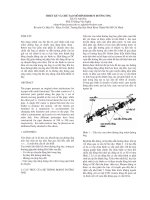
1(g)]. Fig. 2 depicts a simple three-dimensional strut-and-tie
model for a four-pile cap. The concentrated column load is
transmitted directly to the support by inclined compression
struts. Horizontal tension ties (longitudinal reinforcement)
are required to prevent the piles from being spread apart.
The “shear design” of a deep pile cap using a strut-and-tie
model involves limiting the concrete stresses in compression
ACI Structural Journal / July-August 1996
(d)
(f)
(g)
Fig. 1—Truss model for simply supported beam with concentrated load close to support: (a) geometry and loading;
(b) sectional shear forces; (c) sectional bending moments;
(d) truss model; (e) discontinuous stress field; (f) required
stirrup resistance per unit length of beam; (g) required longitudinal reinforcement (adapted from Marti3 )
struts and nodal zones to insure that the tension tie (longitudinal reinforcement) yields prior to any significant diagonal
cracking in the plain concrete compression struts. Schlaich et al.5
suggest that the concrete stresses within an entire disturbed
region can be considered safe if the maximum bearing stress
in all nodal zones is below a certain limit. Based on an analytical and experimental study of compression struts confined by plain concrete,9 it is proposed that the maximum
bearing stresses in nodal zones of deep pile caps be limited to
fb ≤ 0.6f c ′ + αβ72 fc ′
(3a)
1
α = -- ( A 2 ⁄ A 1 – 1 ) ≤ 1.0
3
(3b)
3
Fig.2—Simple three-dimensional truss model for four-pile cap
1 h
β = -- ----s – 1 ≤ 1.0
3 bs
(3c)
where f c′ and fb have units of psi. If MPa units are used, the
72 in Eq. (3a) should be replaced by 6. The parameter β accounts for confinement of the compression strut. The ratio
A2 /A1 in Eq. (3b) is identical to that used in the ACI Code
to calculate bearing strength. The parameter β accounts for
the geometry of the compression strut, where the ratio h s /b s
is the aspect ratio (height-to-width) of the compression
strut. To calculate the maximum bearing stress for the nodal
zone below a column, where two or more compression
struts meet, the aspect ratio of the compression strut can be
approximated as
h
----s ≈ 2------d
bs c
(4)
where d is the effective depth of the pile cap and c is the dimension of a square column. For a round column, the diameter may be used in place of c. To calculate the maximum
bearing stress for a nodal zone above a pile, where only one
compression strut is anchored, the aspect ratio of the compression strut can be approximated as
hs d
---- ≈ ----bs dp
(5)
where d p is the diameter of a round pile. Note that the ratio
h s/b s should not be taken less than 1 (i.e., β ≥ 0).
4
The lower bearing stress limit of 0.6 fc′ in Eq. (3) is appropriate if there is no confinement (A2 /A1 ≈ 1), regardless of the
height of the compression strut, as well as when the compression strut is short (h s /bs ≈ 1), regardless of the amount of confinement. The upper limit of Eq. (3) results in similar
maximum bearing strengths as the ACI Code.
The proposed strut-and-tie model approach is intended for
the design of deep pile caps, not slender pile caps. As it is
not always obvious whether a pile cap is slender or deep, and
some pile caps may be somewhere in between, a general
shear design procedure for pile caps can be accomplished by
the following. First, choose the initial pile cap depth using
the traditional ACI Code one-way and two-way shear design
procedures. In the case of one-way shear, the critical section
should be taken at d from the column face, and any pile force
within the critical section should be ignored (i.e., the ACI
procedure prior to 1983). Second, the nodal zone bearing
stresses should be checked using Eq. (3). If necessary, the
pile cap depth may be increased (β increased), or the pile cap
dimensions may be increased to increase the confinement of
the nodal zones (α increased), or else the bearing stresses
may need to be reduced by increasing the column or pile dimensions. Thus, the shear strength of slender pile caps will
be limited by the traditional sectional shear design procedures, while the shear strength of deep pile caps will be limited by the nodal zone bearing stress limits.
Comparison of design methods
To compare the one-way shear design procedures, Fig. 3
summarizes the relationship between the maximum column
load and the width b and depth d of a two-pile cap. When the
width of the pile cap is the same as the column width (b = c),
the pile cap is essentially a deep beam [see Fig. 3(b)]. When
the width of the pile cap is increased, larger shear forces can
be resisted by the increased concrete area at the critical section, and the maximum bearing stress (and hence, maximum
column load) is larger as a result of increased confinement
[see Fig. 3(c) and (d)].
Three different ACI Code predictions for one-way shear
are given in Fig. 3. The least conservative prediction, entitled
“ACI ‘77,” is what designers of pile caps could have used
prior to the 1983 edition of the ACI Building Code (any pile
within d of the column face is assumed to produce no shear
on the critical section); the “ACI ‘83” procedure is what designers must use since the 1983 edition of the ACI Code
(critical section at the column face). This method gives very
conservative predictions. The procedure from Section 11.8
for deep flexural members, “ACI [11.8],” gives an intermediate result. The CRSI Handbook method, in which the critical section is also at the face of the column, is much less
conservative than “ACI ‘83” due to an enhanced concrete
contribution, but it's more conservative than when the critical section is taken at d from the column face (“ACI ‘77”).
All methods predict that when the pile cap is very deep, the
maximum column load is limited by bearing strength (indicated by the horizontal lines in Fig. 3). When the pile cap is
twice as wide as the column (b = 2c), the ACI Code predicts
that confinement is sufficient so that the bearing strength has
reached the upper limit of 2 × 0.85 fc′ = 1.7 fc ′. Results from
numerous bearing strength tests and the procedure proposed
ACI Structural Journal / July-August 1996
(a)
(a)
(b)
(b)
(c)
(d)
Fig. 3—Comparison of one-way shear design methods for
two-pile caps with fc ′ = 25 MPa: (a) plan view of pile cap; (b)
to (d) influence of pile cap depth on column load for various
pile cap widths (1 in. = 25.4 mm; 1 kip = 4.45 kN)
by Hawkins12 (which is the origin of the ACI Code procedure) indicate that the increase in bearing strength due to
confinement is more gradual than suggested by the ACI
ACI Structural Journal / July-August 1996
Fig. 4—Comparison of two-way shear design methods for
typical four-pile cap with fc′ = 25 MPa: (a) plan view of pile
cap; (b) influence of pile cap depth on column load (1 in. =
25.4 mm; 1 kip = 4.45 kN)
Code. That is, when b = 2c the confinement may not be sufficient to support a column bearing stress of 1.7 fc ′ (a detailed
discussion of this issue was recently presented by the
authors9 ).
Fig. 4 compares the influence of pile cap depth on twoway shear strength predictions for a typical four-pile cap. Although the CRSI Handbook expression gives a considerably
larger concrete contribution for deep pile caps than the ACI
Code, the maximum column load is always smaller than the
ACI Code method. This is because in the ACI Code method,
the critical section is at d/2 from the column face and any pile
that intercepts the critical section is assumed to transmit part
of the load directly to the column. For example, if a pile is
centered on the critical section, only half of the pile reaction
must be resisted by the critical section according to the ACI
Code method. It is interesting to note that as the CRSI Handbook method suggests that the ACI Code procedures be used
until the center of the nearest pile is at d/2 from the column
face, there is an abrupt reduction in maximum column load
at that point (d = 22 in. in Fig. 4). This problem can be corrected by applying the CRSI Handbook procedure when the
5
face of the pile is within d/2 of the column face so that none
of the pile shear bypasses the critical section; the result is
shown by the dashed line in Fig. 4.
The proposed method, which combines the “ACI ‘77” procedure for pile caps with smaller depths (slender pile caps)
with the more conservative bearing stress limit in Eq. (3)
gives a very reasonable result. Note that for the particular
example shown in Fig. 4, the pile bearing stress is slightly
more critical than column bearing stress. That is, according
to the proposed method, the confinement around the pile is
not sufficient to reach the maximum bearing stress limit.
EXPERIMENTAL RESULTS
The first results from tests on pile caps were reported by
Hobbs and Stein13 who tested numerous small-scale models
of two-pile caps. In all cases, the simulated column and piles
were the same width as the “pile cap,” so the models were
really wide deep beams. The models had various amounts of
either straight or curved nondeformed reinforcing bars that
were anchored by a number of different methods. Shear failure occurred when a diagonal crack formed between the column and a pile.
Deutsch and Walker14 tested four full-scale two-pile cap
specimens. The objective of the tests was to investigate the
influence of pile cap depth and the amount of reinforcing
steel. Specimens were stronger than anticipated, and two of
the specimens did not fail. All pile caps behaved similarly
with one main vertical (flexural) crack forming at midspan.
Blévot and Frémy7 tested two series of pile caps. The first
series consisted of 94 models at about half-scale, while the
second series consisted of 22 approximately full-scale specimens (eight four-pile caps, eight three-pile caps, and six
two-pile caps). The main objective of the tests was to determine the influence of pile cap depth and longitudinal reinforcement layout. The longitudinal reinforcement was either
concentrated over the piles, as suggested by a truss model, or
distributed in a uniform orthogonal grid, as required by the
ACI Code.
Bunching the longitudinal reinforcement resulted in higher
capacities (for a given quantity of steel), even though some
parts of the specimens had poor crack control. Distributing
an equal amount of reinforcement in a uniform grid resulted
in the four-pile caps being 20 percent weaker and the threepile caps being 50 percent weaker. The capacities were not
significantly influenced by whether the bunched reinforcement was provided around the perimeter of the pile cap or diagonally across the pile cap; however, the best crack control
under service loads occurred when a combination of the two
was used.
Clarke 8 tested 15 four-pile caps, all approximately halfscale. The longitudinal reinforcement layout and anchorage
were the parameters studied. Similar to Blévot and Frémy,
the reinforcement was either bunched over the piles or distributed in a uniform grid. In the study, “nominal anchorage”
involved extending the longitudinal reinforcement just beyond the piles, while “full anchorage” meant providing a 90deg hook and extending the longitudinal reinforcement to the
top of the pile cap.
The behavior of all pile caps was similar. Vertical cracks
formed near the center of the pile cap sides, extending to near
6
the top of the pile caps. Prior to failure, the pile caps had usually split into four separate pieces hinged below the column
base. According to the author, most specimens failed in
“shear” after the longitudinal reinforcement yielded. The author also classified the failure modes as either one-way
(beam) shear or two-way (punching) shear, depending on the
appearance of the failed specimen. Bunching the reinforcement over the piles resulted in a 14 percent increase in capacity compared to spreading the reinforcement uniformly. The
so-called “full anchorage” resulted in approximately a 30
percent increase in capacity.
Sabnis and Gogate 15 tested nine very small (1 /5 ) scale
models of four-pile caps to study how the quantity of uniformly distributed longitudinal reinforcement influences the
shear capacity of deep pile caps. Similar to Clarke,8 the longitudinal reinforcement was hooked and extended to the top
surface. The tests showed that varying the reinforcement ratio
between 0.0014 and 0.012 had little influence on the shear
capacities of the models; however, no details were given
about how artificial restraint was eliminated at the base of
the simulated piles.
Adebar, Kuchma, and Collins16 tested six full-scale pile
caps (five four-pile caps and one six-pile cap). The largest
specimen weighed more than 7 ton (6.4 tonne). All pile caps
were statically indeterminate (piles in four-pile caps were arranged in a diamond shape), and the actual pile loads were
measured throughout the test. Sliding bearings were used under the pseudo-piles to simulate the lateral flexibility of piles.
External and internal strain measurements taken during the
tests demonstrated that the behavior of pile caps is very different from two-way slabs. Plane sections do not remain
plane, and strut action is the predominant mechanism of shear
resistance. Deep pile caps deform very little before failure
and thus, have virtually no ability to redistribute pile loads.
Strain gages in two of the specimens indicated that the longitudinal reinforcement had definitely yielded prior to failure; however, the failure mode still looked very much like a
“shear failure” because the plain concrete in the pile caps had
very little ductility. The authors believed that true shear failures (prior to steel yielding) were a result of compression
struts splitting longitudinally. Depending on the geometry of
the pile cap, the final failure mechanism resembled either a
one-way or two-way shear failure. The maximum bearing
stress in specimens that failed in shear varied from 1.13 to
1.27 fc ′.
COMPARATIVE STUDY
Table 1 summarizes the properties of 48 pile cap specimens that are used in the comparative study. Specimens not
considered include the small wide-beam models tested by
Hobbs and Stein, the small-scale specimens (first series)
tested by Blévot and Frémy, and the two specimens tested by
Deutsch and Walker that did not fail.
Table 2 summarizes the details of the ACI Code and CRSI
Handbook predictions. In the case of one-way shear, three
different predictions are given from the ACI Building Code:
1) the 1977 edition of the ACI Building Code (critical section at d from the column face); 2) the 1983 ACI Building
Code (critical section at the column face); and 3) the special
provisions for deep flexural members (Section 11.8 of the
ACI Structural Journal / July-August 1996
Table 1—Summary of pile cap test results
Specimen
No. of
piles
d, mm
Column size,
mm
fc′, MPa
Reinforcement
layout
Failure load,
kN
2N1
2
495
350 square
2N1b
2
498
350 square
350 square
23.1
Bunched
2059
350 square
43.2
Bunched
2N2
2
703
3187
350 square
350 square
27.3
Bunched
2N2b
2
2942
698
350 square
350 square
44.6
Bunched
2N3
5100
2
894
350 square
350 square
32.1
Bunched
4413
2N3b
2
892
350 square
350 square
46.1
Bunched
5884
3N1
3
447
450 square
350 square
44.7
Bunched
4119
3N1b
3
486
450 square
350 square
44.5
Bunched
4904
3N3
3
702
450 square
350 square
45.4
Bunched
6080
3N3b
3
736
450 square
350 square
40.1
Bunched
6669
4N1
4
674
500 square
350 square
36.5
Bunched and grid
6865
4N1b
4
681
500 square
350 square
40.0
Bunched and grid
6571
4N2
4
660
500 square
350 square
36.4
Bunched
6453
4N2b
4
670
500 square
350 square
33.5
Bunched
7247
4N3
4
925
500 square
350 square
33.5
Bunched and grid
6375
4N3b
4
931
500 square
350 square
48.3
Bunched and grid
8826
4N4
4
920
500 square
350 square
34.7
Bunched
7385
4N4b
4
926
500 square
350 square
41.5
Bunched
8581
Pile size, mm
Blévot and Frémy7
Deutsch and
Walker 14
3
2
533
165 square
254 2
23.8
Bunched
596
4
2
373
165 square
254 2
23.6
Bunched
289
8
Clarke
A1
4
400
200 square
200 round
20.9
Grid
1110
A2
4
400
200 square
200 round
27.5
Bunched
1420
A3
4
400
200 square
200 round
31.1
Bunched
1340
A4
4
400
200 square
200 round
20.9
Grid
1230
A5
4
400
200 square
200 round
26.9
Bunched
1400
A6
4
400
200 square
200 round
26.0
Bunched
1230
A7
4
400
200 square
200 round
24.2
Grid
1640
A8
4
400
200 square
200 round
27.5
Bunched
1510
A9
4
400
200 square
200 round
26.8
Grid
1450
A10
4
400
200 square
200 round
18.2
Grid
1520
A11
4
400
200 square
200 round
17.4
Grid
1640
A12
4
400
200 square
200 round
25.3
Grid
1640
B1
4
400
200 square
200 round
26.9
Grid
2080
B3
4
400
200 square
200 round
36.3
Grid
1770
Sabnis and Gogate15
SS1
4
111
76 round
76 round
31.3
Grid
250
SS2
4
112
76 round
76 round
31.3
Grid
245
SS3
4
111
76 round
76 round
31.3
Grid
248
SS4
4
112
76 round
76 round
31.3
Grid
226
SS5
4
109
76 round
76 round
41.0
Grid
264
SS6
4
109
76 round
76 round
41.0
Grid
280
SG2
4
117
76 round
76 round
17.9
Grid
173
SG3
4
117
76 round
76 round
17.9
Grid
177
Adebar, Kuchma, and Collins16
A
4
445
300 square
200 round
24.8
Grid
1781
B
4
397
300 square
200 round
24.8
Bunched
2189
C
6
395
300 square
200 round
27.1
Bunched
2892
D
4
390
300 square
200 round
30.3
Bunched
3222
E
4
410
300 square
200 round
41.1
Bunched and grid
4709
F
4
390
300 square
200 round
30.3
Bunched
3026
ACI Structural Journal / July-August 1996
7
Table 2—Summary of ACI Building Code and CRSI Handbook predictions
Bearing
One-way shear
Two-way shear
ACI
Column
Specimen
Flexure
Column
Pile
1977
1983
(11.8)
CRSI
ACI
CRSI
Pile
2N1
2197
2749
5498
1049*
314
951
775
‡
‡
‡
2N1b
3756
5141
10,282
1442*
432
1295
902
‡
‡
‡
2N2
3432
3249
6498
†
490
1461
2432
‡
‡
‡
2N2b
5551
5308
10,616
†
618
1844
2628
‡
‡
‡
2N3
5413
3820
7640
†
677
2020
3364
‡
‡
‡
2N3b
7257
5487
10,974
†
804
3364
4021
‡
‡
‡
3N1
3825
15,388
23,877
2128*
1589*
4492
2020
3717*
6551
†
3N1b
5286
15,319
23,770
2697*
1716*
4737
2638
4394*
8061
†
3N3
6129
15,629
24,251
†
2511*
7493
9317
†
20,918
†
3N3b
7983
13,804
21,420
†
2471*
7385
9876
†
22,252
†
4N1
7924
15,513
25,996
†
2824
7257
11,866
11,852*
§
†
4N1b
8159
17,000
28,489
†
2766
7689
11,965
12,749*
§
†
4N2
7542
15,470
25,925
†
2373
7139
11,307
11,003*
§
†
4N2b
8552
14,238
23,859
†
2314
6953
10,670
11,102*
§
†
4N3
8277
14,238
23,859
†
3609
9650
16,083
59,607*
13,220
†
4N3b
10,807
20,528
34,400
†
4080
11,239
19,320
71,621*
16,309
†
4N4
9866
14,748
24,714
†
3236
9709
16,182
54,998*
13,426
†
4N4b
10,866
17,638
29,557
†
3560
10,435
17,819
63,746*
14,937
†
No. 3
512
1102
3915
†
343
925
560
‡
‡
‡
No. 4
271
1092
3883
†
231
503
§
‡
‡
‡
A1
1258
1421
3907
†
604
1646
2718
2916*
1458
1996
A2
1266
1870
5140
†
684
1847
3078
3344*
1672
2288
A3
1256
2115
5813
†
722
1934
3250
3558*
1778
2434
A4
1258
1421
3907
†
604
1646
2718
2916*
1458
1996
A5
1265
1829
5028
†
678
1830
3052
3308*
1654
2263
A6
1252
1768
4860
†
664
1791
2988
3252*
1626
2225
A7
1262
1646
4524
†
644
1750
2898
3138*
1569
2148
A8
1266
1870
5140
†
684
1847
3078
3345*
1672
2288
A9
1264
1822
5010
†
676
1828
3042
3302*
1651
2260
A10
1252
1238
3402
†
566
1554
2548
2722*
1360
1860
A11
1252
1183
3253
†
556
1526
2502
2660*
1330
1820
A12
1262
1720
4729
†
658
1784
2962
3208*
1604
2196
B1
2022
1829
5028
†
578
2066*
2584
†
3308
†
B3
1528
2468
6785
†
636
2338*
3002
†
3843
†
SS1
133
241
806
†
69
186
256
122
§
228
SS2
116
241
806
†
68
178
252
122
§
228
SS3
194
241
806
†
69
181
251
121
§
226
SS4
158
241
806
†
71
192
262
122
§
228
SS5
317
316
1056
†
84
229
287
134
§
251
SS6
455
316
1056
†
89
229
305
134
§
251
SG2
302
138
461
†
65
164
254
101
§
185
SG3
628
138
461
†
85
164
329
101
§
185
A
2256
3794
5298
3246
2397
6056
6349
2309*
§
6247
B
2790
3794
5298
3411
2085
5308
4269
1839
§
2762
C
4009
4146
8684
6300
1820
4938
3740
1899
§
2990
D
5646
4636
6473
3773
2431
6348
4724
1968
§
3106
E
7428
6288
8780
4475
3076
8141
7058
2475
§
3970
F
5324
3083
6473
1604
573
1739
1619
‡
‡
‡
*Increased capacity since piles partially within critical section.
†Infinite capacity since piles totally within critical section.
‡Procedure not applicable.
§CRSI prediction not applicable (use ACI).
ACI Code). Table 3 presents the ratio of measured pile cap
capacity to predicted capacity for the three ACI Code predictions, as well as the CRSI Handbook prediction. The predicted
failure mode and reported failure mode are also given. It is
8
interesting to note that many pile caps predicted to fail in
flexure were reported to have failed in shear. As previously
mentioned, the likely reason for this is that pile caps are large
blocks of plain concrete that do not have the ductility to unACI Structural Journal / July-August 1996
Table 3—Comparison of ACI Code and CRSI
Handbook predictions: ratio of measured capacity
to predicted capacity and failure mode*
Name
2N1
2N1b
ACI ‘77
1.96 s1
ACI ‘83
6.56 s 1
ACI (11.8)
2.17 s 1
CRSI
2.66 s1
Table 4—Comparison of proposed strut-and-tie
model predicitons with experimental results
Predicted
Reported
failure
mode
Name
Flexure
Shear
Experimental
Experimental
Predicted
2N1
2127
1049a
2059
1.96 s
s
2N1b
3567
1442a
3187
2.21 s
2N2
3107
2156
2942
1.36 s
2N2b
5047
3470
5100
1.47 s
2N3
4831
2560
4413
1.72 s
2N3b
6439
3623
5884
1.62 s
3N1
3254
2128a
4119
1.94 s
2.21 s1
7.38 s 1
2.46 s 1
3.53 s1
s
2N2
0.91 b c
6.00 s 1
2.01 s 1
1.21 s1
s
2N2b
0.96 b c
8.25 s 1
2.77 s 1
1.94 s1
s
2N3
1.16 b c
6.52 s 1
2.18 s 1
1.31 s1
s
2N3b
1.07 b c
7.32 s 1
1.75 s 1
1.46 s1
s
3N1b
4528
2697a
4904
1.82 s
3N1
1.94 s1
2.59 s 1
1.11 s 2
2.04 s1
s
3N3
5067
7493
6080
1.20 f
3N1b
1.82 s1
2.86 s 1
1.04 s 1
1.86 s1
s
3N3b
6762
6885
6669
0.99 f
3N3
0.99 f
2.42 s 1
0.99 f
0.99 f
s
4N1
6037
9050
6865
1.14 f
3N3b
0.84 f
2.70 s 1
0.90 s 1
0.84 f
s
4N1b
6174
9826
6571
1.06 f
4N1
0.87 f
2.43 s 1
0.95 s 1
0.87 f
s
4N2
5929
8877
6453
1.09 f
4N1b
0.81 f
2.38 s 1
0.85 s 1
0.81 f
s
4N2b
6507
8377
7247
1.11 f
s
4N3
6203
10,600
6375
1.03 f
s
4N3b
7007
14,050
8826
1.26 f
4N4
7409
10,900
7385
1.00 f
4N4b
8144
12,450
8581
1.05 f
4N2
4N2b
4N3
0.86 f
0.85 f
0.77 f
2.72 s 1
3.13 s 1
0.90 s 1
1.04 s 1
1.77 s 1
0.77 f
0.86 f
0.85 f
0.77 f
s
4N3b
0.82 f
2.16 s 1
0.82 f
0.82 f
s
4N4
0.75 f
2.28 s 1
0.76 s 1
0.75 f
s
4N4b
0.79 f
2.41 s 1
0.82 s 1
0.79 f
s
No. 3
1.16 f
1.74 s 1
1.16 f
1.16 f
s
No. 4
1.07 f
1.25 s 1
1.07 f
1.07 f
A1
0.88 f
1.84 s 1
0.88 f
A2
1.12 f
2.08 s 1
A3
1.07 f
A4
0.98 f
A5
A6
A7
A8
1.11 f
0.98 f
1.30 f
1.19 f
No. 3
480
732
596
1.24 f
No. 4
253
730
289
1.14 f
A1
1029
1424
1110
1.08 f
A2
1030
1717
1420
1.38 f
s
A3
1020
1871
1340
1.31 f
0.88 f
s
A4
1029
1424
1230
1.20 f
1.12 f
1.12 f
s
A5
1030
1691
1400
1.36 f
1.86 s 1
1.07 f
1.07 f
s
A6
1020
1652
1230
1.21 f
2.04 s 1
0.98 f
0.98 f
s
A7
1029
1573
1640
1.59 f
s
A8
1030
1717
1510
1.47 f
s
A9
1029
1688
1450
1.41 f
s
A10
1029
1296
1520
1.48 f
A11
1029
1260
1640
1.59 f
A12
1029
1620
1640
1.59 f
B1
1376
1596
2080
1.51 f
B3
1031
1977
1770
1.72 f
SS1
96
122a
250
2.60 f
2.06 s 1
1.85 s 1
1.11 f
0.98 f
2.55 s 1
1.30 f
2.21 s 1
1.19 f
1.11 f
0.98 f
1.30 f
1.19 f
s
A9
1.15 f
2.14 s 1
1.15 f
1.15 f
s
A10
1.23 b c
2.69 s 1
1.23 b c
1.23 b c
f
A11
1.39 b c
2.95 s 1
1.39 b c
1.39 b c
f
A12
1.30 f
2.49 s 1
1.30 f
1.07 f
f
SS2
85
122a
245
2.88 f
B1
1.14 f
3.60 s 1
1.14 b c
1.14 f
s
SS3
144
121a
248
2.05 s
B3
1.16 f
2.78 s 1
1.16 f
1.16 f
f
SS4
116
122a
226
1.95 f
SS1
2.05 s2
3.62 s 1
2.05 s 2
2.05 s
s
SS5
237
134a
264
1.97 s
SS2
2.11 f
3.60 s 1
2.11 f
2.11 f
s
SS6
346
134a
280
2.09 s
SS3
2.05 s2
3.59 s 1
2.05 f
2.05 f
s
SG2
231
101a
173
1.71 s
s
SG3
543
101a
177
1.75 s
s
A
1445
1924
1781
1.23 f
B
1662
1696
2189
1.32 f
C
1502
1639
2892
1.93 f
D
3454
1968a
3222
1.64 s
E
5085
2731
4709
1.72 s
F
3472
1303
3026
2.32 s
SS4
SS5
SS6
1.85 s2
1.97 s2
3.18 s 1
3.14 s 1
1.85 s 1
1.97 s 2
1.85 s1
1.97 s2
2.09 s2
3.15 s 1
2.09 s 2
2.09 s2
s
SG2
1.71 s2
2.66 s 1
1.71 s 2
1.71 s2
s
SG3
1.75 s2
2.08 s 1
1.75 s 2
1.75 s2
s
A
0.79 f
0.79 f
0.79 f
0.79 f
f
B
1.19 s2
1.19 s 2
1.19 s 2
1.19 s2
s
C
1.52 s2
1.59 s 1
1.52 s 2
1.52 s2
s
D
1.64 s2
1.64 s 2
1.64 s 2
1.64 s2
s
E
1.90 s2
1.90 s 2
1.90 s 2
1.90 s2
s
F
1.89 s1
5.28 s 1
1.74 s 1
1.87 s1
s
Note: f = flexure; bc = column bearing; s1 = one-way shear; s 2 = two-way shear; s =
shear.
ACI Structural Journal / July-August 1996
Note: a = ACI ‘77 prediction critical; s = shear critical; f = flexure critical.
dergo significant flexural deformations without triggering a
shear failure.
Table 4 summarizes the predictions17 from the proposed
strut-and-tie model and compares the predictions with the ex-
9
perimental results. The “shear” capacity is the maximum column load limited by the nodal zone bearing stresses given by
Eq. (3), while the “flexural” capacity is the maximum column
load limited by yielding of the longitudinal reinforcement.
The flexural capacity depends strongly on the inclination of
the compression strut that is defined by the location of the
nodal zones. The lower nodal zones were located at the center of the piles at the level of the longitudinal reinforcement,
while the upper nodal zones were assumed to be at the top
surface of the pile cap at the column quarter points.
Fig. 5 compares the predictions from the various methods.
It is obvious from Fig. 5(b) that the one-way shear design
provisions of the 1983 and subsequent editions of the ACI
Building Code are excessively conservative for pile caps.
Fig. 5(a) and 5(d) also demonstrate that the traditional flexural strength predictions are unconservative for pile caps.
These flexural strength procedures are meant for lightly reinforced beams that are able to undergo extensive flexural
deformations (increased curvatures) after the reinforcement
yields. As the curvature increases, the flexural compression
stresses concentrate near the compression face of the member.
As mentioned previously, pile caps are too brittle to undergo
such deformations; therefore, assuming that the flexural
10
Fig. 5—Ratio of experimentally measured-to-predicted pile
cap capacities from: (a) 1977 ACI Building Code (critical section for one-way shear at d from column face); (b) 1983 ACI
Building Code (critical section for one-way shear at column
face); (c) ACI Building Code special provisions for deep flexural members; (d) CRSI Handbook; (e) proposed strut-and-tie
model
ACI Structural Journal / July-August 1996
compression is concentrated near the compression face is inappropriate. Assuming the flexural compression is uniform
across the entire pile cap, which strain measurements have
shown to be incorrect, 16 leads to a further overprediction of
the flexural capacity.
While the proposed strut-and-tie method gives the least
amount of scatter between experimental results and predictions, the amount of scatter is nonetheless still relatively high
(COV = 28 percent). This can be explained by the fact that
the shear failure of pile caps involves a tension failure of the
concrete. It is the author's opinion that a further refinement
of the design procedure to reduce this scatter is not warranted. The most important issue is that the proposed design
method is simple, rational, and conservative, and unlike the
other design methods, it does not overpredict any of the pile
cap test results.
SUMMARY AND CONCLUSIONS
Recent editions of the ACI Building Code require that the
critical section for one-way shear be taken at the support face
if a concentrated load exists within d from the support. While
this is appropriate for heavily reinforced deep beams (Fig. 1),
where a shear failure may occur due to diagonal crushing of
concrete, it is excessively conservative for pile caps [Fig. 5(b)],
which do not fail as a result of diagonal compression. The
more appropriate one-way shear design procedure for pile
caps in the 1977 and earlier editions of the ACI Building
Code results in two-way shear and flexure being more critical for most pile caps (except for two-pile caps) [Fig. 5(a)].
The ACI Building Code procedure for two-way shear involves a critical section at d/2 from the face of the column,
and any pile reaction within d/2 from the column face does
not produce shear on the critical section. This results in an
“infinite” two-way shear capacity for some deep pile caps
(Table 2). The CRSI Handbook suggests an alternate twoway shear design procedure for deep pile caps, where the
critical section is at the column face. Since the critical section must resist much larger shear forces, the concrete contribution is greatly enhanced to account for deep two-way
action. While the sectional shear resistance is larger according to the CRSI Handbook method, the maximum column
load is usually smaller than the ACI Code method, where a
significant portion of the column load does not produce
shear on the critical section.
The CRSI Handbook suggests an upper limit of 32 fc ′ for
the shear stress on two-way critical sections in very deep
members and others18 have suggested reducing this limit to
24 fc ′ . Neither suggestion is based on any experimental results; however, an upper limit is actually not needed since the
maximum load that can be applied to very deep pile caps is
always limited by bearing stress at either the base of the column or the top of the piles (see Fig. 3).
In this paper a simple rational design method for deep pile
caps is proposed in which the maximum bearing stress is
considered a better indicator of shear strength than the “shear
stress” on any prescribed critical section. In deep pile caps
the shear stress is concentrated in zones (compression struts)
between the column and piles, and is not uniform over the
height, which makes it difficult to calculate a meaningful
shear stress. The procedure suggested herein is based on the
ACI Structural Journal / July-August 1996
premise proposed by Schlaich et al.5 that an entire D-region
of a concrete structure can be considered safe if the maximum bearing stress is maintained below a certain limit.
Based on a study of idealized compression struts confined
by plain concrete,9 Eq. (3) is proposed for the maximum
bearing stress in pile caps. The maximum bearing stress is a
function of confinement (similar to the ACI Code), as well
as the aspect ratio (height-to-width) of the compression
struts that transmit shear between the column and piles. The
influence of confinement is much more gradual in the proposed relationship than in the ACI Code procedure (i.e.,
more confinement is needed before reaching the maximum
bearing stress).
A general shear design procedure for all pile caps (deep or
slender) can be accomplished by combining the ACI Code
shear design procedure with the maximum bearing stress
limit of Eq. (3); the more critical one controls. As the bearing stress limit will always control the “shear strength” of
very deep pile caps, the shear force from any pile within the
critical section (d or d/2) can be ignored with confidence.
Comparisons with experimental results indicate that the
traditional flexural design procedures for beams and twoway slabs are unconservative for deep pile caps [Fig. 5(a)].
The flexural compressive stresses within pile caps are concentrated near the column (not spread uniformly across the
section), and pile caps are large blocks of plain concrete that
cannot undergo significant flexural deformations without
triggering brittle shear failure. A more appropriate flexural
design procedure for deep pile caps can be achieved by using
strut-and-tie models. Reasonably conservative designs are
obtained [Fig. 5(e)] when the upper nodal zones are located
on the top surface of the pile cap at c/4 from the column center.
Previous experimental results have demonstrated that concentrating the longitudinal reinforcement over the piles, as
suggested by strut-and-tie models, results in considerably
higher flexural capacities compared to when the longitudinal
reinforcement is distributed in a uniform grid; however,
some of the longitudinal reinforcement should be uniformly
distributed to help control cracking.
The method proposed in this paper for the design of deep
pile caps has been implemented in the 1995 CPCA Concrete
Design Handbook.19 The pile cap design tables were developed using the method proposed herein, and a number of examples are provided to show how to apply the method in
manual calculations.
ACKNOWLEDGMENT
Support from the Natural Sciences and Engineering Research Council of
Canada is gratefully acknowledged.
REFERENCES
1. ACI Committee 318, “Building Code Requirements for Reinforced
Concrete (ACI 318-83) and Commentary ACI 318R-83,” American Concrete Institute, Detroit, 1983, 266 pp.
2. CRSI Handbook, Concrete Reinforcing Steel Institute, Chicago, 1992.
3. Marti, Peter, “Basic Tools of Reinforced Concrete Beam Design,”
ACI JOURNAL, Proceedings V. 82, No. 1, Jan.-Feb. 1985, pp. 46-56.
4. Collins, Michael P., and Mitchell, Denis, “Rational Approach to Shear
Design—The 1984 Canadian Code Provisions,” ACI JOURNAL, Proceedings V. 83, No. 6, Nov.-Dec. 1986, pp. 925-933.
5. Schlaich, Jörg; Schäfer, Kurt; and Jennewein, Mattias, “Toward a
Consistent Design of Reinforced Structural Concrete,” Journal of Prestressed Concrete Institute, V. 32, No. 3, May-June 1987, pp. 74-150.
11
6. Yan, H. T., “Bloom-Base Allowance in the Design of Pile Caps,” Civil
Engineering and Public Works Review, V. 49, No. 575, May 1954, pp. 493495; also, No. 576, June 1954, pp. 622-623.
7.Blévot, J., and Frémy, R., “Semelles sur Pieux,” Annales de l'Institut
Technique du Batiment et des Travaux Publics, V.20, No.230, Feb. 1967,
pp.223-295.
8.Clarke, J. L., “Behavior and Design of Pile Caps with Four Piles,”
Cement and Concrete Association, London, Report No.42.489, Nov.
1973, 19 pp.
9. Adebar, Perry, and Zhou, Zongyu, “Bearing Strength of Compressive
Struts Confined by Plain Concrete,” ACI Structural Journal, V. 90, No. 5,
Sept.-Oct. 1993, pp. 534-541.
10. ACI Committee 318, “Building Code Requirements for Reinforced
Concrete (ACI 318-77) and Commentary,” American Concrete Institute,
Detroit, 1977, 235 pp.
11. ACI-ASCE Committee 426, “Shear Strength of Reinforced Concrete
Members,” (ACI 426R-74, Reaffirmed 1980), American Concrete Institute,
Detroit, 1974, 111 pp.
12. Hawkins, Neil M., “Bearing Strength of Concrete Loaded through
Rigid Plates,” Magazine of Concrete Research, London, V. 20, No. 62,
12
Mar. 1968, pp. 31-40.
13. Hobbs, N. B., and Stein, P., “Investigation into the Stress Distributions in Pile Caps with Some Notes on Design,” Proceedings of the Institute of Civil Engineers, V. 7, July 1957, pp. 599-628.
14. Deutsch, G. P, and Walker, D. N. O., “Pile Caps,” Civil Engineering
Research Project , University of Melbourne, 1963, 75 pp.
15.Sabnis, G. M., and Gogate, A. B., “Investigation of Thick Slab (Pile
Cap) Behavior,” ACI JOURNAL, Proceedings V.81, No.1, Jan.-Feb. 1984,
pp.35-39.
16. Adebar, Perry; Kuchma, Daniel; and Collins, Michael P., “Strut-andTie Models for the Design of Pile Caps: An Experimental Study,” ACI
Structural Journal , V. 87, No. 1, Jan.-Feb. 1990, pp. 81-92.
17. Zhou, Zongyu, “Shear Design of Pile Caps and Other Members
Without Transverse Reinforcement,” PhD thesis, Department of Civil
Engineering, University of British Columbia, 1994.
18. Gogate, A. B., and Sabnis, G. M., “Design of Thick Pile Caps,” ACI
JOURNAL, Proceedings V. 77, No. 1, Jan.-Feb. 1980, pp. 18-22.
19. Fenton, G. A., and Suter, G. T., “Chapter 9— Footings,” CPCA Concrete Design Handbook, Canadian Portland Cement Association,
Ottawa, 1995.
ACI Structural Journal / July-August 1996