Artech digital modulation techniques MAZ
Bạn đang xem bản rút gọn của tài liệu. Xem và tải ngay bản đầy đủ của tài liệu tại đây (13.31 MB, 686 trang )
Digital Modulation Techniques
For a listing of recent titles in the Artech House Telecommunications
Library, turn to the back of this book.
Digital Modulation Techniques
Fuqin Xiong
Library of Congress Cataloging-in-Publication Data
Xiong, Fuqin.
Digital modulation techniques / Fuqin Xiong.
p. cm. - (Artech House telecommunications library)
Includes bibliographical references and index.
ISBN 0-89006-970-0 (alk. paper)
1. Digital modulation. I. Title. II. Series.
TK5103.7.X65 2000
621.3815'36 - dc21
99-058091
CIP
British Library Cataloguing in Publication Data
Xiong, Fuqin
Digital modulation techniques. - (Artech House
telecommunications library)
1. Digital modulation
I. Title
621.3'81536
ISBN 0-89006-970-0
Cover design by Igor Valdman
© 2000 ARTECH HOUSE, INC.
685 Canton Street
Norwood, MA 02062
All rights reserved. Printed and bound in the United States of America. No part of this book
may be reproduced or utilized in any form or by any means, electronic or mechanical, including
photocopying, recording, or by any information storage and retrieval system, without
permission in writing from the publisher.
All terms mentioned in this book that are known to be trademarks or service marks have been
appropriately capitalized. Artech House cannot attest to the accuracy of this information. Use of
a term in this book should not be regarded as affecting the validity of any trademark or service
mark.
International Standard Book Number: 0-89006-970-0
Library of Congress Catalog Card Number: 99-058091
10 9 8 7 6 5 4 3 2 1
Contents
Preface
xiii
Chapter 1. Introduction
1
1.1 Digital Communication Systems
1.2 Communication Channels
1.2.1 Additive White Gaussian Noise Channel
1.2.2 Bandlimited Channel
1.2.3 Fading Channel
1.3 Basic Modulation Methods
1.4 Criteria of Choosing Modulation Schemes
1.4.1 Power Efficiency
1.4.2 Bandwidth Efficiency
1.4.3 System Complexity
1.5 Overview of Digital Modulation Schemes
References
Chapter 2. Baseband Modulation (Line Codes)
2.1 Differential Coding
2.2 Description of Line Codes
2.2.1 Nonreturn-to-Zero Codes
2.2.2 Return-to-Zero Codes
2.2.3 Pseudoternary Codes (including AMI)
2.2.4 Biphase Codes (including Manchester)
2.2.5 Delay Modulation (Miller Code)
2.3 Power Spectral Density of Line Codes
2.3.1 PSD of Nonreturn-to-Zero Codes
2.3.2 PSD of Return-to-Zero Codes
2.3.3 PSD of Pseudoternary Codes
2.3.4 PSD of Biphase Codes
2.3.5 PSD of Delay Modulation
v
1
4
4
6
7
7
9
10
10
11
12
15
17
18
22
25
25
26
27
27
28
30
34
35
37
40
vi
2.4 Bit Error Rate of Line Codes
2.4.1 BER of Binary Codes
2.4.2 BER of Pseudoternary Codes
2.4.3 BER of Biphase Codes
2.4.4 BER of Delay Modulation
2.5 Substitution Line Codes
2.5.1 Binary N-Zero Substitution Codes
2.5.2 High Density Bipolar n Codes
2.6 Block Line Codes
2.6.1 Coded Mark Inversion Codes
2.6.2 Differential Mode Inversion Codes
2.6.3 mBnB Codes
2.6.4 mB1C Codes
2.6.5 DmB1M Codes
2.6.6 PFmB(m+1)B Codes
2.6.7 kBnT Codes
2.7 Summary
References
Chapter 3. Frequency Shift Keying
3.1 Binary FSK
3.1.1 Binary FSK Signal and Modulator
3.1.2 Power Spectral Density
3.2 Coherent Demodulation and Error Performance
3.3 Noncoherent Demodulation and Error Performance
3.4 M-ary FSK
3.4.1 MFSK Signal and Power Spectral Density
3.4.2 Modulator, Demodulator,
and Error Performance
3.5 Demodulation Using Discriminator
3.6 Synchronization
3.7 Summary
References
43
44
49
54
57
57
58
60
62
63
69
71
74
76
77
78
81
83
87
87
87
92
95
98
102
102
104
115
121
121
122
Chapter 4. Phase Shift Keying
123
4.1 Binary PSK
4.2 Differential BPSK
4.3 M-ary PSK
4.4 PSD of MPSK
4.5 Differential MPSK
4.6 Quadrature PSK
123
129
136
146
148
154
vii
4.7 Differential QPSK
4.8 Offset QPSK
4.9 pi/4-QPSK
4.10 Synchronization
4.10.1 Carrier Recovery
4.10.2 Clock Recovery
4.10.3 Effects of Phase and Timing Error
4.11 Summary
4.12 Appendix 4A
References
160
167
170
179
179
183
186
187
190
192
Chapter 5. Minimum Shift Keying and MSK-Type Modulations 195
5.1 Description of MSK
5.1.1 MSK Viewed as a Sinusoidal Weighted OQPSK
5.1.2 MSK Viewed as a Special Case of CPFSK
5.2 Power Spectrum and Bandwidth
5.2.1 Power Spectral Density of MSK
5.2.2 Bandwidth of MSK and Comparison with PSK
5.3 Modulator
5.4 Demodulator
5.5 Synchronization
5.6 Error Probability
5.7 Serial MSK
5.7.1 SMSK Description
5.7.2 SMSK Modulator
5.7.3 SMSK Demodulator
5.7.4 Conversion and Matched Filter Implementation
5.7.5 Synchronization of SMSK
5.8 MSK-Type Modulation Schemes
5.9 Sinusoidal Frequency Shift Keying
5.10 Simon's Class of Symbol-Shaping Pulses
5.11 Rabzel and Pathupathy's Symbol-Shaping Pulses
5.12 Bazin's Class of Symbol-Shaping Pulses
5.13 MSK-Type Signal's Spectral Main Lobe
5.14 Summary
References
Chapter 6. Continuous Phase Modulation
6.1 Description of CPM
6.1.1 Various Modulating Pulse Shapes
6.1.2 Phase and State of the CPM Signal
196
196
201
203
203
204
207
210
214
216
219
219
221
223
227
231
231
236
240
247
250
254
256
257
259
260
261
265
viii
6.1.3 Phase Tree and Trellis, State Trellis
6.2 Power Spectral Density
6.2.1 Steps for Calculating PSDs
for General CPM Signals
6.2.2 Effects of Pulse Shape, Modulation Index,
and A Priori Distribution
6.2.3 PSD of CPFSK
6.3 MLSD for CPM and Error Probability
6.3.1 Error Probability and Euclidean Distance
6.3.2 Comparison of Minimum Distances
6.4 Modulator
6.4.1 Quadrature Modulator
6.4.2 Serial Modulator
6.4.3 All-Digital Modulator
6.5 Demodulator
6.5.1 Optimum ML Coherent Demodulator
6.5.2 Optimum ML Noncoherent Demodulator
6.5.3 Viterbi Demodulator
6.5.4 Reduced-Complexity Viterbi Demodulator
6.5.5 Reduction of the Number of Filters
for LREC CPM
6.5.6 ML Block Detection of Noncoherent CPM
6.5.7 MSK-Type Demodulator
6.5.8 Differential and Discriminator Demodulator
6.5.9 Other Types of Demodulators
6.6 Synchronization
6.6.1 MSK-Type Synchronizer
6.6.2 Squaring Loop and Fourth-Power Loop
Synchronizers
6.6.3 Other Types of Synchronizer
6.7 Gaussian Minimum Shift Keying
6.8 Summary
References
Chapter 7. Multi-h Continuous Phase Modulation
7.1 MHPM Signal, Phase Tree, and Trellis
7.2 Power Spectral Density
7.3 Distance Properties and Error Probability
7.4 Modulator
7.5 Demodulator and Synchronization
7.5.1 A Simple ML Demodulator for Multi-h
Binary CPFSK
269
272
274
276
277
279
281
285
286
286
292
295
297
297
301
311
317
320
325
326
330
333
337
337
340
341
342
346
347
351
351
361
366
382
382
382
ix
7.5.2 Joint Demodulation and Carrier
Synchronization of Multi-h CPFSK
7.5.3 Joint Carrier Phase Tracking and Data
Detection of Multi-h CPFSK
7.5.4 Joint Demodulation, Carrier Synchronization,
and Symbol Synchronization of M-ary
Multi-h CPFSK
7.5.5 Synchronization of MHPM
7.6 Improved MHPM Schemes
7.6.1 MHPM with Asymmetrical Modulation Indexes
7.6.2 Multi-T Realization of Multi-h Phase Codes
7.6.3 Correlatively Encoded Multi-h Signaling
Technique
7.6.4 Nonlinear Multi-h CPFSK
7.7 Summary
7.8 Appendix 7A
References
Chapter 8. Quadrature Amplitude Modulation
8.1 M-ary Amplitude Modulation
8.1.1 Power Spectral Density
8.1.2 Optimum Detection and Error Probability
8.1.3 Modulator and Demodulator for Bandpass MAM
8.1.4 On-Off Keying
8.2 QAM Signal Description
8.3 QAM Constellations
8.3.1 Square QAM
8.4 Power Spectral Density
8.5 Modulator
8.6 Demodulator
8.7 Error Probability
8.8 Synchronization
8.9 Differential Coding in QAM
8.10 Summary
8.11 Appendix 8A
References
Chapter 9. Nonconstant-Envelope Bandwidth-Efficient
Modulations
9.1 Two-Symbol-Period Schemes and Optimum
Demodulator
9.2 Quasi-Bandlimited Modulation
9.3 QORC, SQORC, and QOSRC
9.4 IJF-OQPSK and TSI-OQPSK
388
392
393
398
399
400
401
401
403
403
404
408
411
411
412
414
418
421
422
426
429
432
434
436
438
441
448
454
455
457
459
460
465
471
478
x
9.5 Superposed-QAM
9.6 Quadrature Quadrature PSK
9.7 Summary
References
Chapter 10. Performance of Modulations in Fading Channels
10.1 Fading Channel Characteristics
10.1.1 Channel Characteristics
10.1.2 Channel Classification
10.1.3 Fading Envelope Distributions
10.2 Digital Modulation in Slow, Flat Fading Channels
10.2.1 Rayleigh Fading Channel
10.2.2 Rician Fading Channel
10.3 Digital Modulation in Frequency Selective Channels
10.4 pi/4-DQPSK in Fading Channels
10.5 MHPM in Fading Channels
10.6 QAM in Fading Channels
10.6.1 Square QAM
10.6.2 Star QAM
10.7 Remedial Measures Against Fading
10.8 Summary
References
Appendix A. Power Spectral Densities of Signals
A.1 Bandpass Signals and Spectra
A.2 Bandpass Stationary Random Process and PSD
A.3 Power Spectral Densities of Digital Signals
A.3.1 Case 1: Data Symbols Are Uncorrelated
A.3.2 Case 2: Data Symbols Are Correlated
A.4 Power Spectral Densities of Digital Bandpass Signals
A.5 Power Spectral Densities of CPM Signals
References
Appendix B. Detection of Signals
B.1 Detection of Discrete Signals
B.1.1 Binary Hypothesis Test
B.1.2 Decision Criteria
B.1.3 M Hypotheses
B.2 Detection of Continuous Signals With Known Phases
B.2.1 Detection of Binary Signals
B.2.2 Decision of M-ary Signals
490
498
515
515
517
518
518
521
524
527
527
531
533
544
548
554
555
558
560
563
564
567
567
569
572
574
576
577
580
586
589
589
589
590
594
596
596
608
xi
B.3 Detection of Continuous Signals With Unknown Phases
B.3.1 Receiver Structure
B.3.2 Receiver Error Performance
References
615
615
621
625
Glossary
627
About the Author
631
Index
633
Preface
Digital modulation techniques are essential to many digital communication
systems, whether it is a telephone system, a mobile cellular communication
system, or a satellite communication system. In the past twenty years or so,
research and development in digital modulation techniques have been very active
and have yielded many promising results. However, these results are scattered all
over the literature. As a result, engineers and students in this field usually have
difficulty locating particular techniques for applications or for research topics.
This book provides readers with complete, up-to-date information of all
modulation techniques in digital communication systems. There exist numerous
textbooks of digital communications, each of them containing one or more
chapters of digital modulation techniques covering either certain types of
modulation, or only principles of the techniques. There are also a few books
specializing in certain modulations. This book presents principles and applications
information of all currently used digital modulation techniques, as well as new
techniques now being developed. For each modulation scheme, the following
topics are covered: historical background, operation principles, symbol and bit
error performance (power efficiency), spectral characteristic (bandwidth
efficiency), block diagrams of modulator, demodulator, carrier recovery (if any),
clock recovery, comparison with other schemes, and applications. After we fully
understand the modulations and their performances in the AWGN channel, we will
discuss their performances in rnultipath-fading channels.
Organization of the book
This book is organized into 10 chapters. Chapter 1 is an introduction for those
requiring basic knowledge about digital communication systems, and modulation
methods.
Chapter 2 is about baseband signal modulation that does not involve a carrier.
...
Xlll
si v
Digital Modulation Techniques
It is usually called baseband signal formatting or line coding. Traditionally the
term modzrlation refers to "impression of message on a carrier," however, if we
widen the definition to "impression of message on a transmission medium," this
format~ingis also a kind of modulation. Baseband modulation is important not
only because it is used in short distance data communications, magnetic recording.
optical recording, etc., but also because it is the front end of bandpass
modulations.
Chapters 3-4 cover classical frequency shift keying (FSK) and phase shift
keying (PSK) techniques, including coherent and noncoherent. These techniques
are currently used in many digital communication systems, such as cellular digital
telephone systems, and satellite communication systems.
Chapters 5-7 are advanced phase modulation techniques which include
minimum shift keying (MSK), continuous phase modulation (CPM), and multi-h
phase modulation (MHPM). These techniques are the research results of recent
years, and some of them are being used in the most advanced systems, for
example, MSK has been used in NASA's Advanced Communications Technology
Satellite (ACTS) launched in 1993, and the others are being perfected for future
applications.
Chapter 8 is about quadrature amplitude modulation (QAM). QAM schemes
are widely used in telephone modems. For instance, CCITT (Consultative
Committee for International Telephone and Telegraph) recommended V.29 and
V.33 modems use 16- and 128-QAM, reaching speeds of 9600 bps and 14400 bps
respectively, over four-wire leased telephone lines.
Chapter 9 covers nonconstant-envelope bandwidth-efficient modulation
schemes. We will study eight schemes, namely, QBL, QORC, SQORC, QOSRC,
IJF-OQPSK, TSI-OQPSK, SQAM and Q~PSK.These schemes improve the power
spectral density with little loss in error probability. They are primarily designed for
satellite communications.
Chapter 10 first briefly introduces characteristics of channels with fading and
multipath propagation. Then all modulations discussed in Chapters 2-8 are
examined under the fading-muhi path environment.
Appendixes A and B are basic knowledge of signal spectra and classical
signal detection and estimation theory.
This book can be used as a reference book for engineers and researchers. It
also can be used as a textbook for graduate students. The material in the book can
be covered in a half-year course. For short course use, the instructor may select
relevant chapters to cover.
Acknowledgments
First I would like to thank the reviewers and editors at Artech House, Ray
Sperber, Mark Walsh, Barbara Lovenvirth, and Judi Stone, whose many critiques
and suggestions based on careful reviews contributed to the improvement of the
manuscript.
I would like to thank Cleveland State University and Fenn College of
Engineering for granting me the sabbatical leave in 1997 during which 1 wrote a
substantial part of the book. I am grateful for the support and encouragement from
many colleagues at the Department of Electrical and Computer Engineering.
I am grateful to NASA Glenn Research Center for providing me with several
research grants. Particularly, the grant for investigating various modulation
schemes that resulted in a report which was well received by NASA engineers and
researchers. Encouraged by their enthusiastic response to the report. I published
the tutorial paper "Modem Techniques in Satellite Communications" in the lEEE
Comnwzication Magazine, August 1 994. Further, encouraged by the positive
response to the tutorial paper, I developed the idea of writing a book detailing all
major modulation schemes.
I would like to thank Professor Djamal Zeghlache of the Institut National des
Telecommunications of France for his support and encouragement to the book.
1 would like to thank the Department of Electronics. City University of Hong
Kong (CUHK), and the Department of Electronics, Tsinghua University, Beijing,
China for supporting my sabbatical leave. Particularly, I would like to thank
Professor Li Ping of CUHK for his suggestions to the book and Professor Cao
Zhigang of Tsinghua for his support of the book writing.
1 am very grateful to the excellent education that I received from Tsinghua
University and the University of Manitoba, Canada. Particularly, I would like to
thank my doctoral program advisor, Professor Edward Shwedyk of the Department
of Electrical and Computer Engineering, University of Manitoba, and Professor
John B. Anderson of Electrical, Computer and Systems Engineering Department,
Rensselaer Polytechnic Institute, who served in m y doctoral dissertation
committee, for their guidance and encouragement.
I also appreciate the support and suggestions from my graduate students
during the past a few years.
Finally, the support and help for the book from my family are also deeply
appreciated.
Fuqin Xiong
Chapter 1
Introduction
In this chapter we briefly discuss the role of modulation in a typical digital communication system, basic modulation methods, and criteria for choosing modulation
schemes. Also included is a brief description of various communication channels,
which will serve as a background for the later discussion of the modulation schemes.
1.1
DIGITAL COMMUNICATION SYSTEMS
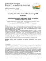
Figure 1.1 is the block diagram of a typical digital communication system. The message to be sent may be fiom an analog source (e.g., voice) or fiom a digital source
(e.g., computer data). The analog-to-digital (AID) converter samples and quantizes
the analog signal and represents the samples in digital form (bit 1 or 0). The source
encoder accepts the digital signal and encodes it into a shorter digital signal. This is
called source encoding, which reduces the redundancy hence the transmission speed.
This in turn reduces the bandwidth requirement of the system. The channel encoder
accepts the output digital signal of the source encoder and encodes it into a longer
digital signal. Redundancy is deliberately added into the coded digital signal so that
some of the errors caused by the noise or interference during transmission through
the channel can be corrected at the receiver. Most often the transmission is in a highfrequency passband, the modulator thus impresses the encoded digital symbols onto
a carrier. Sometimes the transmission is in baseband, the modulator is a baseband
modulator, also called formator, which formats the encoded digital symbols into a
waveform suitable for transmission. Usually there is a power amplifier following
the modulator. For high-frequency transmission, modulation and demodulation are
usually performed in the intermediate frequency (IF). If this is the case, a frequency
up-convertor is inserted between the modulator and the power amplifier. If the IF is
too low compared with the carrier frequency, several stages of carrier frequency conversions are needed. For wireless systems an antenna is the final stage of the trans-
Digital Modulation Techniques
3
Analog
source
_, A/D
+,
I
Source
encoder -# encoder
I
,
Modulator
Power
amplifier
v
Channel
Analog
user
+
DlA
+
Source +,
decoder -
Channel*
Low noise
+ amplifier
decoder Demodulator
I
L-b-1
Digital
Figure 1 . 1
Block diagram of a typical digital communication system.
mitter. The transmission medium is usually called the channel, where noise adds to
the signal and fading and attenuation effects appear as a complex multiplicative factor on the signal. The term noise here is a wide-sense term which includes all kinds
of random electrical disturbance from outside or from within the system. The channel also usually has a limited frequency bandwidth so that it can be viewed as a filter.
In the receiver, virtually the reverse signal processing happens. First the received
weak signal is amplified (and down-converted if needed) and demodulated. Then
the added redundancy is taken away by the channel decoder and the source decoder
recovers the signal to its original form before being sent to the user. A digital-toanalog (DIA) converter is needed for analog signals.
The block diagram in Figure I . 1 is just a typical system configuration. A real
system configuration could be more complicated. For a multiuser system, a multiplexing stage is inserted before modulator. For a multistation system, a multiple
access control stage is inserted before the transmitter. Other features like frequency
spread and encryption can also be added into the system. A real system could be
simpler too. Source coding and channel coding may not be needed in a simple system. In fact, only the modulator, channel, demodulator, and amplifiers are essential
in all communication systems (with antennas for wireless systems).
For the purpose of describing modulation and demodulation techniques and an-
Chapter I
Modulator
Channel
',
Wter
' h(t)
Introdttction
@
@?dl-
Demodulator
n(t)
additive
noise and
interference
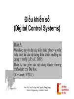
Figure 1.2 Digital communication system model for modulation and demodulation
alyzing their performance, the simplified system model shown in Figure 1.2 will be
often used. This model excludes irrelevant blocks with regard to modulation so that
relevant blocks stand out. However, recently developed modem techniques combine
modulation and channel coding together. In these cases the channel encoder is part
of the modulator and the channel decoder is part of the demodulator. From Figure
1.2, the received signal at the input of the demodulator can be expressed as
where * denotes convolution. In Figure 1.2 the channel is described by three elements. The first is the channel filter. Because of the fact that the signal s ( t ) from the
modulator must pass the transmitter, the channel (transmission medium) and the receiver before it can reach the demodulator, the channel filter therefore is a composite
filter whose transfer function is
where HT( f ), Hc( f ), and H R (f ) are the transfer function of the transmitter, the
channel, and the receiver, respectively. Equivalently, the impulse response of the
channel filter is
where hT(t), hc(t), and h R ( t )are the impulse responses of the transmitter, the channel, and the receiver, respectively. The second element is the factor A ( t ) which is
generally complex. This factor represents fading in some types of channels, such as
mobile radio channel. The third element is the additive noise and interference term
n ( t ) .We will discuss fading and noise in more detail in the next section. The channel
4
Digital Modulation Techniques
model in Figure 1.2 is a general model. It may be simplified in some circumstances,
as we will see in the next section.
1.2
COMMUNICATION CHANNELS
Channel characteristic plays an important role in studying, choosing, and designing
modulation schemes. Modulation schemes are studied for different channels in order
to know their performance in these channels. Modulation schemes are chosen or
designed according to channel characteristic in order to optimize their performance.
In this section we discuss several important channel models in communications.
1.2.1
Additive White Gaussian Noise Channel
Additive white Gaussian noise (AWGN) channel is a universal channel model for
analyzing modulation schemes. In this model, the channel does nothing but add a
white Gaussian noise to the signal passing through it. This implies that the channel's
amplitude frequency response is flat (thus with unlimited or infinite bandwidth) and
phase frequency response is linear for all frequencies so that modulated signals pass
through it without any amplitude loss and phase distortion of frequency components.
Fading does not exist. The only distortion is introduced by the AWGN. The received
signal in ( I . I ) is simplified to
where n ( t )is the additive white Gaussian noise.
The whiteness of n ( t )implies that it is a stationary random process with a flat
power spectral density (PSD)for all frequencies. It is a convention to assume its
PSD as
This implies that a white process has infinite power. This of course is a mathematical idealization. According to the Wiener-Khinchine theorem, the autocorrelation
function of the AWGN is
where & ( T ) is the Dirac delta function. This shows the noise samples are uncorrelated
Chapter 1
Infroduction
5
no matter how close they are in time. The samples are also independent since the
process is Gaussian.
At any time instance, the amplitude of n ( t )obeys a Gaussian probability density
function given by
where ,v is used to represent the values of the random process n ( t ) and o2 is the
variance of the random process. It is interesting to note that a2 = cx, for the AWGN
process since a2 is the power of the noise, which is infinite due to its "whiteness."
However, when r ( t ) is correlated with a orthonormal function @ ( t )the
, noise in
the output has a finite variance. In fact
where
and
The variance of n is
6
Digital Modulation Techniques
Then the probability density function (PDF) of n can be written as
This result will be frequently used in this book.
Strictly speaking, the AWGN channel does not exist since no channel can have an
infinite bandwidth. However, when the signal bandwidth is smaller than the channel
bandwidth, many practical channels are approximately an AWGN channel. For example, the line-of-sight (LOS) radio channels, including fixed terrestrial microwave
links and fixed satellite links, are approximately AWGN channels when the weather
is good. Wideband coaxial cables are also approximately AWGN channels since there
is no other interference except the Gaussian noise.
In this book, all modulation schemes are studied for the AWGN channel. The
reason of doing this is two-fold. First, some channels are approximately an AWGN
channel, the results can be used directly. Second, additive Gaussian noise is ever
present regardless of whether other channel impairments such as limited bandwidth,
fading, multipath, and other interferences exist or not. Thus the AWGN channel is the
best channel that one can get. The performance of a modulation scheme evaluated in
this channel is an upper bound on the performance. When other channel impairments
exist, the system performance will degrade. The extent of degradation may vary for
different modulation schemes. The performance in AWGN can serve as a standard
in evaluating the degradation and also in evaluating effectiveness of impairmentcombatting techniques.
1.2.2
Bandlimited Channel
When the channel bandwidth is smaller than the signal bandwidth, the channel is
bandlimited. Severe bandwidth limitation causes intersymbol interference (ISI) (i.e.,
digital pulses will extend beyond their transmission duration (symbol period T s ) )and
interfere with the next symbol or even more symbols. The IS1 causes an increase
in the bit error probability (Pb)or bit error rate (BER), as it is commonly called.
When increasing the channel bandwidth is impossible or not cost-efficient, channel
equalization techniques are used for combatting ISI. Throughout the years, numerous
equalization techniques have been invented and used. New equalization techniques
are appearing continuously. We will not cover them in this book. For introductory
treatment of equalization techniques, the reader is referred to [ I .Chapter 6 ) or any other
communication systems books.
Chapter 1
1.2.3
Intmduction
Fading Channel
Fading is a phenomena occurring when the amplitude and phase of a radio signal
change rapidly over a short period of time or travel distance. Fading is caused by interference between two or more versions of the transmitted signal which arrive at the
receiver at slightly different times. These waves, called multipath waves, combine
at the receiver antenna to give a resultant signal which can vary widely in amplitude
and phase. If the delays of the multipath signals are longer than a symbol period,
these multipath signals must be considered as different signals. In this case, we have
individual multipath signals.
In mobile communication channels, such as terrestrial mobile channel and satellite mobile channel, fading and multipath interference are caused by reflections from
surrounding buildings and terrains. In addition, the relative motion between the
transmitter and receiver results in random frequency modulation in the signal due
to different Doppler shifts on each of the multipath components. The motion of
surrounding objects, such as vehicles, also induces a time-varying Doppler shift on
multipath component. However, if the surrounding objects move at a speed less than
the mobile unit, their effect can be ignored [2].
Fading and multipath interference also exist in fixed LOS microwave links [3].
On clear, calm summer evenings, normal atmospheric turbulence is minimal. The
troposphere stratifies with inhomogeneous temperature and moisture distributions.
Layering of the lower atmosphere creates sharp refractive index gradients which in
turn create multiple signal paths with different relative amplitudes and delays.
Fading causes amplitude fluctuations and phase variations in received signals.
Multipath causes intersymbol interference. Doppler shift causes carrier frequency
drift and signal bandwidth spread. All these lead to performances degradation of
modulations. Analysis of modulation performances in fading channels is given in
Chapter 10 where characteristics of fading channels will be discussed in more detail.
1.3
BASIC MODULATION METHODS
Digital modulation is a process that impresses a digital symbol onto a signal suitable
for transmission. For short distance transmissions, baseband modulation is usually
used. Baseband modulation is often called line coding. A sequence of digital symbols are used to create a square pulse waveform with certain features which represent
each type of symbol without ambiguity so that they can be recovered upon reception.
These features are variations of pulse amplitude, pulse width, and pulse position.
Figure 1.3 shows several baseband modulation waveforms. The first one is the nonreturn to zero-level (NRZ-L) modulation which represents a symbol 1 by a positive
Digital Modulation Techniques
(b) Unipolar RZ
(c) Bi-a-L (Manchester)
Figure 1.3 Baseband digital modulation examples.
square pulse with length T and a symbol 0 by a negative square pulse with length T.
The second one is the unipolar return to zero modulation with a positive pulse of T/2
for symbol I and nothing for 0. The third is the biphase level or Manchester, after
its inventor, modulation which uses a waveform consisting of a positive first-half T
pulse and a negative second-half T pulse for 1 and a reversed waveform for 0. These
and other baseband schemes will be discussed in detail in Chapter 2.
For long distance and wireless transmissions, bandpass modulation is usually
used. Bandpass modulation is also called carrier modulation. A sequence of digital symbols are used to alter the parameters of a high-frequency sinusoidal signal
called carrier. It is well known that a sinusoidal signal has three parameters: amplitude, frequency, and phase. Thus amplitude modulation, frequency modulation,
and phase modulation are the three basic modulation methods in passband modulation. Figure 1.4 shows three basic binary carrier modulations. They are amplitude
shift keying (ASK), frequency shift keying (FSK), and phase shift keying (PSK). In
ASK, the modulator puts out a burst of carrier for every symbol 1, and no signal
for every symbol 0. This scheme is also called on-off keying (OOK). In a general
ASK scheme, the amplitude for symbol 0 is not necessarily 0. In FSK, for symbol
I a higher frequency burst is transmitted and for symbol 0 a lower frequency burst
Chapter 1
1
0
Introduction
1
1
FSK
V V V M V WVVVUVVVM
vW
PSK
Figure 1.4 Three basic bandpass modulation schemes.
is transmitted, or vice versa. In PSK, a symbol I is transmitted as a burst of carrier
with 0 initial phase while a symbol 0 is transmitted as a burst of carrier with 180'
initial phase.
Based on these three basic schemes, a variety of modulation schemes can be derived from their combinations. For example, by combining two binary PSK (BPSK)
signals with orthogonal carriers a new scheme called quadrature phase shift keying
(QPSK) can be generated. By modulating both amplitude and phase of the carrier,
we can obtain a scheme called quadrature amplitude modulation (QAM), etc.
1.4
CRITERIA OF CHOOSING MODULATION SCHEMES
The essence of digital modem design is to efficiently transmit digital bits and recover
them from corruptions from the noise and other channel impairments. There are
three primary criteria of choosing modulation schemes: power efficiency, bandwidth