RESEARCH MIXTURE FORMATION AND COMBUSTION OF DUAL FUEL ENGINE (BIOGAS DIESEL)
Bạn đang xem bản rút gọn của tài liệu. Xem và tải ngay bản đầy đủ của tài liệu tại đây (922.56 KB, 27 trang )
MINISTRY OF EDUCATION AND TRAINING
THE UNIVERSITY OF DANANG
NGUYEN VIET HAI
RESEARCH MIXTURE FORMATION AND
COMBUSTION OF DUAL FUEL ENGINE
(BIOGAS-DIESEL)
Specialty: Heat Engine Engineering
Code: 62.52.34.01
ABSTRACT OF TECHNICAL THESIS
ĐA NANG – 2016
The work has finished at
THE UNIVERSITY OF DANANG
The first scientific advisor: Prof. Bui Van Ga, Dr. of Sc
The second scientific advisor: Ass.Prof. Duong Viet Dung, Dr
The first reviewer: Ass.Prof. Nguyen Hoang Vu, Dr
The second reviewer: Prof. Pham Minh Tuan, Dr
The third reviewer: Ho Si Xuan Dieu, Dr
The thesis is going to be defended at the Council for Evaluation PhD
thesis Technical meeting at The University of Da Nang on 05 Month
11 year 2016
This thesis can be lookup at:
- Learning Information - Resource Center, the University of Danang.
- Learning Resource Center, the University of Danang.
1
INTRODUCTION
THE REASON FOR CHOOSING: Saving energy and reducing
environmental pollution are the objectives of automobile industry and car
(automotive industry). Biogas is a renewable energy source derived from
solar power, so using it does not increase the concentration of CO 2 in the
atmosphere. Biogas has been thriving not only in the developing
countries but also in the developed countries. To meet the diverse needs
of the application of biogas in internal combustion engines, technology
solutions converting the traditional engine to biogas are necessary. In
order to predict the size of the converter transforming from each kind
diesel engine into dual fuel diesel-biogas engine works with many
different sources of biogas, we must conduct simulation researches and
evaluate the results with experimental data in a number of specific cases
[16].
For the above reasons, the topic "Research mixture formation
and combustion of dual fuel engine (biogas-diesel)" is very urgent; it
not only contributes to diversify fuel sources for heat when the engine is
running out of oil, but also contributes to more efficient use of biogas fuel
source for internal combustion engines.
PURPOSE OF STUDY: Perform the basic research on combustion
and fuel supply for dual fuel biogas-diesel engine outside the purpose of
reducing environmental pollution, increasing the availability of fuel for
internal combustion engines; the thesis also aims at using this biofuel
alternative source widely to combustion engines in an effective way.
SUBJECTS AND SCOPE OF THE STUDY
Subjects of study: The combustion in Vikyno EV2600-NB dual
fuel engines using biogas-diesel fuel is selected as the thesis research
object.
Scope of the study: Due to the complexity of the research
problem, this thesis is limited and focused on the mixture formation and
combustion in EV2600-NB dual fuel engines using biogas-diesel fuel by
2
modeling and experimental research.
RESEARCH METHODS: Thesis uses theoretical research,
modeling combined with empirical research methods.
Theoretical research and modeling: Research the mixture
formation of the Vikyno EV2600-NB dual fuel engine (biogas-diesel) by
means of suction through the throat Venturi by GATEC-20 to establish
the curve of the rate coefficient of dynamic equivalent load muscle;
research modeling biogas combustion-air mixture ignited by jet bait to
predict economic features and technology of the engine to the operating
modes and different fuel components. Modeling results help reducing
experimental costs.
Experimental study: Experimental measurements of pressure
changes in the combustion chamber of the Vikyno EV2600-NB dual fuel
engine (biogas-diesel) fuel uses diesel and biogas fuels with different
components ignition CH4 by priming jet; Experimental studies mixture
formation of the dual fuel engine to establish characteristic curves of
coefficients equivalent rate under engine load; compare results by
modeling and experimentation.
SCIENTIFIC MEANING AND REALITY OF THE STUDY:
Scientific significance: The thesis has contributed to basic
research and depth of dual fuel engines (biogas-diesel) in Vietnam.
Reality significance: The thesis will identify the efficiency of
using biogas fuel for internal combustion engines and reduce
environmental pollution.
THESIS CONTENT STRUCTURE
The layout of the thesis beyond the introduction, conclusion and
direction of development of the subject, the content is presented in four
chapters with the following structure:
Chapter 1: Overview
Chapter 2: Simulation research mixture formation and
combustion of dual fuel engine (biogas-diesel)
3
Chapter 3: Experiments study
Chapter 4: Comparison of the results given by simulation and
experimental dual fuel engine biogas-diesel
CONTRIBUTION NEW SCIENTIFIC ASPECTS OF THE
THESIS:
The thesis has some new contributions in science as follows:
Thesis experimentally determined characteristic lines of
equivalent coefficient ratio according to load and engine speed, the
results were compared with the model was calculated previously.
The thesis has developed computational models mixture
formation and combustion of dual fuel engine (biogas-diesel) thereby
orientating during testing to evaluate the usability of mobile this muscle.
The thesis points out the characteristics of the combustion of
fuel biogas methane corresponding components in different fuels, thereby
allowing analysis accurately assess the parameters affecting engine
features dual fuel (biogas-diesel).
Chapter 1
OVERVIEW
1.1. ISSUES OF ENERGY AND ENVIRONMENT TODAY
1.2. CHARACTERISTICS OF BIOGAS USED FOR INTERNAL
COMBUSTION ENGINES
Biogas is produced from the anaerobic degradation of organic
compounds. Essential components of are methane (CH4) and carbon
dioxide (CO2). Organic waste from different sources can be used to
produce biogas.
1.3. APPLIED RESEARCH BIOGAS FOR COMBUSTION
ENGINES
1.3.1. Research and application of biogas in the world
Internal combustion engines using biogas as fuel can be used
engines or fuel gas converted from the engine using traditional liquid
fuels. Engines using biogas fuel from the engine renovated using
4
traditional liquid fuels can be the engine ignition cramp or dual fuel
engine. Dual fuel injection engine is about 10% to 20% of diesel fuel
primer widely used in small power range because of the highly efficient
power generation. However, it emits the higher contamination levels. On
the other hand, this approach has the advantage that without biogas, the
engine can still run entirely by diesel [8], [21], [22], [24].
Clark (1985) [38] said that when switching engine uses natural
gas to biogas, power run down about 5 ÷ 20% compared with the natural
gas. Jewell et al. (1986) [59] suggest that running biogas with 60% CH4
reduces engine capacity from 15 ÷ 20%. Derus (1983) [43] proposed
composition of methane in biogas minimum for 4-stroke engine with a
calorific value of 35% 14,89MJ/m3.
1.3.2. Research and application of biogas in VietNam
In 2007 the team of Prof. Dr. Bui Van Ga has conducted research on
the use of biogas engines [7]. And they tested to run on biogas with the
110cc motorcycle accessories GA5. Besides, the research team has
published studies provide biogas systems for traction motor generator
system presents 2HP offers complete biogas for combustion engines
clusters - generator [8]. In 2008, Prof. Bui Van Ga and his colleagues
published the research on biogas systems offer dual-fuel engines for
biogas-diesel [8]. In 2009, Prof. Bui Van Ga and his colleagues continued
to study system providing multiple cylinder engines sized two fuels [6].
In 2013, Nguyen Van Dong has successfully applied research
biogas fuel used for motorcycle [25]. Also in 2013, Le Xuan Thach has
researched and published the results in transforming diesel into biogas
engine ignition forced to run biogas [22]. Le Minh Tien (2013) at the
University of Da Nang has studied the design and manufacture of motor
fuel used two biogas / diesel on the basis of a cylinder engine [21].
However, the aforementioned study was not conducted
measurements of exhaust gas emissions engine. When converting diesel
engines to run biogas, authors have just compared the features of this
5
engine with the original diesel through the engine's power and special-use
simulation software. In order to assess more accurately, we need to
measure the pressure gauge indicating the engine combustion chamber. In
the course of providing fuel mixture biogas/diesel, we should determine
their density in experiments.
1.4. CONCLUSION
The overview research results of the use of biogas for internal
combustion engine allows drawing the following conclusions:
- Studies in production and application of renewable energy
sources have been widely deployed. One of them is research using biogas
used as fuel for internal combustion engines in stationary purposes and
motor vehicles. Solutions using biogas as a fuel for internal combustion
engines achieves all 3 objectives: saving fossil fuels, limiting emissions
of greenhouse gases and protecting the environment in the production and
activities.
- Biogas is a renewable energy derived from solar energy; the use
does not increase the concentration of greenhouse gases in the
atmosphere. The presence of CO2 in biogas reduces fuel heating value
and fire rate. However, it increases resistance to detonation of fuel,
allows increasing compression ratio of the engine.
So "Research mixture formation and combustion of dual fuel
engine (biogas-diesel)" has scientific and practical significant. The results
will partly contribute to the process of solving the above problems;
especially to create a premise and a solid basis for the production of nextgeneration dual fuel engine (biogas-diesel) work with high efficiency and
capacity; low fuel consumption rate brings economic efficiency for the
country.
Chapter 2
RESEARCH AND SIMULATION PROCESS OF FORMATION OF
MIXED AND FIRE DUAL FUEL ENGINE (BIOGAS-DIESEL)
6
2.1.THEORY
OF
INJECTION
DIESEL
DEVELOPMENT
IN
COMBUSTION CHAMBER DUAL FUEL ENGINES (BIOGAS DIESEL)
2.1.1. Equations of Motion for Particles
2.1.2. Stochastic Particle Tracking in Turbulent Flow.
2.1.3. Droplet Vaporization
2.2.THE
DEVELOPMENT OF JET DIESEL IN THE BIOGAS-AIR
MIXED.
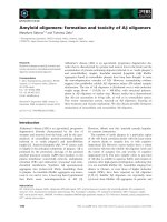
Diesel includes stable molecules such as C12H22, C13H24 and
C12H24. Normally, people use the average chemical composition of diesel
0.16
0.016
0.12
0.012
0.08
0.008
Hơi diesel
DPM
0.04
0.004
0
0
0
5
10
15
20
25
Mass density of the fuel particles (kg/m3)
Diesel vapor concentration (%)
C12H23. Diesel spontaneously burn at combustion temperature 2100C.
30t[ms]
Figure 2.3: The development of Jet diesel in the biogas-air mixed (p=3[bar])
We can easily find out that after the end of injection at the time
of 5ms, jet started strongly decaying into particle fuel cloud, going away
from the nozzle mouth. When cloud particles volume expansion, fuel
particles accelerated evaporation, decreasing the amount of grain and fuel
vapor concentration in the combustion chamber increases.
7
2.3.DEVELOPMENT
JET DIESEL ENGINE COMBUSTION
CHAMBER BIOGAS FUEL USING WITH DIFFERENT
INGREDIENTS CH4
2.3.1. Component mixture
2.3.2. Conditions jet Diesel
Combustion chamber used in simulation calculations Cylinder,
diameter 140 mm, height 300 mm, volume 4.62 liters. Airflow can be
used to burn completely 0.4 g diesel.
2.3.3. Effects of combustion chamber pressure
Just as case of the fuel injection in the atmosphere or
environment containing air and CH4, we find that in the same conditions,
when the pressure in the combustion chamber is increased, the fuel vapor
concentration in the combustion chamber reduces.
2.3.4. Effect of temperature on the development mixture of jet
Just as in the case of diesel injection air environment containing
CH4, biogas-air mixtures when temperatures rise, the diesel fuel vapor
concentration in the mixture also increased due to rapid evaporation of
fuel at high temperatures.
2.3.5. Effect of biogas fuel
When components CH4 biogas increases not only in improved
combustion but also improved the condition of the jet diesel evaporation
leads to improved quality spark jet primer.
2.3.6. Effect of flow injection
The calculation results show that when traffic jet increases, diesel
fuel vapor concentration at a given time after spraying has also increased.
Growth rate of the fuel vapor concentration is greater when higher jet
flow rate of fuel vapor concentrations increase speed while jet little. Due
to the mixture which evaporates quickly, enabling the combustion takes
place completely we should increase traffic jet but decrease time jet to
ensure fuel supply cycle does not change.
8
2.4. STUDY COMBUSTION OF MIXED BIOGAS -AIR SPARK JET
PRIMER DIESEL
2.4.1. Equivalent coefficients and mixture compositions f
In this section, we study the combustion of biogas-air mixture in the
combustion chamber isometric cylinder diameter of 140mm and a height
of 300mm.
a.
b.
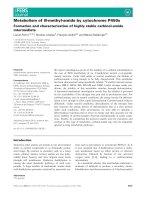
Figure 2.32: Simulation combustion of biogas-air mixture ignited by primers jet
diesel (a) and forced ignition by sparks (b)
We
clearly
see
the
1.1
difference of 2 ignition cases. In
1
the case of ignited by sparks, the
0.9
membrane-shaped pompoms fire
0.8
f=0,075
spreads from ignition candle
f=0,13
0.7
farthest
regions
of
the
combustion chamber. In the case
0.6
of diesel spark jet primers,
0.5
combustion starts from the top
jet in random shapes, when the
fire moved away membranes, jet
t[ms]
0
15
30
45
60
75
Figure 2:33: The variation coefficient of equivalent
-time (M6C4, p=3[bar], T=750[K], Q=0,01[kg/s],
tjet=4[ms])
area remained slightly lower temperature than the temperature in the
combustion chamber of the mixture.
Equivalent coefficient rose in diesel fuel injection period and then
9
stabilized during the fire. Shape of the curve barely changed when changing
the mixture ratio
2.4.2. Varying pressure and temperature in the combustion chamber
mixed
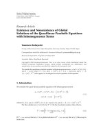
We recognize that initial component mixture increases the pressure and
temperature of the mixture is increased. When the mixture starts making
bold, f increases pressure and decreases temperature due to incomplete
combustion mixture.
15
2600
p[bar]
T[K]
12
2200
1800
9
f=0,03
f=0,03
f=0,05
1400
f=0,05
f=0,07
f=0,07
6
f=0,09
f=0,09
f=0,11
1000
f=0,11
600
3
0
15
30
45
60
75
0
15
30
45
60
75
Figure 2.36 : Varying the pressure in the t[ms] Figure 2.37: Mixture temperature variation in
combustion chamber (M8C2, p=3[bar],
the combustion chamber (M8C2, p=3[bar],
T=750[K], Q=0,01[kg/s], tjet=4[ms])
T=750[K], Q=0,01[kg/s], tjet=4[ms])
t[ms]
2.4.3. The influence of various factors on the efficiency of combustion
2.4.3.1. The influence of the amount of diesel fuel injection
In the poor mixed conditions, the amount of diesel jet significantly
increased the pressure in the combustion chamber with M6C4. When
using fuel M8C2, the degree of difference of pressure jet spray primers
and primers is not large.
2.4.3.2. The influence of mixture components
We see in all cases, the growth pressure when f little is lower than
large f.
2.4.3.3. The influence of fuel
10
We found that when using a poverty of mixture, the impact of
variable fuel to pressure is trivial. However, when using the wealthy
mixture, level pressure difference when using fuel M8C2 and M6C4
changed significantly.
2.5. CONCLUSION
From the above results, we draw the following conclusions:
- Evaporation of the diesel jet in air environment close to the
environment of CO2 in the combustion chamber pressure conditions close
to the environment of low and CH4 in conditions of high pressure
combustion chamber. The effect of air-biogas mixture combustion
chamber depends on the rate of CH4 /CO2 in the fuel.
- In the same condition and component jet solvent mixture, diesel
beam evaporation of the combustion chamber when the pressure
decreased but increased sharply increases with increasing temperature of
the mixture in the combustion chamber. Diesel fuel vapor concentrations
decreased 2 to 3 times when the pressure increased from 3[bar] to 5[bar]
in the same temperature conditions.
- The same conditions, when the pressure in the combustion chamber
is increased, the fuel vapor concentration in the combustion chamber
reduces diesel. Biogas mixtures when temperatures rise, the air-vapor
concentration in the mixture diesel fuel also increased.
- When ignited by flame bait, the ignition point appears at the top jet,
screen fire randomly shaped. Compared with forced ignition, speed
increased pressure in the combustion chamber when the spark higher
spray primer
- The pressure in the combustion chamber reaches the maximum
value when the equivalent ratio of general mixture at about 1.01
- In the same operating conditions, temperature, maximum
pressure in the combustion mixture dual fuel engine combustion chamber
increases the concentration of CH4 in biogas increase. Combustion
pressure increased by 3% while increasing component in biogas CH 4
11
from 60% to 80% when mixed with a coefficient equal to 0.5; this level
of increase to 20% to the coefficient equivalent of 1.01.
Chapter 3
EXPERIMENTS STUDY
3.1. STUDY EQUIPMENT
3.1.1. Experiment engine
Experiment engine is a dual fuel engine biogas - diesel when
converting EV2600-NB diesel engines to dual fuel biogas-diesel engine
3.1.2. Dynamometer engine power APA 204
APA dynamometer 204 (asynchron Pendelmaschinen Anlage)
can measure the power and torque of the engine through sensors
experiment is mounted by the dynamometer.
3.1.3. The system for measuring pressure combustion chamber of
internal combustion engines - indiset 620
Pressure variation in the cylinder indicator was recorded by
pressure sensors GU12P and the speed is determined by engine speed
sensor Encoder 364C [34], [35], [36].
3.1.4. Equipment intake air flow measurement and biogas flow
provides dual fuel engine
3.2. EXPERIMENTS AND EVALUATION OF RESULTS
3.2.1. Layout and process laboratory testing on a dynamometer
engine
12
3
2
4
5
6
7
9
8
10
11
12
15
13
1
14
Figure 3.15: Laboratory layout dual fuel engine (biogas - diesel) on a
dynamometer engine
3.2.2. Experimental results Analysis
3.2.2.1. Analysis the experimental results determined equivalent factor
From the simulation results and the results of running, we conduct
experiments to identify the relative size of the delivery orifice with each
biogas fuels with different components.
Table 3.4: The diameter of the hole in the fuel grade biogas
Biogas fuel
Hole diameter main level [mm]
60%CH4
70%CH4
80% CH4
17,07
14,83
13,59
With supply biogas pipe diameter selected for CH4 biogas containing
various components, the relationship between the ratio equal and open the
throttle does not differ much.
3.2.2.2. Experimental results Analysis combustion dual fuel engine
a. Features diesel and dual fuel engine (biogas - diesel)
In this study, early injection angle of the motor is fixed in value s
= 22,25 before DCT. Public cycle with 100% of the maximum injection
is 1180.55J/cyc; while the cycle of the engine when the injection 50% of
the maximum injection was 607.39J/cyc, ie only by 51.45% compared to
13
the maximum spray. Public motor cycle when running through biogas
containing 60%CH4 in the above condition is 851,65J/cyc, by 72% to
100% of the diesel spray maxima (Figure 3.22).
pi [bar]
pi [bar]
Diesel (1)
80
80
Biogas (60%CH4)
Diesel (1)
Diesel (2)
60
60
Biogas (60%CH4)
40
40
20
20
Diesel (2)
[0CA]
0
180
240
300
360
420
480
0
540
0.0
0.2
0.4
0.6
0.8
1.0
1.2
V [liter]
Figure 3.21: The pressure in the cylinder of the
engine at speed n = 2000[rpm]when diesel to
100% of maximum injection (diesel (1)), 50% of
the maximum injection (diesel (2)) and the
Figure 3.22: Graph of the motor at speed
n=2000[rpm] when not fitted diesel mixtures
(diesel (1)), when mounting the mixtures
(diesel(2)) and when powered by biogas
powered by biogas containing 60% CH4 with = 1
containing 60%CH4 with = 1
b. The influence of the throttle to the pressure indicated in dual fuel
engine cylinder
Pressure graph with =1 and =1.05 is almost identical and have
the maximum pressure value. When the equivalent ratio is lower, the
maximum peak pressure also decreased and shifted DCT
100
80
pi [bar]
pi [bar]
100 division = 1,05
100 division = 1,05
80
80 division = 1,0
80 division = 1,0
60
60 division = 0,8
60 division = 0,8
60
40 division = 0,58
40 division = 0,58
20 division = 0,3
40
20 division = 0,3
40
20
20
0
180
[0CA] 0
240
300
360
420
480
540
Figure 3.23: The influence of the throttle to the
pressure in the cylinder (20, 40, 60, 80, 100%
throttle; 80% CH4; n = 1800rpm)
180
240
300
360
420
480
[0CA]
540
Figure 3.24: The influence of the throttle to the
pressure in the cylinder (20, 40, 60, 80, 100%
throttle; 80% CH4; n=2000rpm)
14
c. The influence of the concentration of CH4 in the biogas to the pressure
in the cylinder dual fuel engine
The same operating conditions, the maximum pressure in the
cylinder increases CH4 content in the biogas. Peak pressure curve as far
DCT translate the content of CH4 in biogas reduction. This can be
explained by the firing rate of the mixture decreases with increasing
levels of CO2 in biogas.
d. The influence of the motor speed to the pressure in the cylinder dual
fuel engine
Results showed that when the engine speed increases, the
maximum pressure of the cycle resulting in the reduction cycle indicator
decreased. This can be explained by the mixture of biogas-air has low
burn rate compared to traditional fuels, so when the engine speed
increases, the time for combustion to decrease, leading to fire and not
totally, reduces the engine directive.
e. Influence of ratio equivalent to the directive cycle dual fuel engine
1200
1200
Wi [J/cyc]
1000
1000
800
800
600
600
400
400
200
0.2
0.4
0.6
0.8
1
1.2
1.4
1.6
Figure 3.28: The relationship between the
indicator cycles and equivalent ratio when
running at speed up with n = 2000[rpm] with
biogas contains 60%CH4 (), 70%CH4 () và
80%CH4 (); Db=18mm)
Wi [J/cyc]
The throttle opening
[% ]
200
20
40
60
80
100
Figure 3.29: Effects of fuel to curve the indicator
variable according throttle aperture (%)
(n=1800[rpm]; biogas contains 80%CH4(),
70%CH4(), 60%CH4(); Db change)
Figure 3.28 shows the cycle indicator reaches its maximum value
when the mixture slightly rich, approximately =1.1. Public directive
cycle equivalent reduces ratio when greater or smaller than this value.
15
Theoretically, when =1 the optimal mixture of fire and therefore also the
position that the cycle reaches the maximum value. For biogas as fuel
containing CO2 fire so speed is slowed down. In the other hand, due to
the inert gas content in the mixture increases should be locally incomplete
combustion. Because of these reasons, we should provide the amount of
fuel into the combustion chamber greater than the theoretical amount of
fuel to ensure the highest performance engine.
Such characteristic lines outside of engine fuel biogas-diesel dual
characteristic roads built with =1,1.
f. Effects of CH4 in biogas components to the cycle indicator of the dual
fuel engine according to the throttle opening
Pe [kW]
1200
Wi [J/cyc]
18
Diesel
16
Biogas(80%CH4)
14
1000
12
10
800
Biogas(60%CH4)
8
600
1200
n [rpm]
1400
1600
1800
2000
2200
6
1200
1400
1600
1800
2000
n [rpm]
2200
Figure 3.32: Effects of CH4 in biogas
components to the cycle varies according to
engine speed (biogas contains 80% CH4() and
Figure 3.33: Compare outer curve of the
diesel engine primitive and when
powered by biogas containing 80%,
60% CH4(), =1,1)
60% CH4 with = 1.1
Along with the same throttle valve aperture, the directive
increases the engine's components in biogas CH4.
Provide biogas pipe diameter is determined with equivalent
coefficient = 1.1 when the engine works at rated speed mode with the
lowest CH4 biogas composition.
g. Effects of CH4 in biogas components to the cycle indicator of the dual
16
fuel engine according to engine speed
As engine speed increases the time for combustion to reduce fuel
consumption in combustion process also leads to the reduction of the
engine cycle is reduced.
h. Compare outer curve and motor performance of dual fuel engine
At rated speed mode n=2200rpm, the power of dual fuel engine
run with biogas containing 80% CH4 reduction of 12% compared with the
diesel. When running on biogas containing 60% CH4, the extent of this
reduction of up to 25% (Figure 3.33).
0.86
m
m
0.9
Biogas(80%CH4)
0.85
0.88
Biogas(80%CH4)
Biogas(70%CH4)
0.84
0.86
0.83
0.84
Biogas(60%CH4)
Biogas(60%CH4)
The throttle opening
0.82
1200
n [rpm]
1400
1600
1800
2000
2200
Figure 3.34: Motorized performance
variation of the dual fuel engine according
to engine speed when running on biogas
containing 60%CH4 and 80%CH4
[%]
0.82
20
30
40
50
60
70
80
90
100
Figure 3.35: Motorized performance variation
of the dual fuel engine according to the throttle
when running on biogas containing 60% CH4,
70% CH4 and 80%CH4
However, capacity reduction of switching to diesel-powered
small biogas than capacity reductions when transferring gasoline engine
to run on biogas (this reduction may be up to 40%). This is an
outstanding advantage when transferring diesel to run on biogas.
Motorized performance is determined m = Pe/Pi. This is an
important parameter to predict the useful capacity of the calculation
engine combustion simulation. This result shows a slight decrease
Motorized performance according to engine speed. This may explain the
17
increased engine speed; friction losses increase with so useful power of
the engine is reduced. In the working level of the engine from 1800[rpm]
to 2200[rpm], Motorized performance from 0.82 to 0.86 change (Figure
3.34). Figure 3.35 shows the performance ranged from 0,82 to 0,89.
Expanding the throttle, the pressure in the cylinder increases the friction
leads to reduced Motorized performance of the engine.
3.3. COMPARISON OF THE RESULTS GIVEN BY SIMULATION
AND EXPERIMENTAL DUAL FUEL ENGINE BIOGAS -DIESEL
3.3.1. Comparison of pressure directive variations combustion
engine and the cycle directive of dual fuel engines.
Figure 3.36, Figure 3.37 shows the pressure in the engine
cylinder for by higher pressure simulation experimental for grubs in
combustion and expansion.
80
pi [bar]
pi [bar]
80
Simulation
Experimental
60
40
40
20
20
0
180
Simulation
Experimental
60
[0CA] 0
240
300
360
420
480
540
Figure 3.36: Pressure variations in
engine cylinder dual fuel biogas-diesel
as biogas containing run by 80%CH4 at
speed 1600rpm
180
240
300
360
420
480
[0CA]
540
Figure 3.37: Pressure variations in
engine cylinder dual fuel biogasdiesel as biogas containing run by
70%CH4 at speed 1600rpm
The maximum pressure given by higher simulation experimental
maximal pressure of between 3% and 10%. The difference between the
two results as high the content of CH4 in biogas as little. The differential
pressure values given by simulations and experimental can be explained
by the reasons:
18
(1) Simulation of fire spreading speed monitors biogas
composition according to the actual higher models due to the presence of
CO2 in the combustion mixture burning speed affects larger than
expected
(2) Simulation ignition (cylinder heat source) in model
calculations differ with reality takes place in dual fuel engine combustor
(Fire diffusion jet);
(3) Heat transfer between the refrigerant and the cylinder work in
the model does not include detailed component combustion radiation
diffusion priming jet
During compression, the higher the pressure simulation pressure
reduces the experimental simulation directive. Conversely pressure on
road expansion simulate higher pressure increases the experimental
simulation directive. Public cycle directives given by the simulation
higher experimental value by about 10% with 60% biogas containing
CH4 and 3% with biogas containing 80% CH4.
1300
Wi [J/cyc]
1200
1200
Simulation
Experiment
al
Wi [J/cyc]
Simulation
Experiment
al
1000
1100
1000
800
900
800
[%]CH4
60
64
68
72
76
80
Figure 3.42: Compare of cycle directive for by
simulation and experiment as dual fuel
engines run on biogas contains various CH4
600
0.7
0.8
0.9
1
Figure 3.50: Variability of cycle directive
for by simulation and experimental
coefficient equivalent
Pressure difference between simulation and experiment takes
place mainly on the road compression. When as little, the level
19
difference between of directive given by the simulation and experimental
greater. The level difference of 3% when = 1 and 10% when = 0,6.
The analysis results of pressure variations in the cylinder above
shows the maximum difference between the indicator given by simulation
and experiment than 10% in one of the variables: composition CH 4 in
biogas, generation equivalent number and engine speed when the other
parameters held constant.
3.3.2.
Comparative features of dual fuel engine for by simulation
and experimental
3.3.2.1. So compare useful variation capacity of dual fuel engines
coefficient equivalent to by simulation and experiment
12
Wi [J/cyc]
1200
Simulation
Experimental
1000
Pe [kW]
10
Simulation
Experimental
8
800
6
600
4
400
200
0.2
0.4
0.6
0.8
1
1.2
1.4
1.6
Figure 3.55: Variability of cycle directive
equivalent coefficient when the engine runs at
n=1300 [rpm] with Biogas 80%CH4.
2
0.2
0.4
0.6
0.8
1
1.2
1.4
Figure 3.58: Variability of useful capacity of dual
fuel engine coefficient equivalent to engine
running at n = 1300 [rpm] with Biogas 80% CH4.
Results compare on this form gives us our comments:
(1) The varying curve general rule is to have a value at which
of cycle directive reached a maximum value;
(2) Simulation curve reaches maximum value with 1, whereas
experiment curve reaches maximum value with 1,1;
(3) The difference between of directive given by simulations and
experiment under 10% in all operating modes.
Useful simulation capacity is calculated from public directive
20
cycle and Motorized performance. In experimental studies we have
identified Motorized performance of dual fuel engine in the range of 0.82
to 0.86. In this calculation we choose Motorized performance values m =
0.85. Results comparisons shows the variation of the useful power a dual
fuel engine for simulation by matching power by experiment useful for
performance value motorized m = 0.85.
3.3.2.2. Compare outer curve of dual fuel engines for by simulations and
experiments
The research results of directive variable cycle the engine
experiment showed The cycle directive reached a maximum value to
coefficient equivalent value of 1.1 slightly richer than stoichiometric
values = 1 theory. So outside curve of dual fuel engine are built upon
adjustment coefficient equivalent =1,1. According to the results study
by the graph of pressure for simulation and experimentation above the
cycle of directive given by the larger simulation of directive given by the
experiment cycle of about 8%
Wi[J/cyc]
1400
Wi[J/cyc]
1200
80%CH4
Simulation
Experimental
80%CH4
1100
1200
1000
1000
900
800
800
60%CH4
700
Simulation
Experimental
n [rpm]
600
800
1000
1200
1400
1600
1800
2000
2200
Figure 3.61: Variability of cycle directive
according to the engine speed when running
on biogas containing 60% and 80% CH4 for
by simulations and experiment.
60%CH4
n [rpm]
600
800
1000
1200
1400
1600
1800
2000
2200
Figure 3.62: Variability of cycle directive
according to the engine speed by simulating with
coefficient of 0.92 is compatible with the directive
given by the experiment
21
Pe [kW]
18
Capacity directive of
of engine is proportional to
14
the
and
12
engine speed. Due to of
10
cycle
cycle
directive
directive
decreased
Diesel
16
Biogas 80%CH4
8
Biogas 60%CH4
6
when engine speed should
increase
power
according
to
the
curve
n [rpm]
4
800
1000
1200
1400
1600
1800
2000
2200
Figure 4.28: Compare outer curve of dual engine
speed with biogas containing 60% fuelchay CH4 and 80%
directive nonlinear engine.
CH4 for by simulation and experiment, m = 0.85.
We see the results given by simulation is consistent with experiment
results by. Compared with diesel power at speeds primitive norms in
2200rpm, dual fuel engine capacity less than about 12% when running on
biogas containing 80% CH4 and less than 25% when running on biogas
contains 60% CH4.
3.4. CONCLUSION
Research results above allow us to draw the following conclusions:
- The maximum pressure in the cylinder as well as the cycle
indicator decreased while reducing component in biogas CH4 and/or
engine speed due to the presence of CO2 in biogas reduces the burning
speed. In these cases, increasing the spray angle early is necessary to
guarantee engine features.
- Equivalent coefficient of mixtures varies considerably over the
throttle but little change with engine speed. Public directive of engine
cycles for simulations by achieving maximum value with = 1 when the
engine run at a given speed by biogas has given component. Public directive
given by the experiment cycle reaches its maximum value with = 1,1.
When the equivalent ratio is bigger or smaller than this value, the
indicator of engine cycles are reduced.
- The maximum power EV2600-NB dual fuel biogas-diesel
engine when running at rated speed 2200rpm when the power is lower
22
than 12% diesel with biogas containing 80%CH4 and 25% to with biogas
containing 60%CH4. In the same working conditions, the pressure in the
cylinder, the cycle indicator and useful capacity of the engine increases
CH4 content in the biogas. At rated speed mode, the EV2600-NB engine
cycle 10% discount when transferring from biogas containing 80% CH 4
down 60% CH4.
- Motorized performance of dual fuel biogas-diesel engine is in
the range of 0.82 to 0.89. Motorized performance decreases as the engine
speed increases and / or when increasing the throttle opening.
- The presence of CO2 in biogas as fuel reduction burning rate of the
mixture. Therefore, to achieve high efficiency, we need to increase the
injection angle soon when the component in biogas CH4 decreased or when
engine speed increases
- Can use simulation methods to predict the features the dual fuel
engine work. Public directive of engine cycles for simulations by of directive
larger experiment cycle about 8% when the engine speed range from
1000[rpm] and 2000[rpm].
CONCLUSION AND DEVELOPMENT TREND
The research results of the thesis allows us to draw the following
conclusions:
1. CONCLUSION
1. Evaporation of the diesel jet in air environment near environment
of CO2 in the combustion chamber pressure conditions close to the
environment of low and CH4 in conditions of high pressure combustion
chamber. Effects of air-biogas mixture combustion chamber depends on the
rate of CH4/CO2 in the fuel. Under the same conditions injection and
component solvent mixture, diesel beam evaporation of the combustion
chamber decreased when the pressure increases but increased sharply with
increasing temperature of the mixture in the combustion chamber. Diesel fuel
vapor concentrations decreased 2 to 3 when the pressure increased from 3
[bar] to 5 [bar] in the same temperature conditions.
23
2. When ignited by flame bait, the ignition point appears at the top
of jets, membranes randomly shaped fire. Speed increases the pressure in the
combustion chamber when the spark primer spray higher when ignited by
sparks. When the concentration of CH4 in biogas increases, the temperature
and the maximum pressure of the mixture in the combustion dual fuel engine
increases. Combustion pressure increased by 3% while increasing component
in biogas CH4 from 60% to 80% when mixed with equal ratio = 0,5; This
level of increase to 20% for equivalent coefficient = 1,01.
3. In the same working conditions, when the pressure in the
combustion chamber increases, the diesel fuel vapor concentration in the
combustion chamber decreased. When the temperature of air-biogas mixture
increases the concentration of vapor in the mixture of diesel fuel also
increased. The same amount of injection, when injection traffic increases
over time, the evaporation rate of diesel fuel particles increases. Therefore to
improve the process of evaporation and ignition of the dual fuel engine
biogas-diesel we should shorten the time but increasing flow injection.
4. Diameter tubes provide biogas for EV2600-NB dual fuel biogasdiesel engine optimization vary by component CH4 and valuable 17.07mm
with biogas containing 60%CH4, 14.83mm with biogas containing 70% CH4
and 13.59mm with biogas containing 80% CH4.
5. As calculated simulation the pressure in the combustor reaches at
maximum value when the equivalent ratio of general mixture in the
combustion chamber at about 1,01. In experimental public cycle indicator of
the dual fuel biogas-diesel engine reaches the maximum value equivalent
coefficients of about 1,1. When the equivalent ratio greater or smaller than
this value, the indicator of engine cycles are reduced. Deviation of directives
given by the model and experimentally decreased as approaching fire
completely value theory.
6. The same working conditions, the pressure in the cylinder, the cycle
indicator and useful power of the engine increases with the concentration of
CH4 biogas. At rated speed mode, the EV2600-NB engine cycle 10%