Effects of Water Invasion to Design and Production Procedure in Fractured Basement Reservoir, SuTu Den oil Field and Prevention Solutions
Bạn đang xem bản rút gọn của tài liệu. Xem và tải ngay bản đầy đủ của tài liệu tại đây (4.5 MB, 36 trang )
VNU Journal of Science : Earth and Environmental Sciences, Vol. 31, No. 1 (2015) 49-66
Effects of Water Invasion to Design and Production Procedure
in Fractured Basement Reservoir, SuTu Den oil Field and
Prevention Solutions
Trần Văn Xuân*
Hồ Chí Minh City, University of Technology, 268 Lý Thường Kiệt, district 10, Hồ Chí Minh city
Received 15 January 2015
Revised 09 February 2015; Accepted 20 March 2015
Abstract: During oil and gas production processes, especially in fractured basement reservoir
those related to formation water, the ability of water invasion is quite possible. Based on realistic
production and injection activities at SuTuDen oil field, CuuLong Basin, Vietnam, the author
researched, evaluated the effects of formation water to oil and gas bearing fractured basement
reservoir which each exploration, appraisal, development and production stage accordingly,
determined the solution, appropriate technology to attain the targets. In exploration stage, early
detected the connate water appearance would guide to discover the petroleum accumulation or
avoid drill the dry holes, determine the initial oil water contact which serving for appraisal well
design as well could be the foundation to estimate the hydrocarbon initial in place. In
development, production stages, in the case particularly methods applied, such as well observing,
reservoir monitoring, formation testing, production technology diagram updating and revising,
water invasion possibility, level predicting to reservoir, since then build up the theories in order to
propose the instant solutions (reducing flow rate, adjusting production –water injection regime,
isolating potential water influx) as well as long term solutions (monitoring pressure behavior of
production well closely, optimizing production-injection design, determining and quantifying the
origins of production water) to prevent and protect water invasion hence increasing oil recovery
efficiency.
Keywords: Fractured basement reservoir, formation water, production and injection, MPLT, DST,
hydrodynamic model, BS & W, EOR.
1. Introduction∗
(figure 1, 2). With the fact that oil and gas
production in fractured basement reservoir of
STD oil field, CuuLong Basin Vietnam has
been showed out, in all cases there is very high
possibility of formation water invaded.
The SD SouthWest basement reservoir has
discovered in October 8, 2000 by wildcat well
SD-1X. It is the largest and the main producing
reservoir of SuTuDen & SuTuVang complex
which located on block 15-1, Cuu Long basin
The main problem in exploration and
production is besides reusing the energy of
aquifer (especially in primary recovery) but also
try to minimize the worse effects to production
_______
∗
Corresponding author. Tel.: 84-903700770.
Email:
49
50
T.V. Xuân / VNU Journal of Science: Earth and Environmental Sciences, Vol. 31, No. 1 (2015) 49-66
processes. Depend on specific stages of field
development, every ones who involve to
reservoir management, production operation
need to apply appropriate methods, technology
in order to reach the planned targets.
Figure 1. Location of SD and SV complex .
Figure 2. Structure of SD SW basement reservoir.
T.V. Xuân / VNU Journal of Science: Earth and Environmental Sciences, Vol. 31, No. 1 (2015) 49-66
2. General of formation water in SD oil field
2.1. Characteristics of formation water
The computational results have illustrated
that formation water is the dominant water
contributes to produced water; hence, it is
essential to inquire further research into its
nature and origin. The data computation by
linear mixing model has also given an
optimized chemical profile of water source and
it is assigned at formation water. The calculated
chemical profile allows characterizing its nature
and understanding more about the origin of
formation water.
Previous studies on hydrocarbon in
basement rocks in Cuulong basin have
concluded that most basement oil is originated
and formed in continental environments. Before
Oligocene-Miocene subsidence time, the
basement reservoir was once exposed to the
surface, in which filled water may come from
sources such as ground water, lakes, lagoons,
marshes and so on. Water contribute to aquifers
during this time would be meteoric water or
mixtures of meteoric water and saline or
brackish water of coastal environment (table 1).
Calculated formation water has its chloride
contents as low as 1,878 mg/l and total
dissolved solids (TDS) of about 3.4 g/l; this
range is similar to characteristics of fresh
brackish water. This allows suggesting that
water contributes to basement reservoir is an
ancient aquifer which was buried during
Oligocene-Miocene subsidence time; the
aquifer might originally contain mixtures of
meteoric water and seawater [1].
Preliminary remarks have suggested that
SD-2K water sample collected from SD-2K
well during production may be most favorably
considered to be representative of formation
water in the fractured basement reservoir.
However, the water sample may have been
contaminated with drilling mud loss during the
first development drilling campaign of SD1K÷SD-7K wells. The linear mixing model
computation have given the result of
approximate 3% brines contaminated in SD-2K
water sample.
This result turns out to be another approach
to estimate concentrations of other components
in formation water by subtracting their contaminated
quantities from SD-2K water sample.
Table 1. Chemical profile of formation water by optimized computation
SD-2K
Brine
Well 1K
Formation Water
Chloride
(mg/l)
6,458
154,560
3,465
1,878
Bromide
(mg/l)
2.16
69.25
5.20
0.09
51
Sulfate
(mg/l)
69.13
1,856.00
209.00
13.87
Sodium
(mg/l)
4,004.13
96,221.00
1,451.00
13.87
Total Ions
(meq/l)
367.40
8,792.60
313.30
106.78
TDS
(g/l)
10.80
259.07
6.13
3.40
Table 2. Potassium, Calcium, Magnesium concentration in formation water
SD-2K
Potassium (mg/l)
165.32
Calcium (mg/l)
30.60
Magnesium (mg/l)
39.51
Brine
Well 1K
Formation Water
1,868.00
306.00
112.70
1,104.00
616.00
N/A
1,281.00
9.12
1.11
52
T.V. Xuân / VNU Journal of Science: Earth and Environmental Sciences, Vol. 31, No. 1 (2015) 49-66
The estimated concentrations of some
cations by subtraction of contaminants in
formation water are given in table 2; Potassium
and Magnesium concentrations are proved to be
reasonably
estimated,
but
Calcium
concentration is estimated negative due to its
surprising low level in SD-2K water sample.
Water in buried aquifer usually has Calcium
concentration much higher than its own
Magnesium concentration; Calcium and
Magnesium have the same range only in deep
buried depth. If it is the case, SD-2K water, and
then formation water, may flow up from deeper
depth of basement reservoir; however, only one
water sample of SD-2K is not representative
enough to draw any conclusion.
The other water samples, which can be
considered to be approaching to formation
water in basement reservoir, are some produced
water samples taken in production well 1K.
These water samples have most solute chemical
components with about half quantities of those
in SD-2K water sample, and these are the
poorest solute content among all produced
water samples, however, they still have
Calcium concentration higher than in SD-2K
water sample. It is still interesting question on
unknown reason of lacking Calcium in SD-2K
water sample.
Despite original composition before
burying, formation is expected to have very
little quantities of Magnesium and Sulfate due
to water-rock interaction [2]. The rather high
concentration of Sulfate in produced water of
well 1K indicate that it also contains a
significant amount of injected water or drilling
fluid, so calculated chemical profile of
formation water would be containing chemical
components of significantly lower quantities
than that of 1K produced water sample [1].
This is the fact that validates appropriateness
of the optimized chemical profile of formation
water. In conclusion, the optimized chemical
profile of formation water is in good agreement
with geological settings and paleo-environment
of Cuulong basin, it is also appropriate to
observation chemical data of produced water.
2.2. General contribution of water sources to
produced water
Data computational results have proved
all formation water, injection water and
mudlosses were present in produced water;
however, their proportions were timely
dependent and varied from well to well. The
computed proportions of water sources to
produced water are plotted figure 3, solid lines
are moving averaged by time.
Figure 3. General contribution of water sources to produced water.
T.V. Xuân / VNU Journal of Science: Earth and Environmental Sciences, Vol. 31, No. 1 (2015) 49-66
Generally, about two thirds or more
proportion (figure 3 and table 3) of produced
water is derived from formation water during
acquisition time of water samples using in this
study. It is likely expected that formation water
would contribute with a greater proportion to
the volume of reservoir water body.
Before April 2006, produced water in
almost all area (MPA and SD-6K/7K/18K) was
dominantly contributed from formation water
with ratio of around 75% or higher. Injected
water contribution reached its high magnitude
during May and Jun 2006, then dropped and
increased slightly again, and have had a trend of
decreasing recently (till March-2007). These
behaviors of injected water, of course, always
accompanied with the change of formation
water contribution but in opposite direction. All
these described water dynamics would be
related to water injection performance of SD
field in previous time (figure 4).
The sharp increase of injected water
contribution to produced water from April to
July 2006, and then dropped immediately after
that, was agreeably associated with the
intensive injection time from July to December
2005 and the later shut-in and drops of water
injection (figure 4). April 2006 was also the
time that almost tracers started to be observed
53
simultaneously and regularly in production
wells. This indicates an average time of around
8 months for water movement from injector to
producer, quite accordance with data
records by tracer movements (table 3).
The highest contribution of injected water
to produced water occurred in well 4K located
in the center of MPA. Well pressure
interference observation also shown that
WHFP (Well Head Flowing Pressure) on
well 4K immediately stopped decreasing and
was stabilized as a result of water injection
restart on 12 December 2005 in wells 2I, which
is the most intensive injection, its WHFP was
also dropped sharply when water injection in
wells 12I and 2I were shut down and increased
when water injection on these two wells was
back online during 6-9 September 2006.
However, well 4K received tracer from well
2I and 9I during January to October 2006,
indicating that 4K produced water was
supported directly from these two injectors.
The greatest contribution of formation
water to produced water was observed in well
1K, where injected water was the lowest one.
This lowest contribution of injected water is
agreeable with tracer movement observation no tracer was detected during production time
in well 1K [3].
Figure 4. Total injection performance in SD field.
54
T.V. Xuân / VNU Journal of Science: Earth and Environmental Sciences, Vol. 31, No. 1 (2015) 49-66
Table 3. Tracer movement observation and its duration
Date\Well
7-Sep-05
20-Sep-05
28-Oct-05
29-Oct-05
24-Jan-06
8-Feb-06
25-Feb-06
1-Apr-06
3-Apr-06
6-Apr-06
10-Apr-06
14-Apr-06
16-Apr-06
18-Apr-06
19-Apr-06
26-Apr-06
28-Apr-06
1-May-06
3-May-06
7-May-06
9-May-06
11-May-06
15-May-06
18-May-06
19-May-06
29-May-06
1-Jun-06
5-Jun-06
9-Jun-06
25-Jun-06
5-Jun-06
10-Jun-06
17-Jun-06
23-Jun-06
28-Jun-06
2-Aug-06
22-Aug-06
4-Sep-06
18-Sep-06
3-Oct-06
16-Oct-06
3K
4K
5K
184
197
6K
6Kst
7K
17K
18K
16I
Maker 2I 8I 9Ist 1
2Ist 13Ist
235
235
323
218
234
270
392
399
403
404
405
407
409
415
417
420
422
426
392/271(?)
396/274(?)
395/274
399/278
285
288
417/296
417/301
417/307
430
434
448
275
434
437
444
448
451
455
459
475
490
546/425
560/439
575/454
588/467
308
318
331
364
369
376
382
387/388
392/393
412/413
425
439/440
454/455
467/468
485
331
335
339
355
485/365
490/370
497/377
503/383
508/388
513/393
533/413
546/426
560/440
575/455
588/468
T.V. Xuân / VNU Journal of Science: Earth and Environmental Sciences, Vol. 31, No. 1 (2015) 49-66
Two
areas,
which
have
weak
communication, SW: 7K/18K and NE: 17K
has received the greatest contribution of
mudlosses in proportions of produced water.
Wells 16I and 4K also had significant
proportion of drilling fluid in produced water; it
is likely a result from hydro-dynamical
communication with other wells in SD field.
In conclusion, magnitudes of calculated
water source contribution to produced water
in SD field correspond with injection and
production data. Their behaviors are also
confirmed by tracer movement observations
both in spatial movements and moving
durations. The contribution proportions of water
sources to produced water, which were highly
time dependent and varied spatially, indicated
that their water amounts are only mixing in
limited volumes or mixing locally in other
words.
2.3. Anomalies in 7K produced water samples
It can be reminded that there are some
outlier points that are not enclosed by the
triangle of three end-members: injected water,
drilling fluid and formation water [3]; these are
the representative points for some 7K produced
water samples. These are really anomalies that
cannot be expressed by the linear mixing
model; and they need be examined in details.
Chemical compositions of these 7K produced
water samples are given in table 4.
All 7K produced water samples have very
high total dissolved solids which are equal to
or higher than that of seawater while their
Bromide contents are lower than. SD-7K-1
water sample also has Sulfate content as high
as that of seawater while other soluble
components are much higher than. It is
noticeable that 7K produced water samples have
pH lower than almost all produced water sample.
Table 4. Chemical compositions of 7K produced water samples
Sample Name
SD-7K-1
7K-bst-2
7K-bst-3
7K-bst-4
Acquisition Date
9-May-06
4-Sep-06
20-Sep-06
19-Feb-07
Total Dissolved Solids (g/l)
71.6
82.9
56.8
30.55
pH
6.9
6.9
6.8
7.1
24,367
30,089
20,214
9,463
493
305
221
239.6
Magnesium Mg (mg/l)
2,277
213
138
97.6
2+
1590
3372
2931
1,912.8
-
40,084
47,275
31,976
18,154
-
+
Sodium Na (mg/l)
+
Potassium K (mg/l)
2+
Calcium Ca (mg/l)
Chloride Cl (mg/l)
55
Bromide Br (mg/l)
91.8
61.6
37
40.39
Sulfate SO4 2- (mg/l)
2,641
796
774
371.8
Bicarbonate (mg/l)
300
505
375
110
Total Ions (meq/l)
2,781.7
4,731.2
3,855.7
2,434.9
56
T.V. Xuân / VNU Journal of Science: Earth and Environmental Sciences, Vol. 31, No. 1 (2015) 49-66
Figure 5. 7K Wellpath and Mudlosses.
The differences in chemical composition of
some 7K produced water samples can be
explained by the fact that these water
samples were strongly affected by acid
stimulation which were carried out because of
weak pressure communication of well 7K, as
well as drilling mud was lost mainly in
horizontal wellpath of well 7K (figure 5). In
addition, well 7K was also affected by
mudlosses during the drilling course of well
18K in the same area.
The effects of water invasion not only
depend on time and well location but also
depended and varied which development stages
of STD oil field.
3. In exploration and appraisal stages
Generally in this stage formation water is
taken by special sampling or during DST (Drill
Stem Test), due to time limitation those all most
water sampler are invaded by drilling mud with
very high TDS (table 5). The water analysis
results will be applied to calculate & design the
field technology system and anti-erosion,
furthermore water contents are serving for
reasonable drilling mud and cementing
designing.
Table 5. Produced water (during DST)
analysis results
Water
sample
A-X
Salinity
(mg/l)
137,000 209,000 248,35 n/a 23,000
C-X
D-X
EF-X
X
Resistivity@
25 degC
0.028
(Ωm)
0.050
0.03
n/a 0.3
Viscosity @
20 degC
27.58
(Cst.)
3.15
3.5
n/a n/a
Conductivity
@ 25 degC 354.240 198.90
(ms/cm)
249
n/a 33.5
Specific
Gravity @
20 degC
(g/cc)
1.091
1.137
1.1626 n/a 1.0166
pH
5.1
6.1
6.55
n/a 7.5
T.V. Xuân / VNU Journal of Science: Earth and Environmental Sciences, Vol. 31, No. 1 (2015) 49-66
57
4. In production stage
4.2. Well test
4.1. Well and reservoir monitoring
Flow tests and pressure build-up have been
and will continue to be conducted to determine
well deliverability, initial reservoir pressure,
temperature and flow capacity (kh). In addition,
material balance calculations will be used to
determine initial connected pore volume and
hydrocarbon initial in place (HCIIP). Injection
tests will also be conducted on injection wells
for the purpose of determining well injection,
connectivity to the producing area of the
reservoir and optimizing the completion
intervals for injection wells. Also, fluid samples
will be gathered for analysis to determine PVT
parameters.
Well testing will be carried out routinely to
measure production rates of oil, gas, and water.
A plot of well liquid rates tracking displayed in
Figure 6. These measurements support to keep
up with any changes in production performance.
Well stream fluid samples will be collected
regularly to measure oil and gas specific gravity
and basic sediment and water (BS&W). Analysis
from these tests will be valuable in order to
detecting changes on reservoir fluid conditions,
such as water break-through (Figure 7).
Integrated reservoir management requires
close monitoring of the reservoir and well
performance throughout the field life. This
includes data gathering by constant surveillance
and periodic testing of the reservoir. Constant
surveillance includes recording production rates
of all wells and bottomhole flowing pressures.
The testing portion involves initial DST’s,
injection tests, routine well tests, fluid sample
collection and analysis, production logging,
long term pressure surveys, pressure gradients
surveys, periodic pressure build-ups, and
occasionally interference testing.
An active reservoir monitoring policy is
applied in well site of SuTuDen South West.
The policy implemented to date has resulted in
an extremely high quality data set that has been
instrumental in further understanding the
reservoir performance and ultimately helping to
maximize recovery factor.
Figure 6. Well liquid rates measured routinely during well testing.
58
T.V. Xuân / VNU Journal of Science: Earth and Environmental Sciences, Vol. 31, No. 1 (2015) 49-66
Figure 7. BS&W measurement by taking well stream fluid samples.
4.3. Well monitoring
Bottomhole pressure and temperature have
been and will continue to be closely monitored
in wells using permanent downhole gauges.
One advantage of installing permanent gauges
is the recording of reservoir pressure from
pressure build-up data, especially during
unplanned shut-in periods. In wells without
permanent downhole gauges or where the gauge
has failed, pressure and temperature surveys
will be conducted every 6 months for the first
two years of production, and annually
thereafter. Besides, production logging tests
(MPLT), corrosion surveys will be performed
as needed for better understanding of downhole
fluid entries and updating any changes.
As mentioned above, MPLT is one of
important methods which support monitor well
and reservoir performance. MPLTs have been
conducted to date on SD-3K, SD-4K, SD-6K
and SD-21K and workover opportunities have
been generated using the collected data. The
MPLT interpretation results provide valuable
information for better understanding of
downhole producing zones. Based on this data,
further decisions to help maximize production
such as acidizing, water shut-offs or even
drilling sidetracks can be made with improved
confidence. The results of the MPLT conducted
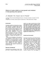
on SD-6K in June 2006 are illustrated in figure
08. From this interpretation, it was decided to
set a plug downhole to isolate water producing
from below 2,927 mTVDSS. In this particular
case the shut-off produced water zone was
unsuccessful due to limitations of downhole
isolation equipment but the value of the data is
beyond dispute.
In summary, having a good understanding
of the downhole performance through the
results of MPLT work will improve production
management and with the correct balance of
data acquisition, improved value.
T.V. Xuân / VNU Journal of Science: Earth and Environmental Sciences, Vol. 31, No. 1 (2015) 49-66
59
Figure 8. MPLT interpretation results conducted on SD-6K.
4.4. Reservoir monitoring
Interference testing may be undertaken in
certain cases to determine connectivity between
wells for better water-flooding management.
Pressure surveys conducted during long
term shut-in for determining reservoir pressure.
These long term pressure surveys not only have
been carried in producers but also have been
carried out in injection wells to determine
reservoir oil-water contact.
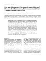
Tracer material has been and will continue
to be injected into the new injection wells to
improve the understanding of water flow
through the reservoir. Improved understanding
of water flow patterns in the reservoir will
assist in designing injection programs to
maximize oil recovery.
Tracer analysis has been conducted on
samples taken directly from well head to detect
injector to producer interactions and water
breakthroughs. Samplers have been installed on
the producing wells to facilitate capturing water
samples for the tracer survey program.
Produced water samples will be sent to the lab
regularly for analysis. Any changes in water
composition will be observed by conducting
Tracer and Chemistry analysis routinely.
Tracers were injected into injectors and their
movement analysis in the basement reservoir
has been summarized on figure 9.
Injection wells will be ramped up and the
pressure response monitored in offset wells to
increase understanding of reservoir connectivity
in order to optimize production and injection
rates.
Periodic fluid samples will be obtained to
determine any changes in fluid composition and
PVT parameters.
60
T.V. Xuân / VNU Journal of Science: Earth and Environmental Sciences, Vol. 31, No. 1 (2015) 49-66
Figure 9. Tracer movement analysis results.
4.5. Production technology diagram updating
and revising
The production target is under saturated oil
in fractured basement reservoir, no bottom
water aquifer, low gas oil ratio (GOR), the main
energy resources are fluid and rock expansion
really low and in fact in order to maintain the
reservoir (above the bubble point pressure) the
sea water injection method has been applied [3].
From study in water injection in SD oilfield
(no strong water drive) there are at least 9
injectors which located by belt model (figure
10, 11).
The study results also showed out appropriate
time and flow rate of injectors as follow:
Star injection after 06 months of production;
Drilling at least 03 injectors in first year;
Late injection could decrease cumulative
production;
Injection by belt model;
Injectors design (figure 10):
Injection @ the depth below 3,500 m deep,
The well orbit parallel to reservoir slope,
To avoid direct inject to producers.
Figure 10. The density of injector.
T.V. Xuân / VNU Journal of Science: Earth and Environmental Sciences, Vol. 31, No. 1 (2015) 49-66
61
Layout of injection wells
Figure 11. An example of injectors.
4.6. Predicting the water invasion level to
reservoir
The water invasion level to reservoir should
be predict based on data of formation water
volume, reservoir rock characteristics, reservoir
heterogeneous, hydraulic conductivity, density
and distribution of faults and fractures.
Particularly, based on scenario with
production accumulation from 251 ÷ 257
MMBO, averaging after 1,300 ÷ 1,800 days
water intrusion phenomenon seams began to
influx and gradually increase over time, to
about 5,200 days the production water ratio
increase reaches to the critical value, fractional
water cut (FWCT) are # 80% (figure 12).
Figure 12. Predicting for time and velocity of water influx .
62
T.V. Xuân / VNU Journal of Science: Earth and Environmental Sciences, Vol. 31, No. 1 (2015) 49-66
Figure 13. Predicting for flow rate and water cut variation.
Besides it, the production history also
shows there are contrary correlation over time
between flowrate and water cut ratio, in fact in
the case there is no appropriate impact
measurements applied, usually after 3,350 days
from first oil, the water influx have risen to
very high fraction, accounting for most of the
production content > 65%, the flow of the main
product (oil) dropped below a critical economic
value, # 350bbls/ day (figure 13).
4.7. Proposed solution for water influx prevention
Once the reservoir is water invaded, the
invasion velocity usually increasing quickly,
causes many consequence such as overload
water treatment system, consume high
chemicals, environment impact, and over all
decreasing cumulative production, erroneous
cumulative production prediction…Therefore
determine the instant and long term solutions to
prevent water influx are quite imperative.
4.7.1. Instant solutions to prevent water
invasion
1rst solution: reducing the flow rate: at SD
oil field by applied this solution the water cut is
initially controlled (figure 14). When water cut
began to occur, the flow rate is decreased
(choke reducing) appropriately, the water cut
always maintain at 0% until the well is abandon
and bring more 8% cumulative production from
each individual well.
Figure 14. Decreasing flow rate to control water cut.
T.V. Xuân / VNU Journal of Science: Earth and Environmental Sciences, Vol. 31, No. 1 (2015) 49-66
2nd solution: revising the production
regime and appropriate injection (figure 15)
The producers should regular spread out in
all reservoir area in order to balance the
63
pressure decrease of producers, the injectors
chosen when the water cut of closest producer
do not suddenly increasing.
Figure 15. Revising the production and injection regime.
Figure 16. Installing water plug.
64
T.V. Xuân / VNU Journal of Science: Earth and Environmental Sciences, Vol. 31, No. 1 (2015) 49-66
3rd solution: based on MPLT, to determine
the water influx zone and install the water plug
backs to isolate water produced zone or
fractures.
An example of MPLT (figure 16) showed
the water produced # 96% from zone 2 deep
down. After water plug back is installed, the
produced water decreased from 90% down to
60%.
4.7.2. Long term prevent solution
Reservoir management of the SuTu
Complex reservoirs will allow to drainage
efficiently and help identify un-depleted areas
for further development and maximize
recovery. Close monitoring of each well is vital
for optimal reservoir management. Reservoir
pressure data will be used in reservoir
simulation to assist in history matching and
therefore improve confidence in models and
allow for improved planning of development
wells and to improve reliability of production
forecasts.
The oil zone of the SuTuDen field has a low
bubble point and in this area gas cap formation
and production are not a matter; the reservoir
pressure in these areas will be maintained above
the bubble point pressure by using water
injection to provide optimal pressure
maintenance. The optimum reservoir pressure
will be determined through reservoir simulation
studies and performance analysis. This target
will be reviewed periodically and adjusted as
needed as additional performance data and
analysis is available [4].
Injection volumes and production volumes
will be controlled to optimize the reservoir
pressure and maximize recovery (figure 16).
The impact of water break-through may be
minimized through work-over programs such as
plug backs, sidetracks and re-completions.
Figure 16. Layout of producers and injectors.
T.V. Xuân / VNU Journal of Science: Earth and Environmental Sciences, Vol. 31, No. 1 (2015) 49-66
5. Conclusions and recommendations
Study results have proved all formation
water, injection water and mudlosses were
present in produced water. Among them,
formation water dominantly contributed about
two thirds proportion to produced water of SD
field generally. However, their proportions were
timely dependent and varied from well to well.
The impact of water break-through may be
minimized through work-over programs such as
plug backs, sidetracks and re-completions.
Depend on field development, the causes,
origins, direction of water invasion need to
determined and clarified. Aquifer modeling
need to build up in order to installing and
applying appropriate technical solution such as
reservoir monitoring, well observation, well
test, update field designing, developing draft,
predicting mechanism of water invasion and at
last propose prevention solution (instant, long
term) for water influx.
Further study need to be conducted to
determine the origins of produced water,
especially with basement rock reservoir,
regularly update hydrodynamic model based on
reality data those come from production and
65
injection wells, determining the effective
solutions, optimization production capacity,
water injection and enhance oil recovery.
Acknowledgements
I gratefully acknowledge authors B2011-2015 VNU HCM project for supporting me to
carry out this research and Cuulong JOC for
providing the data for my paper.
References
[1] Xuan, Tran Van et al, final reports of VNU
HCM project, effects of changes in production
water concentration to recovery efficiency of
SuTuDen oilfield (ảnh hưởng của biến đổi hàm
lượng nước sản phẩm lên hiệu suất khai thác mỏ
Sư tử Đen), 2013.
[2] CLJOC reports: Well reports, SD & SV FDP,
2007.
[3] Vietnam Petroleum Institute, Determine the
source of produced water in SD SW basement
reservoir, 2007.
[4] Reservoir Engineering Group, Cuulong joint
operating company field: Block 15-1, phase 1
production & injection performance report and
future production & injection plan, 2005.
Ảnh hưởng của nước xâm nhập đến quá trình thiết kế,
khai thác thân dầu móng nứt nẻ mỏ SuTu Den
và giải pháp phòng ngừa
Trần Văn Xuân
Đại học Bách Khoa Tp Hồ Chí Minh, 268 Lý Thường Kiệt, Q 10 Tp Hồ Chí Minh
Tóm tắt: Trong quá trình khai thác dầu khí, đặc biệt trong thân dầu móng nứt nẻ có quan hệ thủy
lực với nước thành hệ, khả năng nước xâm nhập hoàn toàn có thể xảy ra. Trên cơ sở số liệu thu thập
66
T.V. Xuân / VNU Journal of Science: Earth and Environmental Sciences, Vol. 31, No. 1 (2015) 49-66
được từ thực tế hoạt động khai thác dầu, bơm ép nước tại mỏ SuTu Den, bể Cửu long, Việt nam, tác
giả đã tiến hành nghiên cứu, đánh giá ảnh hưởng của nước thành hệ lên thân dầu móng trong từng giai
đoạn từ thăm dò, thẩm lượng, phát triển đến khai thác, xác định giải pháp, công nghệ phù hợp để hoàn
thành mục tiêu nghiên cứu đã đề ra. Trong giai đoạn thăm dò, với trường hợp áp dụng cụ thể, như
giếng khoan quan trắc, giám sát mỏ, thử vỉa, cập nhật hiệu chỉnh sơ đồ công nghệ khai thác, dự báo
khả năng, mức độ nước xâm nhập vào mỏ, bài báo đã xây dựng cơ sở lý thuyết cho việc đề xuất các
giải pháp tức thời (giảm lưu lượng khai thác, điều chỉnh chế độ khai thác-bơm ép nước, cách ly những
đới có khả năng bị ngập nước) cũng như những giải pháp dài hạn (giám sát chặt chẽ động thái áp suất
của giếng khai thác, tối ưu hóa việc thiết kế khai thác-bơm ép, xác định và lượng hóa nguồn gốc của
nước sản phẩm) nhằm phòng chống hiện tượng nước xâm nhập từ đó nâng cao hiệu suất thu hồi dầu.
Từ khóa: Thân dầu móng nứt nẻ, nước thành hệ, khai thác và bơm ép, thiết bị kiểm tra khai thác
(PLT), thử vỉa bằng bộ khoan cụ (Drill Stem Test), mô hình thủy động, hàm lượng cặn và nước
(BS&W), thu hồi dầu tăng cường (EOR).
VNU Journal of Science : Earth and Environmental Sciences, Vol. 31, No. 1 (2015) 49-66
Effects of Water Invasion to Design and Production Procedure
in Fractured Basement Reservoir, SuTu Den oil Field and
Prevention Solutions
Trần Văn Xuân*
Hồ Chí Minh City, University of Technology, 268 Lý Thường Kiệt, district 10, Hồ Chí Minh city
Received 15 January 2015
Revised 09 February 2015; Accepted 20 March 2015
Abstract: During oil and gas production processes, especially in fractured basement reservoir
those related to formation water, the ability of water invasion is quite possible. Based on realistic
production and injection activities at SuTuDen oil field, CuuLong Basin, Vietnam, the author
researched, evaluated the effects of formation water to oil and gas bearing fractured basement
reservoir which each exploration, appraisal, development and production stage accordingly,
determined the solution, appropriate technology to attain the targets. In exploration stage, early
detected the connate water appearance would guide to discover the petroleum accumulation or
avoid drill the dry holes, determine the initial oil water contact which serving for appraisal well
design as well could be the foundation to estimate the hydrocarbon initial in place. In
development, production stages, in the case particularly methods applied, such as well observing,
reservoir monitoring, formation testing, production technology diagram updating and revising,
water invasion possibility, level predicting to reservoir, since then build up the theories in order to
propose the instant solutions (reducing flow rate, adjusting production –water injection regime,
isolating potential water influx) as well as long term solutions (monitoring pressure behavior of
production well closely, optimizing production-injection design, determining and quantifying the
origins of production water) to prevent and protect water invasion hence increasing oil recovery
efficiency.
Keywords: Fractured basement reservoir, formation water, production and injection, MPLT, DST,
hydrodynamic model, BS & W, EOR.
1. Introduction∗
(figure 1, 2). With the fact that oil and gas
production in fractured basement reservoir of
STD oil field, CuuLong Basin Vietnam has
been showed out, in all cases there is very high
possibility of formation water invaded.
The SD SouthWest basement reservoir has
discovered in October 8, 2000 by wildcat well
SD-1X. It is the largest and the main producing
reservoir of SuTuDen & SuTuVang complex
which located on block 15-1, Cuu Long basin
The main problem in exploration and
production is besides reusing the energy of
aquifer (especially in primary recovery) but also
try to minimize the worse effects to production
_______
∗
Corresponding author. Tel.: 84-903700770.
Email:
49
50
T.V. Xuân / VNU Journal of Science: Earth and Environmental Sciences, Vol. 31, No. 1 (2015) 49-66
processes. Depend on specific stages of field
development, every ones who involve to
reservoir management, production operation
need to apply appropriate methods, technology
in order to reach the planned targets.
Figure 1. Location of SD and SV complex .
Figure 2. Structure of SD SW basement reservoir.
T.V. Xuân / VNU Journal of Science: Earth and Environmental Sciences, Vol. 31, No. 1 (2015) 49-66
2. General of formation water in SD oil field
2.1. Characteristics of formation water
The computational results have illustrated
that formation water is the dominant water
contributes to produced water; hence, it is
essential to inquire further research into its
nature and origin. The data computation by
linear mixing model has also given an
optimized chemical profile of water source and
it is assigned at formation water. The calculated
chemical profile allows characterizing its nature
and understanding more about the origin of
formation water.
Previous studies on hydrocarbon in
basement rocks in Cuulong basin have
concluded that most basement oil is originated
and formed in continental environments. Before
Oligocene-Miocene subsidence time, the
basement reservoir was once exposed to the
surface, in which filled water may come from
sources such as ground water, lakes, lagoons,
marshes and so on. Water contribute to aquifers
during this time would be meteoric water or
mixtures of meteoric water and saline or
brackish water of coastal environment (table 1).
Calculated formation water has its chloride
contents as low as 1,878 mg/l and total
dissolved solids (TDS) of about 3.4 g/l; this
range is similar to characteristics of fresh
brackish water. This allows suggesting that
water contributes to basement reservoir is an
ancient aquifer which was buried during
Oligocene-Miocene subsidence time; the
aquifer might originally contain mixtures of
meteoric water and seawater [1].
Preliminary remarks have suggested that
SD-2K water sample collected from SD-2K
well during production may be most favorably
considered to be representative of formation
water in the fractured basement reservoir.
However, the water sample may have been
contaminated with drilling mud loss during the
first development drilling campaign of SD1K÷SD-7K wells. The linear mixing model
computation have given the result of
approximate 3% brines contaminated in SD-2K
water sample.
This result turns out to be another approach
to estimate concentrations of other components
in formation water by subtracting their contaminated
quantities from SD-2K water sample.
Table 1. Chemical profile of formation water by optimized computation
SD-2K
Brine
Well 1K
Formation Water
Chloride
(mg/l)
6,458
154,560
3,465
1,878
Bromide
(mg/l)
2.16
69.25
5.20
0.09
51
Sulfate
(mg/l)
69.13
1,856.00
209.00
13.87
Sodium
(mg/l)
4,004.13
96,221.00
1,451.00
13.87
Total Ions
(meq/l)
367.40
8,792.60
313.30
106.78
TDS
(g/l)
10.80
259.07
6.13
3.40
Table 2. Potassium, Calcium, Magnesium concentration in formation water
SD-2K
Potassium (mg/l)
165.32
Calcium (mg/l)
30.60
Magnesium (mg/l)
39.51
Brine
Well 1K
Formation Water
1,868.00
306.00
112.70
1,104.00
616.00
N/A
1,281.00
9.12
1.11
52
T.V. Xuân / VNU Journal of Science: Earth and Environmental Sciences, Vol. 31, No. 1 (2015) 49-66
The estimated concentrations of some
cations by subtraction of contaminants in
formation water are given in table 2; Potassium
and Magnesium concentrations are proved to be
reasonably
estimated,
but
Calcium
concentration is estimated negative due to its
surprising low level in SD-2K water sample.
Water in buried aquifer usually has Calcium
concentration much higher than its own
Magnesium concentration; Calcium and
Magnesium have the same range only in deep
buried depth. If it is the case, SD-2K water, and
then formation water, may flow up from deeper
depth of basement reservoir; however, only one
water sample of SD-2K is not representative
enough to draw any conclusion.
The other water samples, which can be
considered to be approaching to formation
water in basement reservoir, are some produced
water samples taken in production well 1K.
These water samples have most solute chemical
components with about half quantities of those
in SD-2K water sample, and these are the
poorest solute content among all produced
water samples, however, they still have
Calcium concentration higher than in SD-2K
water sample. It is still interesting question on
unknown reason of lacking Calcium in SD-2K
water sample.
Despite original composition before
burying, formation is expected to have very
little quantities of Magnesium and Sulfate due
to water-rock interaction [2]. The rather high
concentration of Sulfate in produced water of
well 1K indicate that it also contains a
significant amount of injected water or drilling
fluid, so calculated chemical profile of
formation water would be containing chemical
components of significantly lower quantities
than that of 1K produced water sample [1].
This is the fact that validates appropriateness
of the optimized chemical profile of formation
water. In conclusion, the optimized chemical
profile of formation water is in good agreement
with geological settings and paleo-environment
of Cuulong basin, it is also appropriate to
observation chemical data of produced water.
2.2. General contribution of water sources to
produced water
Data computational results have proved
all formation water, injection water and
mudlosses were present in produced water;
however, their proportions were timely
dependent and varied from well to well. The
computed proportions of water sources to
produced water are plotted figure 3, solid lines
are moving averaged by time.
Figure 3. General contribution of water sources to produced water.
T.V. Xuân / VNU Journal of Science: Earth and Environmental Sciences, Vol. 31, No. 1 (2015) 49-66
Generally, about two thirds or more
proportion (figure 3 and table 3) of produced
water is derived from formation water during
acquisition time of water samples using in this
study. It is likely expected that formation water
would contribute with a greater proportion to
the volume of reservoir water body.
Before April 2006, produced water in
almost all area (MPA and SD-6K/7K/18K) was
dominantly contributed from formation water
with ratio of around 75% or higher. Injected
water contribution reached its high magnitude
during May and Jun 2006, then dropped and
increased slightly again, and have had a trend of
decreasing recently (till March-2007). These
behaviors of injected water, of course, always
accompanied with the change of formation
water contribution but in opposite direction. All
these described water dynamics would be
related to water injection performance of SD
field in previous time (figure 4).
The sharp increase of injected water
contribution to produced water from April to
July 2006, and then dropped immediately after
that, was agreeably associated with the
intensive injection time from July to December
2005 and the later shut-in and drops of water
injection (figure 4). April 2006 was also the
time that almost tracers started to be observed
53
simultaneously and regularly in production
wells. This indicates an average time of around
8 months for water movement from injector to
producer, quite accordance with data
records by tracer movements (table 3).
The highest contribution of injected water
to produced water occurred in well 4K located
in the center of MPA. Well pressure
interference observation also shown that
WHFP (Well Head Flowing Pressure) on
well 4K immediately stopped decreasing and
was stabilized as a result of water injection
restart on 12 December 2005 in wells 2I, which
is the most intensive injection, its WHFP was
also dropped sharply when water injection in
wells 12I and 2I were shut down and increased
when water injection on these two wells was
back online during 6-9 September 2006.
However, well 4K received tracer from well
2I and 9I during January to October 2006,
indicating that 4K produced water was
supported directly from these two injectors.
The greatest contribution of formation
water to produced water was observed in well
1K, where injected water was the lowest one.
This lowest contribution of injected water is
agreeable with tracer movement observation no tracer was detected during production time
in well 1K [3].
Figure 4. Total injection performance in SD field.
54
T.V. Xuân / VNU Journal of Science: Earth and Environmental Sciences, Vol. 31, No. 1 (2015) 49-66
Table 3. Tracer movement observation and its duration
Date\Well
7-Sep-05
20-Sep-05
28-Oct-05
29-Oct-05
24-Jan-06
8-Feb-06
25-Feb-06
1-Apr-06
3-Apr-06
6-Apr-06
10-Apr-06
14-Apr-06
16-Apr-06
18-Apr-06
19-Apr-06
26-Apr-06
28-Apr-06
1-May-06
3-May-06
7-May-06
9-May-06
11-May-06
15-May-06
18-May-06
19-May-06
29-May-06
1-Jun-06
5-Jun-06
9-Jun-06
25-Jun-06
5-Jun-06
10-Jun-06
17-Jun-06
23-Jun-06
28-Jun-06
2-Aug-06
22-Aug-06
4-Sep-06
18-Sep-06
3-Oct-06
16-Oct-06
3K
4K
5K
184
197
6K
6Kst
7K
17K
18K
16I
Maker 2I 8I 9Ist 1
2Ist 13Ist
235
235
323
218
234
270
392
399
403
404
405
407
409
415
417
420
422
426
392/271(?)
396/274(?)
395/274
399/278
285
288
417/296
417/301
417/307
430
434
448
275
434
437
444
448
451
455
459
475
490
546/425
560/439
575/454
588/467
308
318
331
364
369
376
382
387/388
392/393
412/413
425
439/440
454/455
467/468
485
331
335
339
355
485/365
490/370
497/377
503/383
508/388
513/393
533/413
546/426
560/440
575/455
588/468
T.V. Xuân / VNU Journal of Science: Earth and Environmental Sciences, Vol. 31, No. 1 (2015) 49-66
Two
areas,
which
have
weak
communication, SW: 7K/18K and NE: 17K
has received the greatest contribution of
mudlosses in proportions of produced water.
Wells 16I and 4K also had significant
proportion of drilling fluid in produced water; it
is likely a result from hydro-dynamical
communication with other wells in SD field.
In conclusion, magnitudes of calculated
water source contribution to produced water
in SD field correspond with injection and
production data. Their behaviors are also
confirmed by tracer movement observations
both in spatial movements and moving
durations. The contribution proportions of water
sources to produced water, which were highly
time dependent and varied spatially, indicated
that their water amounts are only mixing in
limited volumes or mixing locally in other
words.
2.3. Anomalies in 7K produced water samples
It can be reminded that there are some
outlier points that are not enclosed by the
triangle of three end-members: injected water,
drilling fluid and formation water [3]; these are
the representative points for some 7K produced
water samples. These are really anomalies that
cannot be expressed by the linear mixing
model; and they need be examined in details.
Chemical compositions of these 7K produced
water samples are given in table 4.
All 7K produced water samples have very
high total dissolved solids which are equal to
or higher than that of seawater while their
Bromide contents are lower than. SD-7K-1
water sample also has Sulfate content as high
as that of seawater while other soluble
components are much higher than. It is
noticeable that 7K produced water samples have
pH lower than almost all produced water sample.
Table 4. Chemical compositions of 7K produced water samples
Sample Name
SD-7K-1
7K-bst-2
7K-bst-3
7K-bst-4
Acquisition Date
9-May-06
4-Sep-06
20-Sep-06
19-Feb-07
Total Dissolved Solids (g/l)
71.6
82.9
56.8
30.55
pH
6.9
6.9
6.8
7.1
24,367
30,089
20,214
9,463
493
305
221
239.6
Magnesium Mg (mg/l)
2,277
213
138
97.6
2+
1590
3372
2931
1,912.8
-
40,084
47,275
31,976
18,154
-
+
Sodium Na (mg/l)
+
Potassium K (mg/l)
2+
Calcium Ca (mg/l)
Chloride Cl (mg/l)
55
Bromide Br (mg/l)
91.8
61.6
37
40.39
Sulfate SO4 2- (mg/l)
2,641
796
774
371.8
Bicarbonate (mg/l)
300
505
375
110
Total Ions (meq/l)
2,781.7
4,731.2
3,855.7
2,434.9