Topic 6 AC circuit analysis topic a6
Bạn đang xem bản rút gọn của tài liệu. Xem và tải ngay bản đầy đủ của tài liệu tại đây (173.64 KB, 41 trang )
Solve problems in single and threephase low voltage circuits
Part A
Topic 6: AC Circuit
Analysis
AC Circuit Analysis: Impedance
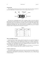
Practical AC circuits often consist of resistive,
inductive, and/or capacitive components in many
varying combinations.
These components will combine to produce an
overall opposition to the flow of AC current.
This total opposition to the flow of AC current is
called IMPEDANCE.
Symbol Z, measured in Ohms (Ω)
–
Impedance may consist of any combination of resistance,
inductive reactance, and / or capacitive reactance.
AC Circuit Analysis: Ohm’s Law for AC
VS
IS
Z
Ohm’s Law – AC circuits
AC Circuit Analysis: Determining
Impedance
Determining Impedance involves two
methods, depending upon the type of circuit
being analysed.
–
For SERIES circuits: requires the use of the impedance
triangle
AC Circuit Analysis: Determining
Impedance
Z
X
Impedance
(Ø)
Phase Angle
Reactance
R
Resistance
Z = √(R2 + X2)
Series Circuits Only
AC Circuit Analysis
Series Circuits
AC Circuit Analysis: Series R-L Circuit
Determine the following:
R = 25Ω
L=0.15H
•Impedance Z
•Supply current IS
VS=230V
ƒ= 50Hz
•Voltage across Resistor VR
•Voltage across Inductor VL
•Phase Angle Ø between VS
and IS
AC Circuit Analysis: Series R-L Circuit
Process
Step 1: Determine Inductive reactance XL
Step 2: Determine Impedance Z
XL=2πƒL
Z=√(R2+X2)
Step 3: Determine the supply current
IS=VS / Z
AC Circuit Analysis: Series R-L Circuit
Process
Step 4: Calculate voltage drops (Ohm’s law)
VR = IS x R
VL = IS x XL
Step 5: Draw the phasor diagram, use
phasor addition to determine position of VS,
and measure phase angle Ø
AC Circuit Analysis: Series R-L Circuit
Process – Phasor Diagram
VL
C-I-V-I-L
VS Check that VS measured
here matches the actual
value for VS for the circuit
Step 6: Measure the phase
angle (Ø) between VS and
IS
VR
IS (reference ~ series circuit)
AC Circuit Analysis: Series R-L Circuit
Process
Final Answer
IS is … Amps and LAGS/LEADS the VS by …oE
Note: We always describe what the CURRENT is doing with
respect to the VOLTAGE, irrespective of which is the
reference.
AC Circuit Analysis: Series R-L Circuit
Answers to example
XL = 47.12 Ω
Z = 53.3 Ω
IS = 4.32 A
VR = 108 V
VL = 204 V
VS = ~230 V
Ø = 62oE Lag
Final answer: IS is 4.32A and LAGS VS by 620E
AC Circuit Analysis: Series R-L Circuit
Determine the following:
R = 100Ω
L=0.25H
•Impedance Z
•Supply current IS
VS=230V
ƒ= 50Hz
•Voltage across Resistor VR
•Voltage across Inductor VL
•Phase Angle Ø between VS
and IS
AC Circuit Analysis: Series R-L Circuit
Answers to example
XL = 78.5 Ω
Z = 127.2 Ω
IS = 1.81 A
VR = 181 V
VL = 142 V
VS = ~230 V
Ø = 38oE Lag
Final answer: Is is 1.81A and LAGS VS by 380E
AC Circuit Analysis: Series R-C Circuit
R = 68Ω
C = 100μF
VS=230V
ƒ= 50Hz
The process for analysing a Series R-C circuit is exactly the same
as for a series R-L, except that the capacitive reactance (XC)
formula is used instead of the inductive reactance (X L) formula.
AC Circuit Analysis: Series R-C Circuit
Process
Step 1: Determine Capacitive Reactance XC
Step 2: Determine Impedance Z
IS=VS / Z
Step 4: Calculate voltage drops (Ohm’s law)
Z=√(R2+X2)
Step 3: Determine the supply current
XC=1 / 2πƒC
V R = IS x R
V C = I S x XC
Step 5: Draw the phasor diagram, and measure
phase angle Ø
AC Circuit Analysis: Series R-C Circuit
Process
VR
IS (reference ~ series circuit)
Step 6: Measure the phase
angle (Ø) between VS and
IS
C-I-V-I-L
VC
VS
Check that VS measured
here matches the actual
value for VS for the circuit
AC Circuit Analysis: Series R-C Circuit
Answers to example
XC = 31.83 Ω
Z = 75.1 Ω
IS = 3.06 A
VR = 208 V
VC = 97.4 V
VS = ~230 V
Ø = 25oE Lead
Final answer: Is is 3.06A and LEADS VS by 250E
AC Circuit Analysis: Series R-C Circuit
R = 22Ω
C = 33μF
Determine the following:
•Impedance Z
•Supply current IS
VS=230V
•Voltage across Resistor VR
ƒ= 50Hz
•Voltage across Capacitor VC
•Phase Angle Ø between VS
and IS
AC Circuit Analysis: Series R-C Circuit
Answers to example
XC = 96.46 Ω
Z = 98.94 Ω
IS = 2.32 A
VR = 51.0 V
VC = 223.8 V
VS = ~230 V
Ø = 77oE Lead
Final answer: Is is 2.32A and LEADS VS by 770E
AC Circuit Analysis:
Series R-L-C Circuit
R = 50Ω
L=0.25H
C = 150μF
VS=230V
ƒ= 50Hz
Due to the nature of the two reactive components, the inclusion of the
capacitor will produce a capacitive reactance that will act to CANCEL
out the inductive reactance produced by the inductor (or vice-versa).
The result will be a net reactance (X).
X = XBigger – XSmaller
AC Circuit Analysis: Series R-L-C
Circuit Process
•
Step 1: Determine Inductive reactance XL
XL=2πƒL
Step 2: Determine Capacitive Reactance XC
XC=1 / 2πƒC
Step 3: Determine net reactance X
X = XBigger - XSmaller
Step 4: Determine Impedance Z
Z=√(R2+X2)
Step 5: Determine the supply current
IS=VS / Z
Step 6: Calculate voltage drops (Ohm’s law)
VR = I S x R
VL = I S x X L
VC = I S x X C
Step 7: Draw the phasor diagram, measure the phase angle Ø
AC Circuit Analysis:
Series R-L-C Circuit - Phasor Diagram
VL
C-I-V-I-L
VR+L
VS
Check that VS measured
here matches the actual
value for VS for the circuit
IS (reference ~ series circuit)
C-I-V-I-L
VR
VC
Step 7: Measure the phase
angle (Ø) between VS and IS
AC Circuit Analysis: Series R-L-C
Circuit
Answers to example
XL = 78.5 Ω
XC = 21.2 Ω
X = 57.3 Ω
Z = 76.0 Ω
IS = 3.03 A
VR = 152 V
VL = 238 V
VC = 64.2 V
VS = ~230 V
Ø = 49oE Lag
Final answer: Is is 3.03A and LAGS VS by 490E
AC Circuit Analysis
Parallel Circuits