Technician Guidelinesfor Antilock Braking Systems
Bạn đang xem bản rút gọn của tài liệu. Xem và tải ngay bản đầy đủ của tài liệu tại đây (370.28 KB, 49 trang )
■
■
■
■
■
■
■
■
■
■
■
■
■
■
■
■
■
■
■
FHWA-MC-98-008
Technician Guidelines
for Antilock Braking Systems
Air-Braked Trucks, Tractors and Trailers
Prepared for the
U.S. Department of Transportation
Federal Highway Administration
by
The Maintenance Council
Federal Highway Administration
U.S. Department of Transportation
■
■
■
■
■
■
■
■
American Trucking Associations
2200 Mill Road
Alexandria, Virginia 22314
■
■
■
■
■
■
■
■
■
■
■
■
■
■
■
■
■
■
■
Technician
Guidelines
For Antilock
Braking
Systems
Air-Braked Trucks, Tractors, and Trailers
■
■
■
■
■
■
■
■
Prepared for the
U.S. Department of Transportation
Federal Highway Administration
400 Seventh Street , S.W.
Washington, D.C. 20590
by
FHWA-MC-98-008
The Maintenance Council
American Trucking Associations
2200 Mill Road
Alexandria, Virginia 22314
(703) 838-1763
■
■
■
■
■
■
■
Technical Report Documentation Page
1. Report No.
2. Government Accession No.
3. Recipient’s Catalog No.
FHWA-MC-98-008
5. Report Date
4. Title and Subtitle
March 1, 1998
Technician Guidelines for Antilock Braking Systems
6. Performing Organization Code
7. Author(s)
8. Performing Organization Report No.
The Maintenance Council of the
American Trucking Associations
10. Work Unit No.
9. Performing Organization Name and Address
The Maintenance Council of the
American Trucking Associations
2200 Mill Road
Alexandria, VA 22314
11. Contract or Grant No.
DTFH61-93-C-00088
13. Type of Report & Period Covered
12. Sponsoring Agency Name and Address
Federal Highway Administration
Office of Motor Carrier Research and Standards
400 Seventh St., S.W.
Washington, DC, 20590
14. Sponsoring Agency Code
FHWA/HCS-10
15. Supplementary Notes
L. Minor — Contracting Officer’s Technical Representative (COTR)
16. Abstract
This manual provides generic technician guidelines for inspecting, maintaining and
troubleshooting antilock braking systems (ABSs) used on air-braked, heavy vehicles.
17. Key Words
18. Distribution Statement
ABS, air brakes, antilock braking systems,
stopping capability, stability and control,
brake inspection.
19. Security Classification (of report)
None
No restrictions. Available through the
National Technical Information
Service, Springfield, VA 22161.
Telephone: (703) 605-6000
20. Security Classification (of this page)
None
21. No. of pages
44
22. Price
PURPOSE
The purpose of this document is to provide truck technicians with general guidelines for ABS operation, maintenance,
inspection and troubleshooting. Technicians should always
consult the appropriate vehicle or component manufacturer’s
information for specific ABS procedures.
DISCLAIMER
This document is disseminated under the sponsorship of
the Department of Transportation in the interest of information
exchange. The United States Government assumes no liability
for its contents or use thereof. The contents of this document
do not necessarily reflect the official policy of the Department
of Transportation. This publication does not constitute a
standard, specification or regulation.
The Maintenance Council and the Trucking Research
Institute have made a reasonable effort to ensure the accuracy
of information contained in this publication. However, all
equipment users should satisfy themselves that the procedures
outlined herein are appropriate for their own use.
The United States Government does not endorse products
or manufacturers. Trade or manufacturers’ names appear
herein only because they are considered essential to the object
of this document.
ACKNOWLEDGMENT
The authors extend their thanks to the following organizations which contributed to the development of this document.
• American Trucking Associations’ Engineering Dept.
• The ATA Foundation
• Bendix/AlliedSignal Corporation
• Eaton-Bosch
• Federal Highway Administration
• Midland-Grau
• Rockwell WABCO
• The Maintenance Council’s ABS/EBS Task Force and
S.6 Chassis Study Group.
Technician Guidelines for Antilock Braking Systems
■
■
■
■
■
■
■
■
■
■
■
■
■
■
■
■
■
■
■
■
■
■
■
■
■
■
■
■
■
■
■
■
■
■
TABLE OF CONTENTS
I. AN INTRODUCTION TO ANTILOCK BRAKING ............
A. What is an ABS? ...............................................
B. How Do ABSs Work? .........................................
C. How Should I Drive an ABS-equipped Vehicle
During Road Tests? ...........................................
D. What Are the Features and Benefits of ABSs? .....
3
3
5
6
7
II. ABS COMPONENT DESCRIPTIONS AND
OPERATION ......................................................... 8
A. Electronic Control Unit (ECU) ............................. 8
B. Modulator Valves ............................................ 10
C. Wheel Speed Sensors ...................................... 11
D. ABS Malfunction Indicator Lamps..................... 12
E. ABS Diagnostics .............................................. 12
F. Traction Control Systems ................................. 13
III. ABS TROUBLESHOOTING, MAINTENANCE AND
INSPECTION ....................................................... 14
A. ABS Troubleshooting ......................................
1. General Diagnostic Principles .....................
2. Notes on Electrical/Electronic Connections ..
3. Error Detection Methods ............................
4. Causes of Common ABS Sensor Problems ....
14
14
19
23
25
B. ABS Maintenance and Inspection .....................
1. ABS Sensor Pickup Adjustment ...................
2. ABS Sensor Pickup Removal and Installation
3. Sensor Pickup Removal—Front Axle ............
4. Sensor Pickup Installation—Front Axle ........
5. Sensor Pickup Removal—Rear Axle .............
6. Sensor Pickup Installation—Rear Axle .........
7. Proper ABS Sensor Resistance .....................
8. Modulator Valves/Routine Inspection ..........
9. Modulator Valve Removal and Installation ..
10. Proper ABS Modulator Valve Resistance ....
27
27
27
27
27
28
28
29
29
30
30
IV. ABS SPEC’ING CONSIDERATIONS ......................... 31
V. GLOSSARY OF ABS TERMS ................................... 33
VI. INDEX ................................................................ 42
■
1
Technician Guidelines for Antilock Braking Systems
■
■
■
■
2
■
■
■
■
■
■
■
■
■
■
■
■
■
■
■
■
■
■
■
■
■
■
■
■
■
■
■
■
■
■
■
Technician Guidelines for Antilock Braking Systems
■
■
■
■
■
■
■
■
■
■
■
■
■
■
■
■
■
■
■
■
■
■
■
■
■
■
■
■
■
■
■
■
■
■
I. AN INTRODUCTION TO ANTILOCK BRAKING
This section reviews several basic antilock braking system
(ABS) concepts. When you complete this section, you should be
able to answer the following questions:
• What is an ABS?
• Why are antilock braking systems (ABSs) standard on
most new commercial vehicles?
• How does an ABS work?
• What are the major features and benefits of ABSs?
• How should I drive an ABS-equipped vehicle during a
road test?
A. What is an ABS?
Antilock braking
systems (ABSs) are
electronic systems that
monitor and control
wheel slip during vehicle
braking.
Reducing wheel slip
improves vehicle
stability and control
during braking, since
stability increases as
wheel slip decreases.
Antilock braking systems (ABSs) are electronic systems that
monitor and control wheel slip during vehicle braking. ABSs
can improve vehicle control during braking, and reduce
stopping distances on slippery (split or low coefficient of
friction) road surfaces by limiting wheel slip and minimizing
lockup. Rolling wheels have much more traction than locked
wheels. Reducing wheel slip improves vehicle stability and
control during braking, since stability increases as wheel slip
decreases.
ABSs can be applied to nearly all types of vehicles and can
be successfully integrated into hydraulic and air brake systems
(including air over hydraulic). This document applies to the
ABSs used with air brake systems on commercial vehicles.
The National Highway Traffic Safety Administration
(NHTSA) requires—through FMVSS 121, “Air Brake Systems”
and FMVSS 105, “Hydraulic Brake Systems”—that ABSs be
installed on commercial vehicles built (built meaning the official
date of manufacture) on or after:
• March 1, 1997, for air-braked truck-tractors.
• March 1, 1998, for other air-braked vehicles (trucks,
buses, trailers and converter dollies).
• March 1, 1999, for hydraulically braked trucks and
buses with gross vehicle weight ratings of more than
10,000 lbs.
The equipment requirements of FMVSS 121 specify that
ABSs on truck-tractors and full trailers must control the brake
■
3
Technician Guidelines for Antilock Braking Systems
■
■
■
■
■
■
■
■
■
■
■
■
■
■
■
■
■
■
■
■
■
■
■
■
■
■
■
■
■
■
■
■
■
■
pressures to at least one front axle and one rear axle. The ABSs
on semi-trailers and dollies must control at least one axle of the
vehicle. Additionally, the ABSs on tractors must control one of
the rear axles with two modulator valves so that the brake
pressure on one end of the axle is independent of the brake
pressure on the other end. The performance requirements of
FMVSS 121 can require an ABS on additional axles.
NHTSA defines an ABS as a portion of a service brake
system that automatically controls the degree of rotational
wheel slip during braking by:
• Sensing the rate of angular wheel rotation.
• Transmitting signals regarding the rate of wheel
rotation to one or more devices, which interpret these
signals and generate responsive controlling output
signals.
• Transmitting those signals to one or more devices
which adjust braking forces in response to the signals.
Other aspects of NHTSA’s rule stipulate that:
• ABSs on trailers be capable of being powered by the
trailer’s stop lamp circuit.
• New tractors—built on or after March 1, 1997—
provide constant electrical power to a tractor-to-trailer
electrical connector for powering trailer ABSs.
• Vehicles required to have an ABS also have a yellow
ABS malfunction indicator lamp which lights up to
indicate most malfunctions.
• The power unit’s ABS malfunction lamp be “in front of
and in clear view” of the driver. It lights when the
ignition key is first switched “on” for a bulb check.
• The ABS malfunction lamp on trailers be mounted on
the left side of the trailer, near the rear side marker
lamp. On dollies, the lamp is located on the left side
where it can be seen by someone standing about 10
feet from the lamp. The lamp lights for a short bulb
check when the vehicle is stopped and the ABS starts
receiving electrical power. This lamp will no longer be
required after February 2009.
• Air-braked tractors and trucks which tow other airbraked vehicles—built on or after March 1, 2001—
have an in-cab warning lamp which indicates
■
4
Technician Guidelines for Antilock Braking Systems
■
■
■
■
■
■
■
■
■
■
■
■
■
■
■
■
■
■
■
■
■
■
■
■
■
■
■
■
■
■
■
■
■
■
malfunctions in any towed trailer’s or dolly’s ABS. Its
location and function are the same as for the powered
unit’s ABS malfunction lamp.
• Trailer and dolly ABSs—built on or after March 1,
2001—have the equipment needed to send an ABS
malfunction signal to the towing vehicle. A towing
trailer must also be able to relay an ABS malfunction
signal from the vehicle it is towing to the vehicle
towing it.
B. How Do ABSs Work?
Electronic controls allow
an ABS to adjust brake
pressure faster and more
accurately than can
drivers.
An ABS is more effective
on slippery roads
because it tailors the
brake pressure at the
wheel to maximize
vehicle braking and
stability.
An ABS consists of several key components: electronic
control unit (ECU), wheel speed sensors, modulator valves, and
exciter rings. Here’s how these components work together:
1. Wheel speed sensors constantly monitor and send
electrical pulses to the ECU at a rate proportional to
the wheel speed.
2. When the pulse rates indicate impending wheel
lockup, the ECU signals the modulator valve(s) to
reduce and/or hold the brake application pressure to
the wheel(s) in question.
3. The ECU then adjusts pressure, seeking one which
gives maximum braking without risking wheel lockup.
4. When the ECU acts to modulate the brake pressure, it
will also (on most vehicles) turn off the retarder (if so
equipped) until the risk of lockup is over.
5. The ECU continually checks itself for proper
operation. If it detects a malfunction/failure in the
electrical/electronic system, it will shut down that part
of the ABS affected by the problem—or the entire
ABS—depending upon the system and the problem.
When this happens, the ABS malfunction lamp lights.
An ABS adjusts brake pressure much faster and more
accurately than can drivers. It’s faster because:
• electronic controls are very fast and
• ABS modulator valves are physically closer to the
brakes than is the driver’s foot brake valve.
It is more effective, too, because an ABS can tailor the brake
pressure to each wheel or set of wheels to provide maximum
■
5
Technician Guidelines for Antilock Braking Systems
■
■
■
■
■
■
■
■
■
■
■
■
■
■
■
■
■
■
■
■
■
■
■
■
■
■
■
■
■
■
■
■
■
■
braking/stability. Some vehicles also use a traction control
system in conjunction with the ABS. Traction control helps the
ABS improve vehicle traction by minimizing wheel slip on the
drive axle during acceleration. If a wheel on the drive axle starts
to slip, the traction control system automatically brakes the
wheel slightly, transferring engine torque to the wheels with
better traction. If all the drive wheels start to slip, the traction
control system may also reduce engine power.
Traction control systems are referred to by several different
names, depending on the manufacturer. These include:
• Automatic Traction Control (ATC)
• Traction Control (TC)
• Automatic Slip Regulation/Anti-Spin Regulation (ASR)
C. How Should I Drive an ABS-equipped Vehicle During Road Tests?
It is the consensus of brake experts that drivers should
brake an ABS-equipped vehicle just as they would brake a nonABS equipped vehicle.
The proper braking technique is to maintain a steady,
modulated brake application. Modulated, in this case, means
applying only the pressure required to achieve the desired
deceleration. Do not slam on the brakes to make speed
corrections or routine stops.
Brake an ABS-equipped
When operating on slippery surfaces, with or without an
vehicle just as you
ABS, it is strongly recommended that drivers depress the clutch
would brake a non-ABS
when braking. Engine braking itself can cause drive wheels to
equipped vehicle.
slip. Usually, any retarder will automatically be disabled when
the ABS is in use.
Much of what is taught about hydraulic ABSs doesn’t apply
Only apply the pressure
to air ABSs. Thus, it’s important to remember the following:
required to achieve the
• Brake as if no ABS is present, with a modulated
desired deceleration.
application as described previously.
• Unless certain that the entire combination vehicle has a
working ABS, don’t stomp on the brakes in a panic
situation—one or more wheels could lock and cause
the vehicle to jackknife. Even then, be careful because
you can still jackknife or lose control if the vehicle is
travelling too fast.
• Do not expect to feel the brake pedal pulsing or hear
strange sounds when the ABS activates on air-braked
vehicles. These vehicles do not transmit pulsing
pressure to the driver’s foot and the driver probably
will not hear the system cycling.
■
6
Technician Guidelines for Antilock Braking Systems
■
■
■
■
■
■
■
■
■
■
■
■
■
■
■
■
■
■
■
■
■
■
■
■
■
■
■
■
■
■
■
■
■
■
• Operate mixed combination vehicles (with and without
an ABS) the same way one would operate totally nonABS combination vehicles. Apply only the brake
pressure needed to achieve the desired deceleration
while ensuring vehicle stability. Monitor the
combination vehicle behavior and back off the brake
pedal, if possible, to keep the units under control.
D. What Are the Features and Benefits of ABSs?
Table 1 lists the major features and benefits offered by ABSs:
TABLE 1: ABS Features and Benefits
FEATURE
BENEFIT
Increases steering ability and vehicle stability
during braking
Control of steering, drive and trailer wheels
Reduces possibility of jackknifing and trailer
swing
Reduces tire flatspotting
Fail-safe electrical/electronic system
If the electrical/electronic system fails, the
ABS is shut off, returning the vehicle to
normal braking. On some systems, the ABS
is only shut off at the affected wheels.
Traction control
An optional feature that controls excessive
wheel spin during acceleration, reducing the
possibility of power skids, spins or jackknifes.
Self-diagnosing system
Built-in system makes maintenance checks
quick and easy.
Diagnostic tool compatibility
ABSs are compatible with industry standard
hand-held and computer-based diagnostic
tools. Blink codes and other diagnostic
schemes can also be used for
troubleshooting, if other tools are not
available.
ABS Malfunction Indicator Lamp
Informs the driver or technician that an ABS
fault has occured. The warning lamp may
also transmit blink code information. It does
not signal all possible faults.
■
7
Technician Guidelines for Antilock Braking Systems
■
■
■
■
■
■
■
■
■
■
■
■
■
■
■
■
■
■
■
■
■
■
■
■
■
■
■
■
■
■
■
■
■
■
II. ABS COMPONENT DESCRIPTIONS & OPERATION
This section describes the design and operation of ABS
components.
When you complete this section, you should understand the
purpose and function of all major ABS parts including: the ECU,
the modulator valve, the wheel speed sensor, ABS malfunction/
indicator lamp, ABS diagnostic components, and traction
control.
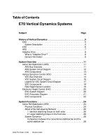
Modern antilock braking systems all feature the following
major components (See Fig. 1 on page 9 for typical system):
• Electronic Control Unit (ECU)
• Modulator Valves
• Wheel Speed Sensors (pickup and exciter)
• ABS Malfunction Indicator Lamps
• Diagnostics
A. Electronic Control Unit (ECU)
The ECU processes all ABS information and signal functions.
It receives and interprets voltage pulses generated by the
sensor pickup as the exciter teeth pass by, and uses this
* SAE J1587, Joint SAE/
TMC Recommended
information to determine:
Practice for Electronic Data
• impending wheel lock-up and
Interchange Between
• when/how to activate the ABS modulator valves.
Microcomputer Systems in
Heavy-duty Vehicle
Applications. (See Glossary
of ABS Terms for definition
of SAE.)
**SAE J1922, Powertrain
Control Interface for
Electronic Controls Used in
Medium- and Heavy-duty
Diesel On-highway
Applications.
***SAE J1939, A series of
SAE Recommended
Practices that define
architecture and protocol
for a serial control and
communications network
for various equipment
types.
■
8
The ECU connects to the following ABS components: wheel
speed sensors, ABS modulator valves, power source, ground,
warning lamps, blink code switch, J1587* diagnostic connector,
and retarder control device (usually by relay or the J1922**/
J1939*** datalink.) The ECU also makes self-diagnostic checks
during normal operation.
During braking, the ECU uses voltage pulses from each
wheel speed sensor to determine wheel speed changes. If the
ECU determines that the pulse rate of the sensed wheels
indicates imminent lock-up, it cycles the ABS modulator valves
to modify brake air pressure as needed to provide the best
braking possible.
The ECU sends signals to the ABS malfunction indicator
lamp or blink code lamp to communicate ABS faults. It also
sends signals to the retarder control to disengage the retarder
when the ABS is working. When the ABS stops modulating the
brake pressure, the ECU permits retarder use once again.
Technician Guidelines for Antilock Braking Systems
■
■
■
■
■
■
■
■
■
■
■
■
■
■
■
■
■
■
■
■
■
■
■
■
■
■
■
■
■
■
■
■
■
■
FIGURE 1: TYPICAL TRACTOR ABS SCHEMATIC
■
9
Technician Guidelines for Antilock Braking Systems
■
■
■
■
■
■
■
■
■
■
■
■
■
■
■
■
■
■
■
■
■
■
■
■
■
■
■
■
■
■
■
■
■
■
Technicians can communicate with the ECU through a
standard SAE J1587 diagnostic connector (See Fig. 1).
Technicians can read and clear fault codes stored in the ECU
and run various diagnostic tests with this connector.
The type of ECU used and its location (in-cab or frame) vary
by manufacturer and application. A detailed description of all
the different ECU types used today is beyond the scope of this
manual. Consult either the vehicle or component
manufacturer’s service information for specifics.
B. Modulator Valves
ABS modulator valves regulate the air pressure to the brakes
during ABS action. When not receiving commands from the
ECU, the modulator valve allows air to flow freely and has no
effect on the brake pressure. The ECU commands the
modulator valve to either:
• change the air pressure to the brake chamber, or
• hold the existing pressure.
ABS Modulator Valve
However, it cannot automatically apply the brakes, or
increase the brake application pressure above the level applied
by the driver.
The modulator valve typically contains two solenoids. The
modulator valve and relay valve may be incorporated into a
single unit. The modulator valve may also be separate, inserted
into the service line to the brake chamber(s) after any relay
valve, located as close as practicable to the chamber(s) itself.
When the modulator valve is separate, it has to control
more air flow and, therefore, includes two larger diaphragm
valves which are controlled by the solenoids. It usually has
three ports: the supply port, the delivery port and the exhaust
port.
• The supply port receives air from a quick release or
relay valve.
• The delivery port sends air to the brake chambers.
• The exhaust port vents air from the brake chamber(s).
Typically, when an ECU controlling a separate modulator
valve detects impending wheel lockup, it activates the solenoids
to close the supply port and open the exhaust port. When
enough air is vented to prevent wheel lockup, the exhaust valve
will close and the ECU will—depending on the situation—either:
■
10
Technician Guidelines for Antilock Braking Systems
■
■
■
■
■
■
■
■
■
■
■
■
■
■
■
■
■
■
■
■
■
■
■
■
■
■
■
■
■
■
■
■
■
■
• keep the supply port closed to maintain existing
pressure, or
• open the supply port to allow brake application
pressure to increase and repeat the cycle.
C. Wheel Speed Sensors
Exciter or Tooth Wheel
ABS Sensor Pickup
The wheel speed sensor has two main components: the
exciter and the pickup. Other components include associated
wiring and mounting equipment.
Exciter—The exciter is a ring with notched teeth. The most
commonly used exciter has 100 evenly spaced teeth, but the
number of teeth can vary depending on the system design. The
component is known by several names: sensor ring, tooth
wheel, tone ring, and exciter.
Pickup—The pickup is commonly called “the sensor.” It
contains a wire coil/magnet assembly, which generates pulses
of electricity as the teeth of the exciter pass in front of it. The
ECU uses the pulses to determine wheel speeds and rates of
acceleration/deceleration. The strength of these electrical pulses
decreases rapidly with slight increases in the gap between the
pickup and the exciter.
Wheel speed sensor location varies. It can be located
anywhere on the axle to sense wheel speed. The sensor can be
an assembly containing both the exciter and the pickup with a
fixed gap. Or, the pickup and the exciter can be mounted
separately on different parts of the axle assembly. The sensor
pickup is a sealed unit and typically of elbow or straight design.
On most ABS air-braked vehicles, the pickup is located in
the mounting flange on the wheel end. The exciter usually is
either mounted on—or integrated with—the wheel hub.
Since the output of the pickup decreases so rapidly with
slight increases in exciter-pickup gap, it is imperative that the
wheel end and sensor gap be maintained within the
manufacturer’s specification.
When the wheels of only one tandem axle have wheel
speed sensors, they are usually placed on the axle whose
wheels are most likely to lock-up first during braking. On a
tandem with a four-spring suspension, the sensors are generally
on the lead axle. On a tandem with air suspension, the sensors
are generally located on the trailing axle.
ABS configuration is defined by the arrangement and
number of sensors and modulator valves used. The most
common configurations for power units are:
■
11
Technician Guidelines for Antilock Braking Systems
■
■
■
■
■
■
■
■
■
■
■
■
■
■
■
■
■
■
■
■
■
■
■
■
■
■
■
■
■
■
■
■
■
■
• four sensors/four modulators (4S/4M),
• six sensors/four modulators (6S/4M), and
• six sensors/six modulators (6S/6M).
Common configurations for trailers are 2S/1M, 2S/2M, 4S/
2M and 4S/3M.
D. ABS Malfunction Indicator Lamps
Vehicles required to have an ABS must have ABS
malfunction indicator lamps. These lamps must be yellow and
light up when the ABS has a “malfunction that affects the
generation or transmission of response or control signals” in
the ABS.
ABS malfunction indicator lamps are not required to light up
for every type of malfunction. However, they are required to
light up for short periods of time for a bulb check whenever the
ABS starts to receive electrical power. The warning lamps for
trailers and dollies are not required to light up for a bulb check
unless the vehicle is stopped.
All trailers/dollies built on or after March 1, 1998 must
feature an external ABS malfunction indicator lamp as part of
the ABS. All new trailers must be capable of activating an in-cab
trailer warning lamp beginning in March 2001. The
ABS In-cab Malfunction
requirement for an external trailer/dolly indicator lamp expires
Indicator Lamp
in March 2009.
In-cab ABS indicator lamps are typically located on the
instrument panel. The exact location and appearance vary by
vehicle/component manufacturer. Consult the manufacturer’s
service information for specifics.
(ABS)
E. ABS Diagnostics
Although not required by law, all air brake ABSs have selfdiagnostic capability. On truck-tractors and single-unit or
straight trucks, an ABS provides this information to technicians
through the malfunction indicator lamp and/or an electronic
diagnostic tool, which plugs into an on-board diagnostic
connector. The connector is typically located inside the tractor
cab just underneath the left end of the instrument panel. It is
usually the same connector that’s used to troubleshoot
electronic engines.
Truck-tractors and trucks may also use the ABS malfunction
indicator lamp to signal stored fault information through a blink
code. Vehicles using this system have a switch to activate the
■
12
Technician Guidelines for Antilock Braking Systems
■
■
■
■
■
■
■
■
■
■
■
■
■
■
■
■
■
■
■
■
■
■
■
■
■
■
■
■
■
■
■
■
■
■
blink code system. Other ABSs may also have light-emitting
diode (LED) lamps on the ECU to indicate problems.
ABSs used on trailers sometimes have a place to connect an
electronic diagnostic tool. The connector is either on a pigtail to
the ECU, on the outside of the ECU, or inside the ECU box.
Others have either LED lamps on the ECU box or number
codes displayed inside the ECU which give diagnostic
information.
F. Traction Control Systems
Traction control systems
are designed to prevent
wheel spin in the power
mode.
Unlike an ABS, traction
control can apply the
brakes automatically.
The driver does not
need to depress the
brake pedal for traction
control to engage.
Traction control is not
required by law, but it is
a common ABS option.
Traction control systems are designed to prevent wheel spin
in the power mode. Traction control attempts to regain traction
by braking the spinning wheels, and sometimes throttling back
engine power. Unlike an ABS, traction control can automatically
apply the brakes. The driver does not need to depress the brake
pedal for traction control to engage.
Traction control electronics are integrated into the ABS ECU.
The system applies the brakes on the spinning wheel(s) when
the wheel speed sensors tell the ECU that a wheel is
accelerating at a much faster speed than the wheel on the other
end of the axle. It does this by energizing a solenoid valve,
which directs reservoir pressure to the relay valve and
simultaneously activates the modulator valves to keep air
pressure from the brake chambers. The ECU then directs the
modulator valve to open, and pulse air into the brake chamber
on the spinning wheel until wheel speed balance is regained.
On some systems, the ECU will throttle back engine power
if both wheels are spinning too fast. If all the drive wheels on a
tractor are spinning too fast, the tractor can become unstable,
spin or jackknife. Traction control is especially valuable when a
light drive wheel load might allow the wheels to spin under
power, or when a tractor is pulling multiple trailers.
■
13
Technician Guidelines for Antilock Braking Systems
■
■
■
■
■
■
■
■
■
■
■
■
■
■
■
■
■
■
■
■
■
■
■
■
■
■
■
■
■
■
■
■
■
■
III. ABS TROUBLESHOOTING, MAINTENANCE &
INSPECTION
Although an ABS generally requires no routine
maintenance, it should be checked periodically like other
components of the air brake system.
In this section, we review various aspects of ABS
troubleshooting, maintenance and inspection. When you
complete this section, you should understand:
• General ABS troubleshooting principles
• Special concerns about connector repairs
• ABS error detection methods
• Common ABS errors and causes
• General ABS component adjustment, installation and
removal procedures
A. ABS Troubleshooting
1. General Diagnostic Principles
This section describes general principles of electrical,
electronic, and air system diagnostics to provide technicians
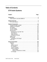
with a plan of action for ABS troubleshooting. Chart 1 on page
15 illustrates these diagnostic principles in flow chart form. The
following sub-sections—based on The Maintenance Council’s
Recommended Practice TMC RP 1406, “Basic Electrical/
Electronic Diagnostic Procedures”—cover this process in detail.
Step 1: Verify the problem or driver concern.
Establish the connection between the symptom and the
underlying cause of the problem. Use the vehicle
manufacturer’s recommended information collection methods
for verification.
Step 2: Perform preliminary checks.
Operational, visual and audio checks are generally easy to
perform, do not require the use of special tools and may result
in a quick diagnosis. This is a critical step in the diagnostic
process.
■
14
Technician Guidelines for Antilock Braking Systems
■
■
■
■
■
■
■
■
■
■
■
■
■
■
■
■
■
■
■
■
■
■
■
■
■
■
■
■
■
■
■
■
■
■
CHART 1: GENERAL DIAGNOSTIC PRINCIPLES
Begin
➤
➤
Step 1: Verify Concern
➤
Step 2: Perform
Preliminary Checks
➤
Step 3: Refer to Service
Information
➤
Step4:4:Perform
PerformChecks
Systemof
Step
Checks
Electrical, Electronic, Air Systems
➤
No
Step 5: Find and Isolate
Problems
➤
Problem
Isolated?
➤
Step 5a: Re-examine
Complaint
Yes
➤
Step 6: Repair and Verify
➤
Step 7: Clear All
Fault Codes
➤
Step 8: Implement
Preventive Measures
■
15
Technician Guidelines for Antilock Braking Systems
■
■
■
■
■
■
■
■
■
■
■
■
■
■
■
■
■
■
■
■
■
■
■
■
■
■
■
■
■
■
■
■
■
■
Step 3: Refer to service information.
Vehicle manufacturers provide service procedures which
must be followed to ensure proper repair. Training/service
information is readily available from various sources such as:
• Bulletins
• Service newsletters
• Videotapes
• Service manuals
• Manufacturers’ and dealers’ “Help Line Phone
Numbers”
• Troubleshooting guides
Be sure to confirm that the reference material is applicable
to the specific problem or vehicle being diagnosed. Also, ensure
information is current. Vehicle and supplier manufacturers’
service information—specifically bulletins and newsletters—is
very effective and may help shorten diagnosis.
Hands-on training may also be available from the vehicle/
ABS manufacturer at dealer locations or on site at the fleet. The
Brake Training Resource Directory contains a list of brake
training resources in North America. It is available from the
Office of Motor Carriers, Federal Highway Administration, 400
7th St., S.W., Washington, DC 20590, (202) 366-4009 or from
The Maintenance Council by calling (800) ATA-LINE or (703)
838-1763.
Step 4: Perform electrical, electronic and air system checks.
Systems checks found in service manuals provide a systematic
approach to identifying the probable cause of a system fault.
This step is important to properly define the correct approach
for the repair and to avoid unnecessary time-consuming
repairs. Additionally, systems checks will help to define what
the problem is not. Systems checks may require the use of original
equipment manufacturer (OEM) service tools and should isolate
a particular component in the system as a probable cause.
i. Electrical diagnostic procedures
Electrical problems are a common cause of ABS faults. It is
beyond the scope of this document to explain electrical
diagnostic procedures for all ABSs and vehicle manufacturers in
great detail. References for diagnosing electrical systems can be
readily obtained from component, vehicle, and test equipment
■
16
Technician Guidelines for Antilock Braking Systems
■
■
■
■
■
■
■
■
■
■
■
■
■
■
■
■
■
■
■
■
■
■
■
■
■
■
■
■
■
■
■
■
■
■
manufacturers. (TMC Recommended Practice 129, “HeavyDuty Vehicle Systems Wiring Checks,” is a good source of
general information on electrical diagnostic procedures.)
ii. Electronic diagnostic procedures
To diagnose an electronic system properly, specialized test
equipment approved by the electronic system manufacturer
may be required. Failure to use the correct diagnostic tool may
result in inaccurate or incomplete diagnosis or cause ECU damage.
iii. Air system diagnostics
It is beyond the scope of this document to explain air
system diagnostic procedures in great detail. However, several
TMC Recommended Practices—such as RP 619, “Air System
Inspection Procedure”—are a good source of general
information on this topic. Other references for diagnosing air
brake systems can be readily obtained from component,
vehicle, and test equipment manufacturers.
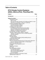
Chart 2 on page 18 is an example of a troubleshooting flow
chart for a common modulator valve problem.
Technician Tip—
If a suspect part can be
easily installed and
removed, remove and
temporarily replace it
with a known good part
to see if the problem
remains.
If the problem
disappears, reinstall the
suspect component to
see if the problem
returns. If so, replace
the suspect component.
Step 5: Find and isolate problem
For an active problem, the diagnosis should narrow and/or
eliminate possible causes. Find and isolate the faulty part of the
system or circuit by breaking the problem into smaller pieces.
For an intermittent problem, attempt to simulate/recreate the
conditions where the fault would exist. Monitor suspect circuits
and components to pinpoint the probable cause while the
problem is occurring.
Step 5a: Reexamine complaint
Review all information describing the complaint. When did
the problem occur? What conditions are present when the
symptom occurs (weather conditions, driving conditions, etc.)?
Contact the driver, if necessary, to gather more information or
to arrange a “show me” or test drive interview.
Step 6: Repair and verify
Once the suspect component is found, carefully disconnect
the old component and inspect its connections to the harness.
If the component connections are OK, temporarily connect a
known good component (without installing) to ensure the
problem is corrected.
■
17
Technician Guidelines for Antilock Braking Systems
■
■
■
■
■
■
■
■
■
■
■
■
■
■
■
■
■
■
■
■
■
■
■
■
■
■
■
■
■
■
■
■
■
■
After the problem is corrected with the known good
component, reconnect the suspect component to make sure
the problem returns. Temporarily connecting a known good
component, and then reconnecting the suspect component,
will help reduce replacement of incorrect components. If
reconnecting the suspect component does not cause the
problem to recur, thoroughly inspect the connectors and
harnessing for the cause of the problem. Reconnect the suspect
component and move (jiggle) the harness while monitoring for
the problem to return. If the problem returns with the
connection of the suspect component, permanently install the
new component.
CHART 2: SAMPLE ABS MODULATOR VALVE PROBLEM FLOW CHART
Chart 2 represents a typical troubleshooting flow chart for a common ABS modulator valve problem.
■
18
Technician Guidelines for Antilock Braking Systems
■
■
■
■
■
■
■
■
■
■
■
■
■
■
■
■
■
■
■
■
■
■
■
■
■
■
■
■
■
■
■
■
■
■
Step 7: Clear fault codes.
Clear any codes stored in the ECU identifying the problem.
Step 8: Implement any possible preventive measures.
Review the vehicle maintenance schedule for required
service intervals and perform necessary maintenance. Check
for other areas of apparent concern and notify the fleet
manager—or fix—prior to release of vehicle.
2. Notes on Electrical/Electronic Connections
The following section contains general service information
that should be considered if electrical/electronic connections
need repair during ABS servicing.
a. Wiring Termination Techniques
Termination is the process of either ending a wire or
attaching a device to be used at the end of a wire. Wiring
terminations are made in a variety of ways. Wires can be
terminated with butt splices, the application of a terminal, and
by simply “tinning” or sealing the wire’s end.
The primary considerations during a termination are
mechanical strength, vibration resistance, electrical integrity,
and environmental protection.
• Mechanical Strength—Whenever a wire is terminated,
the mechanical strength of the termination should
meet or exceed the mechanical strength of the
conductor without the termination.
• Vibration Protection—Always place conductors back in
any holding device that they were in prior to the
modification/repair or attach the conductors to the
vehicle in a manner which will prevent the conductor
from vibrating during operation.
• Electrical Integrity—The termination must be able to
fulfill the electrical needs of the circuit (for example,
current-carrying capability, minimal voltage drop).
Whenever a termination or splice is made in a
conductor, an inherent voltage drop will be present.
Special connectors are available to minimize the
voltage drop, but these connectors normally are cost
prohibitive. Terminations made carefully normally
provide an acceptable voltage drop.
■
19
Technician Guidelines for Antilock Braking Systems
■
■
■
■
■
■
■
■
■
■
■
■
■
■
■
■
■
■
■
■
■
■
■
■
■
■
■
■
■
■
■
■
■
■
• Environmental Protection—Whenever a termination is
made in a conductor which disturbs the integrity of the
insulation on the conductor, measures must be taken
to ensure that the termination is not susceptible to
moisture damage or other damage which may result
from the conductor or termination being exposed to its
normal operating environment. Additionally,
consideration must be given to the type of insulating
material being used to ensure that it has an acceptable
heat range and is compatible with the intended
environment.
• Electromagnetic/Radio Frequency Interference
Protection—The ECU contains components that can
detect radio waves and other electromagnetic “noise”
and unintenionally send false signals because of them.
To prevent radio frequency interference (RFI) and
electromagnetic interference (EMI), ABS cables contain
special shielding. When making repairs, take care to
ensure the integrity of the shielding is not
compromised.
For terminations that are made to a threaded stud which is
exposed to salt spray or other corrosive environments, a
suitable coating material should be applied to the connection to
ensure adequate service life.
Conventional Terminations—Conventional terminations are
terminations made using commercially available terminals such
as ring terminals, spade terminals, etc. Terminals of this type
are available through many different outlets.
Selection of good quality terminals is crucial to making a
dependable connection. The selection should include the
considerations mentioned in “Wiring Termination Techniques,”
as well as specific considerations about the location of the
termination on the vehicle (for example, heat exposure). Some
fleets have established specific methods for making
terminations. These methods were developed to ensure
consistent terminations which will yield an acceptable service
life. These recommendations should be followed when
applicable.
Proprietary Terminations—Proprietary terminations are
terminations made using proprietary terminals and connector
■
20
Technician Guidelines for Antilock Braking Systems
■
■
■
■
■
■
■
■
■
■
■
■
■
■
■
■
■
■
■
■
■
■
■
■
■
■
■
■
■
■
■
■
■
■
bodies. These terminations are very common on commercial
vehicles and come in a variety of configurations. Multiple
connections in one connector body are typical. Also, various
types of proprietary terminations on the same vehicle are
common. When repairing or replacing these terminations,
special techniques are needed. These techniques include tools,
special assembly methods and, many times, special training.
When servicing special connectors, use of OEM
recommended tools is critical to making a good termination.
Repair or replacement of these special terminations should not
be attempted without the specific tools recommended.
Manufacturers’ service manuals and bulletins typically detail the
techniques to be used for proper repair.
Butt Splices—A butt splice is any splice where wires are joined
together “end-to-end.” In this case, the wires may be either
twisted together and soldered, or crimped together using a
commercially available terminal. Butt splices should always be
covered with insulation and heat shrink tubing which has a
meltable inner liner or another suitable protective insulation.
The use of pressure sensitive tape is not recommended as the
tape will likely deteriorate with time.
Conductor Terminations—Terminations of conductors are
made to attach the conductor to another conductor or to a
device on the vehicle. These terminations must be carefully
made in order to provide acceptable serviceability. Attaching a
wire to another wire (not using a butt splice) is an example of a
conductor termination.
Technician Tip—
Whenever an additional
grounding point is to be
established on the
vehicle, consult the
vehicle manufacturer to
ensure that the planned
alteration does not
result in an inadequate
ground path for other
components on the
vehicle.
Terminations Without Terminals—Occasionally a wire is
terminated without a terminal to facilitate the attachment of the
wire to an accessory. If this situation is unavoidable, the wire
should be “tinned” to prevent fraying and breakage at the point
of connection. Using a heat shrink process at the end of the
wire is also acceptable.
b. Grounding Recommendations
Grounding problems occur in a variety of ways (such as
corrosion or inadequate current-carrying capacity). As a result,
grounding terminations should be coated with a suitable
material to prevent corrosion as a result of exposure to salt
spray or other corrosive environments.
■
21