GROUP 1 STRUCTURE AND FUNCTION
Bạn đang xem bản rút gọn của tài liệu. Xem và tải ngay bản đầy đủ của tài liệu tại đây (998.12 KB, 28 trang )
SECTION 3 POWER TRAIN SYSTEM
GROUP 1 STRUCTURE AND FUNCTION
1. POWER TRAIN COMPONENT OVERVIEW
Transmission
Front axle
Front drive shaft
Upper drive shaft
Center drive shaft
Rear drive shaft
Engine
Rear axle
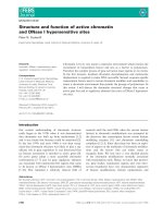
The power train consists of the following components :
şTransmission
şFront, upper, center and rear drive shafts
şFront and rear axles
Engine power is transmitted to the transmission through the upper drive shaft and the torque converter.
The transmission is a hydraulically engaged four speed forward, three speed reverse countershaft type
power shift transmission. A drum type parking brake is located on the front of the transmission housing.
The transmission outputs through universal joints to three drive shaft assemblies. The front drive shaft
is a telescoping shaft which drives the front axle. The front axle is mounted directly to the loader front
frame. The front axle is equipped with limited slip differential.
The rear axle is mounted on an oscillating pivot.
differential.
The rear axle is equipped with conventional
The power transmitted to front axle and rear axle is reduced by the pinion gear and ring gear of
differential. It then passes from the differential to the sun gear shaft(Axle shaft) of final drive.
The power of the sun gear is reduced by a planetary mechanism and is transmitted through the
planetary hub to the wheel.
3-1
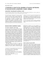
HYDRAULIC CIRCUIT
K4
M5
KV
M3
On cluster:
Regulator main pressure
KR
M1
Pressure modulation
valve(with vent valve)
Pressure relief valve
(0.15bar)
Torque converter
Pressure for
converter
M4
M2
On cluster:
Converter outlet
temperature
Pressure
holding valve
(2.0bar)
K3
K2
Pressure
reduction valve(10bar)
K1
Main pressure
valve(16+2bar)
Cooler bypass
(1.5bar)
Main pump
Heat exchanger
Filter
Safety valve
(9+1bar)
Lubrication
Oil sump
Speed
Forward
1
2
Reverse
3
4
M1
M2
X
M3
X
X
M4
X
X
M5
1
2
3
X
X
X
X
X
X
X
X : Solenoid engaged
3-2
Neutral
X
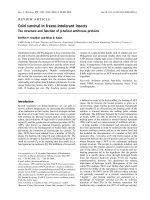
2. TORQUE CONVERTER
5
1
2
Pump
Stator
1
2
3
4
3
4
Turbine
Transmission pump
5
Input flange
The converter is working according to the Trilok-system, i.e. it assumes at high turbine speed the
characteristics, and with it the favorable efficiency of a fluid clutch.
The converter will be defined according to the engine power so that the most favorable operating
conditions for each installation case are given.
The Torque converter is composed of 3 main components :
Pump wheel - turbine wheel - stator(Reaction member)
These 3 impeller wheels are arranged in such a ring-shape system that the fluid is streaming through
the circuit components in the indicated order.
Pressure oil is constantly streaming out of the transmission pump through the converter. In this way, the
converter can fulfill its task to multiply the torque of the engine, and at the same time, the heat created in
the converter is dissipated through the escaping oil.
The oil, escaping out of the pump wheel, enters the turbine wheel and is there inversed in the direction
of flow.
According to the rate of inversion, the turbine wheel and with it also the output shaft, receive a more or
less high reaction moment. The stator(Reaction member), following the turbine, has the task to inverse
again the oil which is escaping out of the turbine and to delivery it under the suitable discharge direction
to the pump wheel.
Due to the inversion, the stator receives a reaction moment.
The relation turbine moment/pump moment is called torque conversion. This is the higher the greater
the speed difference of pump wheel and turbine wheel will be.
Therefore, the maximum conversion is created at standing turbine wheel.
With increasing output speed, the torque conversion is decreasing. The adaption of the output speed to
a certain required output moment is infinitely variable and automatically achieved by the torque
converter.
3-3
If the turbine speed is reaching about 80% of the pump speed, the conversion becomes 1.0 i.e. the
turbine moment becomes equal to that of the pump moment.
From this point on, the converter is working similar to a fluid clutch.
A stator freewheel serves to improve the efficiency in the upper driving range, it is backing up in the
conversion range the moment upon the housing, and is released in the coupling range.
In this way, the stator can rotate freely.
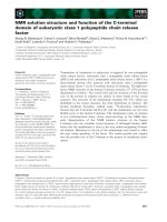
Function of a hydrodynamic torque converter(Schematic view)
TP = Torque of the pump wheel
TT = Torque of the turbine wheel
TR = Torque of the reaction member(Stator)
Pump wheel
TR
Turbine wheel
From the engine
TT
TP
To the gearbox
Starting
condition
1
1.5
Intermediate
condition
1
1
Condition shortly
before the converter
clutch is closed.
2.5
nT = 0
Machine stopped
<1.5
<2.5
nT < n engine
0
1
Reaction member
(Stator)
nT = 0.8n engine
Turbine wheel is running with
about the same speed as
pump wheel.
3-4
3. TRANSMISSION
1) LAYOUT
1
14
13
2
12
3
4
5
6
11
7
10
8
9
1
2
3
4
5
6
7
8
9
10
11
12
13
14
1st clutch(K1)
Forward clutch(KV)
Engine-dependent power take-off
2nd clutch(K2)
Reverse clutch(KR)
3rd clutch(K3)
Parking brake
3-5
Output shaft
Converter side output flange
4th clutch(K4)
Idler gear
Input shaft
Converter
Transmission pump
2) INSTALLATION VIEW
14
1
9
8
10
3
4
4
4
4
5
6
12
4
4
7
4
13
1
2
3
4
5
6
7
8
15
2
9
10
11
12
13
14
15
16
Converter
Full flow filter
Fixing plate for assy
Gearbox mounting pads
Inductive sensor-output speed
Type plate
Oil filler tube with oil dipstick
Breather
3-6
11
16
13
Electro-hydraulic shift unit
Power take-off;Coaxial;Engine-dependent
Parking brake
Suction line
Oil drain plug
Input flange
Output flange-converter side
Output flange-rear side
3) OPERATION OF TRANSMISSION
(1) Forward
ڸForward 1st
In 1st forward, FWD clutch and 1st clutch are engaged.
FWD clutch and 1st clutch are actuated by the hydraulic pressure applied to the clutch piston.
K1
KV
INPUT
K2
KR
K3
K4
OUTPUT
OUTPUT
3-7
ڹForward 2nd
In 2nd forward, FWD clutch and 2nd clutch are engaged.
FWD clutch and 2nd clutch are actuated by the hydraulic pressure applied to the clutch piston.
K1
KV
INPUT
K2
KR
K3
K4
OUTPUT
OUTPUT
3-8
ںForward 3rd
In 3rd forward, FWD clutch and 3rd clutch are engaged.
FWD clutch and 3rd clutch are actuated by the hydraulic pressure applied to the clutch piston.
K1
KV
INPUT
K2
KR
K3
K4
OUTPUT
OUTPUT
3-9
ڻForward 4th
In 4th forward, 4th clutch and 3rd clutch are engaged.
4th clutch and 3rd clutch are actuated by the hydraulic pressure applied to the clutch piston.
K1
KV
INPUT
K2
KR
K3
K4
OUTPUT
OUTPUT
3 - 10
(2) Reverse
ڸReverse 1st
In 1st reverse, REV clutch and 1st clutch are engaged.
REV clutch and 1st clutch are actuated by the hydraulic pressure applied to the clutch piston.
K1
KV
INPUT
K2
KR
K3
K4
OUTPUT
OUTPUT
3 - 11
ڹReverse 2nd
In 2nd reverse, REV clutch and 2nd clutch are engaged.
REV clutch and 2nd clutch are actuated by the hydraulic pressure applied to the clutch piston.
K1
KV
INPUT
K2
KR
K3
K4
OUTPUT
OUTPUT
3 - 12
ںReverse 3rd
In 3rd reverse, REV clutch and 3rd clutch are engaged.
REV clutch and 3rd clutch are actuated by the hydraulic pressure applied to the clutch piston.
K1
KV
INPUT
K2
KR
K3
K4
OUTPUT
OUTPUT
3 - 13
4) ELECTRO-HYDRAULIC SHIFT UNIT
A
B
C
D
E
O
M4
F
M3
M5
G
M2
H
I
M1
N
A
B
C
D
E
First and second shift valve
Solenoid pressure regulating valve
Check valve
Pressure reducing valve
Modulation valve
M
F
G
H
I
J
L
K
Pilot valve
Two-stage piston
Vent valve
Check valve
Forward shift valve
3 - 14
J
K
L
M
N
O
Reset valve
Fourth shift valve
First shift valve
Reverse shift valve
Solenoid valve
(1) The transmission control valve assembly regulates the hydraulic control circuit of the transmission.
The control valve receives electrical signals from the main controller to energize the solenoids
which direct oil to move the shift valves. When the shift valves move, oil pressure drops to start
modulation and fill the oncoming clutch pack.
(2) There are four gaskets and three plates between the transmission control valve and the housing.
Two plates are used to orifice oil to valves. The middle plate(Duct plate) is used to route oil from
the solenoids to the valves and then thru the hoses to transmission shafts. The main valve
contains pressure regulating valves, solenoid valves, shift valves, and valves for modulation.
(3) The pressure reducing valve(D) is a spring-loaded spool valve which regulates main pressure oil
by controlling flow into the control circuit. Excess oil from the control circuit flows to the torque
converter.
(4) Main pressure oil flows to the solenoid pressure regulating valve(B). The regulating valve
provides a constant oil pressure to the solenoids and is not affected by modulation. The five
solenoid valves(M) direct oil to the shift valves to provide machine direction and speed selection.
M1
M2
M3
M4
M5
Solenoid valve engages reverse shift valve(N).
Solenoid valve engages first shift valve(M).
Solenoid valve engages forward shift valve(J).
Solenoid valve engages first, second shift valve(A).
Solenoid valve engages fourth shift valve(L).
(5) The pressure regulating valve supplies a regulated pressure oil through a plate orifice to the
modulation valve(E). The modulation valve is a spring-loaded valve which controls the speed of
clutch engagement during a shift.
(6) When the first speed clutch is engaged, oil routed to the clutch pack also flows to the pilot valve
(F). The pilot valve, which is a spring-loaded shuttle valve, moves and blocks passage to the twostage piston(G). The two-stage piston is a stepping piston used to preload the modulation valve
springs to start clutch modulation at a higher pressure. In first speed, modulation starts at a lower
pressure to result in a less aggressive shift. In all other speeds, main pressure flows through the
pilot valve to the two-stage piston and preloads the modulation valve resulting in a higher starting
pressure.
(7) As modulation ends, the reset valve(K), which is a spring-loaded spool valve, moves and opens a
direct path through the modulation valve for fast clutch engagement.
(8) Two clutches have to be engaged for the machine to move. One from the directional clutch
packs either forward, reverse, or fourth. One from the speed clutch packs either first, second, or
third. Check valves(C and I) are used to prevent flow between a directional shift and a speed
shift. These check valves prevent a drop in clutch pack pressure in the engaged clutch.
3 - 15
5) SPEED CONTROL FUNCTIONAL DESCRIPTION
(1) Complete system
1
4
7
2
3
5
6
1
2
3
Transmission control unit
Transmission
Gear selector
4
5
Battery
Control valves cable
3 - 16
6
7
Inductive sensor output cable
Electro-hydraulic shift unit
(2) Description of basic functions
A specific speed range selector concept has been developed for use in wheel loaders equipped
with electro-hydraulically controlled power shift transmission, it incorporates the speed range
selector(DW-2) and micro-processor control unit(EST-17T).
This system processes all driver's instructions, such as direction of travel, selected gear as well as
the current machine speed and offers the following significant advantages:
ڸHigh adaptability to engine, machine and operation conditions through specific programming.
ڹReversing possibility through all gears.
ںEasy KD function(Semi-automatic).
ڻWaterproof, compact range selector with integrated KD button and neutral position interlock,
without any other active interlocks.
ڼShort circuit proof and overvoltage protected electrical system.
ڽMany safety features to protect against operating errors(Software).
(3) Block circuit diagram for micro-processor control unit(EST-17T)
Power supply
7 Digital inputs
8 Digital outputs
2 Frequency inputs
Micro computer
Communication and
diagnostic interface
EPROM
Safety
shifting
EST-17T
3 - 17
(4) Component description
ڸGear(speed) selector
The gear selector has been designed for
attachment to left of steering column.
Positions(Gears) 1-4 are selected by
turning, whereas the direction of travel is
selected by shifting the lever(Forward (V)
- Neutral (N) - Reverse (R)). On
transmission with 3 reverse speeds only
the gear 3R is selected on gear position
4R.
A neutral position interlock protects
against
unintentional
machine
movements during start-up. Lever
position D : Drive ; Position N : Shift lever
is locked in NEUTRAL position.
F
1
2
3
4
N
R
N
D
ڹMicro processor control unit
A. General
The short-circuit-poof and overvoltage-protected control unit must be installed in a protected
place in the driver's cab. via the by-packed buffers.
The control unit with inserted plug is splash-waterproof.
B. Direct control of solenoid valves
The solenoids of the electro-hydraulic control block at the transmission are directly controlled by
the electronics, i.e. without relays. Therefore, in normal practice just the outputs for the starter
interlock and reverse lights must be relay-controlled.
C. Gear selection
When ignition is turned on, the electronics remain in stand-by position and are ready for
operation when the lever is shifted into NEUTRAL position. Thereupon the gear can be
selected.
In general, the following applies for gear selection from NEUTRAL position : If road speed is too
high for the preselected gear(Risk of overreving), it is necessary to downshift to the lowest
permissible gear and then continue down-shifting in steps of 2.5 seconds until the preselected
gear is reached.
D. Kick down function
In gear positions 2V or 2R the 1st gear can be selected any time through slightly pushing the KD
button which is integrated in the shift lever. At proper road speed(Approx 95$ of max speed of
1st gear) up-shifting to the 2nd gear is performed automatically, however, not before 2.5
seconds.
This KD function remains in force also during reverse shifting, unless shift lever remains in
NEUTRAL position not longer than 1 second.
3 - 18
E. Passive reversing interlock
Since the gear selector DW-2 has no active reversing interlock, reversing is possible at any
time. Depending on current road speed resulting in :
ҶDirect reversing is possible at any time in gears 1 and 2(1V ؖ ؗ1R and 2V ؖ ؗ2R).
ҶThe sequence of road-speed-dependent reversing in gears 3 and 4 is as follows :
- Beyond a programmed speed limit(Normally the max speed of the 2nd gear) reversing is
performed via an immediate down-shift to the 2nd gear of the current direction of travel, a
shuttle-shift to the 2nd gear of the reverse direction of travel for 1.2 seconds, and finally upshifts to the preselected gear in steps of 2.5 seconds.
If speed drops below limit speed, reversing is performed immediately.
- Below this speed limit, reversing is performed directly, i.e. without prior down-shifts.
F. Up - shifts
If preselected gear is more than 2 gear steps beyond the currently selected gear, up-shifting is
performed in steps of 2.5 seconds.
G. Down - shifts
Down - shifts to the 2nd gear are performed immediately, even if gears are being skipped.
If 1st gear is to be selected from either the 3rd or 4th gear, it is necessary to first down - shift to
the 2nd gear for 1.2 seconds, and then continue to the 1st gear.
H. Pressure cut - off
The pressure cut - off device in the 1st and 2nd gear forward and reverse is activated by an
external positive signal(*). The transmission power-flow is interrupted as long as this positive
signal is being transmitted.
I. Cross shifts
If within the locking period of 1.2 seconds not only down but also reverse shifts are performed,
the transmission shifts to Neutral position till the end of this interval(Counted from the first
selected shifting point).
J. Direct solenoid control in NEUTRAL position
With the gear selector lever in NEUTRAL position certain transmission-specific solenoid
combinations are signalled for gear positions 1 and 2. These signals will be eliminated as soon
as max speed of 2nd gear is exceeded.
K. Detection of inductive sensor failure
The road speed is determined via the inductive sensor at the output side. Its failure will also be
assumed at a vehicle stand-still for longer than 10 seconds, although the 3rd or 4th gear is
engaged.
If the electronics have determined an inductive sensor failure, up-shifts beyond the 2nd gear are
not possible and from the 3rd and 4th gear, down-shifts can be performed only. Moreover,
reverse shifts from the 3rd or 4th gear are only possible to the 2nd gear in the reverse direction
of travel. The status inductive sensor failure will be eliminated as soon as the inductive sensor
signal can be sensed again. In this case, there is no automatic up-shifting to the preselected
higher gear(See L).
3 - 19
L. System performance in case of faults
The control unit constantly controls all inputs of the range selector as well as all outputs to the
solenoid valves. In case of inadmissible combinations(e.g. cable break, stray signals) the
electronics shift immediately to neutral condition and lock all outputs.
The same applies, if certain voltage limits are exceeded or in case of short-circuit.
This lock can be eliminated by shifting the range shift lever through the NEUTRAL position.
The same applies for the up-shift interlock after inductive sensor failure.
In case of repeated faults, it is imperative to check the machine's electrical circuit and to
exchange defective components immediately.
M. Wiring
All cable connections for solenoid valves, inductive sensor, speed range selector, electronics
and machine's electrical circuit are integrated in the compact wiring harness avoiding the
individual wiring.
This compact wiring harness is available from production in different lengths.
Ɠ A wiring system of single cables is available for prototype units in order to simplify
necessary modifications.
3 - 20
4. AXLE
1) OPERATION
ş The power from the engine passes through torque converter, transmission and drive shafts, and is
then sent to the front and rear axles.
ş Inside the axles, the power passes from the bevel pinion to the bevel gear and is sent at right
angles. At the same time, the speed is reduced and passes through the both differentials to the
axle shafts. The power of the axle shafts is further reduced by planetary-gear-type final drives and
is sent to the wheels.
(1) Front axle
1
2
3
1
Final drive
2
Differential
3
Axle
3
Axle
(2) Rear axle
1
2
3
1
Final drive
2
Differential
3 - 21
2) SECTION OF FRONT AXLE DIFFERENTIAL
A
A
4
3
2
1
5
SECTION A-A
1
2
Bevel pinion
Bevel gear
3
4
Sun gears
Shaft
3 - 22
5
Side gear(Differential)
3) SECTION OF REAR AXLE DIFFERENTIAL
A
A
4
3
2
1
5
SECTION A-A
1
2
Bevel pinion
Bevel gear
3
4
Sun gears
Shaft
3 - 23
5
Side gear(Differential)
4) DIFFERENTIAL
(1) Description
When the machine makes a turn, the
outside wheel must rotate faster than the
inside wheel. A differential is a device
which continuously transmits power to the
right and left wheels while allowing them
to turn a different speeds, during a turn.
The power from the drive shaft passes
through bevel pinion(1) and is transmitted
to the bevel gear(2). The bevel gear
changes the direction of the motive force
by 90 degree, and at the same time
reduces the speed.
It then transmits the motive force through
the differential(3) to the axle gear shaft(4).
3
2
4
1
(2) When driving straight forward
When the machine is being driven straight
forward and the right and left wheels are
rotating at the same speed, so the pinion
gear inside the differential assembly do not
rotate. The motive force of the carrier is
send through the pinion gear and the side
gear, therefore the power is equally
transmitted to the left and right axle gear
shaft.
Pinion gear
Side gear
Side gear
Axle gear shaft
Carrier
Pinion gear
(3) When turning
When turning, the rotating speed of the
left and right wheels is different, so the
pinion gear and side gear inside the
differential assembly rotate in accordance
with the difference between the rotating
speed of the left and right wheels.
The power of the carrier is then
transmitted to the axle gear shafts.
Swing
Pinion gear
Side gear
Side gear
Carrier
Pinion gear
3 - 24
Ring gear
5) TORQUE PROPORTIONING DIFFERENTIAL
(1) Function
ڸBecause of the nature of their work, 4wheel-drive loaders have to work in
places where the road surface is bad.
In such places, if the tires slip, the ability
to work as a loader is reduced, and also
the life of the tire is reduced.
The torque proportioning differential is
installed to overcome this problem.
In structure it resembles the differential of
an automobile, but the differential pinion
gear has an odd number of teeth.
Because of the difference in the
resistance from the road surface, the
position of meshing of the pinion gear
and side gear changes, and this changes
the traction of the left and right tires.
(2) Operation
ڸWhen traveling straight(Equal
resistance from road surface to left and
right tires)
Under this condition, the distances
involving the engaging points between
right and left side gears and pinion-a and
b-are equal and the pinion is balanced as
FLźa=FRźb. Thus, FL=FR, and the
right and left side gears are driven with
the same force.
Spider rotating
direction
FL
Engaging
point
Left side gear
3 - 25
FR
a b
Pinion
Engaging
point
Right side gear