GROUP 1 STRUCTURE AND FUNCTION
Bạn đang xem bản rút gọn của tài liệu. Xem và tải ngay bản đầy đủ của tài liệu tại đây (285.22 KB, 20 trang )
SECTION 4 BRAKE SYSTEM
GROUP 1 STRUCTURE AND FUNCTION
1. OUTLINE
Ɠ The brakes are operated by a pressure compensated, closed center hydraulic system.
Flow is supplied by a fixed displacement, gear type brake pump.
BRAKE SYSTEM
The fixed displacement brake pump supplies flow to service brake circuit. It flows to two
accumulator. The accumulator has a gas precharge and an inlet check valve to maintain a
pressurized volume of oil for reserve brake applications.
The front and rear brakes will operate simultaneously with only one brake pedal depressed.
The differential contains annular brake piston and double sided disk.
The brake system contains the following components:
şBrake pump
şBrake valve
şAccumulators
şPressure switches
4-1
FULL POWER HYDRAULIC BRAKE
SYSTEM
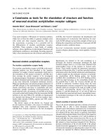
ADVANTAGES - The full power hydraulic
brake system has several advantages over
traditional brake actuation systems. These
systems are capable of supplying fluid to a
range of very small and large volume
service brakes with actuation that is faster
than air brake systems. Figure represents
a time comparison between a typical
air/hydraulic and full power hydraulic brake
actuation system.
Response time
Full power brake actuation VS
Air/Hydraulic brake actuation
1000
900
Brake torque(lbşin)
800
Full power systems can supply significantly
higher brake pressures with relatively low
reactive pedal forces. The reactive pedal
force felt by the operator will be proportional
to the brake line pressure being generated.
This is referred to as brake pressure
modulation.
Another key design feature of full power
systems is the ability to control maximum
brake line pressure. In addition, because
these systems operate with hydraulic oil,
filtration can be utilized to provide long
component life and low maintenance
operation.
Brake pressure
(Full power)
700
600
500
Brake pressure
(Air/hydraulic)
Brake torque
(Air/hydraulic)
400
300
Brake torque
(Full power)
200
100
0
1
2
Time(Seconds)
Because these systems are closed center,
by using a properly sized accumulator,
emergency power-off braking that is
identical to power-on braking can be
achieved. These systems can be either
dedicated, where the brake system pump
supplies only the demands of the brake
system or non-dedicated, where the pump
supplies the demands of the brake system
as well as some secondary down stream
hydraulic devise.
Another important note is that all seals
within these system must be compatible
with the fluid medium being used.
4-2
3
4
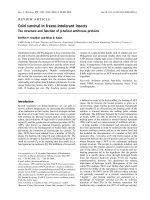
2. HYDRAULIC CIRCUIT
FRONT
24
REAR
13
13
14
16
6
BR1
BR2
M2
DS1
S1
DS2
15
S2
Return line
RCV lever
S3
10
T
P1
Steering system MCV
3MPa
N
U
P
P2
T
17
C
B
A
1
18
Return line
19
20
1
6
10
13
14
Main pump
Brake valve
Pilot supply unit
Accumulator
Pressure switch
15
16
17
18
19
A 1st pump
B 2nd pump
C Brake pump
21
Pressure switch
Pressure switch
Line filter
Air breather
Hydraulic tank
4-3
20
21
24
Return filter
Bypass valve
Axle
1) SERVICE BRAKE RELEASED
FRONT
24
REAR
13
13
14
16
6
BR1
BR2
M2
DS1
S1
DS2
15
S2
Return line
RCV lever
S3
10
T
P1
Steering system MCV
3MPa
N
U
P
P2
T
17
C
B
A
1
18
Return line
19
20
21
A 1st pump
B 2nd pump
C Brake pump
When the pedal of brake valve(6) is released, the operating force is eliminated by the force of the
spring, and the spool is returned.
When the spool removes up, the exhaust port is opened and the hydraulic oil in the piston of axles
(24) return to the tank(19).
Therefore, the service brake is kept released.
4-4
2) SERVICE BRAKE OPERATED
FRONT
REAR
13
13
14
16
6
BR1
BR2 BR2
M2
DS1
S1
DS2
15
S2
Return line
RCV lever
S3
10
T
P1
Steering system MCV
3MPa
N
U
P
P2
T
17
C
B
A
1
18
Return line
19
20
21
A 1st pump
B 2nd pump
C Brake pump
When the pedal of brake valve(6) is depressed, the operating force overcomes the force of the
spring, and is transmitted to the spool. When the spool moves down, the inlet port is opened, and
at the same time the hydraulic oil controlled the pressure level by the other spool in the brake valve
enters the piston in the front and rear axles. Therefore, the service brake is applied.
4-5
3. BRAKE PUMP
1) STRUCTURE
22
21
23
27
26
29
28
30
27
31
32,33
24
26
25
21
22
23
24
25
Splined coupling
Spacer plate
O-ring
Seal
Seal
26
27
28
29
30
Bushing
Bushing
Driven gear
Drive gear
Body
31
32
33
Cover
Spring washer
Bolt
Hydraulic pumps used for the work equipment hydraulic units on construction machinery are pressure
loaded type gear pumps. This gear pump have a maximum delivery pressure of 150kgf/cm2(2130psi).
The pressure loaded type gear pump is designed so that the clearance between the gear and the side
plate can be automatically adjusted according to the delivery pressure. Therefore, the oil leakage from
the side plate is less than that in the case of the fixed side plate type under a high discharge pressure.
Consequently, no significant reduction of the pump delivery occurs, even when the pump is operated
under pressure.
4-6
2) PRINCIPLE OF OPERATION
(1) Mechanism for delivering oil
The drawing at right shows the
operational principle of an external gear
pump in which two gears are rotating in
mesh.
The oil entering through the suction port is
trapped in the space between two gear
teeth, and is delivered to the discharge
port as the gear rotates.
Except for the oil at the bottom of the gear
teeth, the oil trapped between the gear
teeth, is prevented from returning to the
suction side with the gears in mesh.
Since the gears are constantly delivering
oil, the oil delivered to the discharge port
is forced out of the port.
The amount of discharge increases with
the speed of rotation of the gear.
If there is no resistance in the oil passage
into which the discharged oil flows, the oil
merely flows through the passage,
producing no increase in pressure.
If however, the oil passage is blocked with
something like a hydraulic cylinder, there
will be no other place for the oil to flow, so
the oil pressure will rise. But the pressure
which rises in this way will never go
higher, once the hydraulic cylinder piston
starts moving because of the oil pressure.
As described earlier, the pump produces
the oil flow, but not the oil pressure. We
can therefore conclude that pressure is a
consequence of load.
In other words, the pressure depends on
a counterpart.
Suction
4-9
Discharge
(2) Internal oil leakage
Oil leaks from a place under higher
pressure to a place under lower pressure,
provided that a gap or a clearance exists
in between.
In the gear pump, small clearances are
provided between the gear and the case
and between the gear and the side plate
to allow the oil to leak out and to serve as
a lubricant so that the pump will be
protected from seizure and binding.
The drawing at right shows how the
leaked oil flows in the pump. As such,
there is always oil leakage in the pump
from the discharge side(Under higher
pressure) to the suction side. The
delivery of the pump is reduced by an
amount equal to the pump discharge.
In addition, the delivery of the pump will
also decrease as the amount of oil
leakage increases because of expanded
radial clearance resulting from the wear of
pump parts, the lower oil viscosity
resulting from increases in the oil
temperature, and the initial use of low
viscosity oil.
e
arg
h
c
Dis
n
ctio
Su
4-10
(3) Forces acting on the gear
The gear, whose outer surface is
subjected to oil pressure, receives forces
jointing towards its center.
Due to the action of the delivery pressure,
the oil pressure in higher on the delivery
side of the pump, and due to suction
pressure, is lower on the suction side. In
the intermediate section, the pressure will
gradually lower as the position moves
from the delivery side to the suction side.
This phenomenon is shown in the
drawing at right.
In addition, the gears in mesh will receive
interacting forces.
These forces pushing the gears toward
the suction side are received by the
bearings. Since the gears are pressed
toward the suction side by these forces,
the radial clearance becomes smaller on
the suction side in the case. In some
pumps, the clearance may become zero,
thus allowing the gear teeth and the case
to come into light contact.
For this reason, an excessive increase in
the delivery pressure must be avoided,
since it will produce a large force which
will act on the gears, placing an overload
on the bearings, and resulting in a
shortened service life of the bearing or
interference of the gear with the case.
Drive gear
Suction
side
Discharge
side
Driven gear
Pressure distribution
4-9
(4) "Trapping" phenomenon of the oil
When a gear pump is rotating with the
gears in mesh as shown in the drawing at
right, in some instances two sets of gear
teeth are in mesh while in other instances
only one set of the gear teeth is in mesh.
When two sets of the teeth are in mesh
simultaneously, the oil in the space
between the meshed gear teeth will be
trapped inside-the front and rear exits will
be completely shut.
This is called the "trapping" phenomenon
of oil.
The space in which the oil is trapped
moves from the suction side to the
delivery side as the gears rotate. The
volume of the space gradually decreases
from the start of trapping until the space
reaches the center section, and then
gradually increases after leaving the
center section until the end of trapping.
Since the oil itself is non-shrinkable, a
reduction of the volume of space will
greatly increase the oil pressure, unless
some plosion in made to relieve oil
pressure. The high pressure oil will
cause the pump to make noise and
vibrate.
To prevent this, relief notches are
provided on the side plates to release the
oil to the delivery side.
As shown in the drawing at right, the relief
notches are provided in such a way that
the oil can be relieved from the tapping
space to the delivery side when the
volume of the space is reduced.
Relief notches are also provided on the
suction side to prevent the formation of a
vacuum in the space by allowing the oil to
enter the space from the suction side
when the space is reduced.
Delivery
side
Suction side
Trapping starts
The space
reaches the
minimum
Trapping ends
Fixed side plate type
Side plate
Relief notch
Pressure loaded type
4-10
Bushing
4. BRAKE VALVE
1) STRUCTURE
72
42
80
26
41
86
27
4
28
5
55
64
14
1.25
82
32
36
21
37
65
1
9
41
18
43
1.47
1.22
12
30
29
12
1.23
87
31
59
24
115
1
1.22
1.23
1.25
1.47
4
5
9
12
14
18
21
Housing
Spool
Spool
Spool
Spool
Sleeve
Sleeve
Sleeve
Spring retainer
Spring retainer
Unit WVI
Spring retainer
24
26
27
28
29
30
31
32
36
37
41
42
Reducer
Spring
Spring
Spring
Spring
Spring
Spring
Spring
Circlip
Circlip
Locking screw
Locking screw
4-11
43
55
59
64
65
72
80
82
86
87
115
Locking screw
O-ring
O-ring
Thrust ring
Shaft seal
Pedal unit
O-ring
Spring
Unit RV
Sleeve
Locking screw
2) OPERATION
P
A
M1
N
S1
T
BR1
M2
BR2
M2
DS1
BR1
DS2
S1
S3
S2
DS2
S3
BR2
S2
T
N
P
VIEW A
Port
Port name
Size
P
From main pump
M18ź1.5
N
To hydraulic tank
M18ź1.5
BR1
To service brake in front axle
M16ź1.5
BR2
To service brake in rear axle
M16ź1.5
DS1
Pressure switch stop light
M12ź1.5
DS2
Pressure switch accumulator pressure
M12ź1.5
S1
Accumulator service brake
M18ź1.5
S2
Accumulator service brake
M18ź1.5
S3
Accumulator parking brake
M16ź1.5
M2
Accumulator parking brake
M12ź1.5
To hydraulic tank
M16ź1.5
T
4-12
(1) Accumulator charging valve
The accumulator loading valve or
pressure switch-off valve has the purpose
to keep a pressure level within certain limit
values(Switch-off pressure, switch-on
pressure) in an accumulator circuit. The
switching pressure difference is approx
18% of the switch-off pressure.
S2
1
S1
3
Ɠ If actuators(N) downstream from the
pump produce a higher pressure than the
switch-off pressure of the accumulator
loading valve the accumulator circuit is
raised to this pressure level.
T
N
X
P
2
The valve consists mainly of pilot control
with pressure setting element(1), pressure
compensator(2) and check valve(3).
Switching over of pump flow from accumulator load into neutral circulation
The pump delivers into the accumulator circuit via the check valve(3) during the loading
procedure. For this the pressure is passed to the load signal side of the pressure compensator(2)
via the control line and pilot control. This throttles the pump flow until the pressure, which builds
up in the accumulator circuit, overcomes the spring force of the pressure setting element(1).
The pilot control element switches the load signal line of the pressure compensator(2) from S1 to
T. The pressure compensator(2) then switches the pump flow from P to N and the check valve(3)
closes. The loading pressure is complete and the pump flow flows with low ՠp through the
loading valve.
Switching over of pump flow from neutral circulation into accumulator load
If the pressure in the accumulator circuit decreases to the lower switching point(Adding pressure)
P is connected to the load signal chamber of the pressure compensator(2) and the pump delivers
again into the accumulator circuit.
4-13
(2) 2 circuit brake valve
The 2-circuit remotely powered braking
valve is direct controlled pressure relief
valve in 3-way design with infinite
mechanical operation.
4
2
7
2
BR1
It has a maximum pressure relief of
secondary circuits and infinite adjustability
of pressure in the secondary circuits
(Braking circuits) proportional to the
direction of the operating element(4).
1
BR2
M2
DS1
With failure of one braking circuit the
second braking circuit remains fully
functional because of the mechanical
contact of both spools(2).
SP1
3
T
5
SP2
2
1
The operating force at the pedal remains
unchanged.
The 2-circuit remotely powered brake valve consists mainly of housing(1) and control spool(2),
main compression spring(3), operating element(4) and the return springs(5) and (6).
The valve is operated via the operating element(4). It pushes the main control spring(3) against
both control spools(2). First the control edges close at channel T, afterwards the flow from SP and
BR is released in both braking circuits.
The pressure building up in the brake lines pushes simultaneously via the pilot oil drillings(7)
behind the control spool against the main compression spring(3) so that the braking
pressure(Secondary pressure) rises proportional to the operating element kept constant the
control spools(2) moves into control position and holds the controlled pressure in channels BR1
and BR2 constant. The operating force of the operating element is proportional to its deflection.
When the main compression spring(3) is unloaded the pressure springs and the control spools
move in such a way that they close SP towards BR and open BR towards T and thus close the
secondary circuits(Braking circuits).
4-14
5. BRAKE ACCUMULATOR
1) STRUCTURE
81L1-0004
(Item13)
Item
B
A
C
D
Diameter
121mm
Mounting height
151mm
Norminal volume
0.75m3
Priming pressure
50kgf/cm2
Operating medium
Oil
Operating pressure
Max 180kgf/cm2
Thread
M18ź1.5
Operating
temperature range
-30 ~ 80Ş
C
Priming gas
Nitrogen
A Fluid portion
B Gas portion
C Diaphragm
D Valve disk
2) OPERATION
(1) Purpose
Fluids are practically incompressible and are thus incapable of accumulating pressure energy. In
hydropneumatic accumulators, the compressibility of a gas is utilized to accumulate fluid. The
compressible medium used in the accumulators is nitrogen.
In braking systems, the purpose of the accumulators is to store the energy supplied by the
hydraulic pump. They are also used as an energy reserve when the pump is not working, as a
compensator for any losses through leakage, and as oscillation dampers.
(2) Operation
The accumulator consists of a fluid portion(A) and a gas portion(B) with a diaphragm(C) as a gastight dividing element. The fluid portion(A) is connected to the hydraulic circuit, causing the
diaphragm accumulator to be filled and the gas volume to be compressed as the pressure rises.
When the pressure falls, the compressed gas volume will expand, thus displacing the
accumulated pressure fluid into the circuit.
The diaphragm bottom contains a valve disk(D) which, if the diaphragm accumulator is
completely empty, closes the hydraulic outlet, thus preventing damage to the diaphragm.
(3) Installation requirements
The accumulators can be fitted in the hydraulic circuit, directly on a component or in blocks on
suitable consoles.
They should be fitted in as cool a location as possible.
Installation can be in any position.
4-15
(4) Maintenance of the accumulator
No special maintenance beyond the legal requirements is necessary.
The accumulator should be checked annually. It should be replaced if the initial gas
pressure has fallen by more than 30%(Please refer to Performance testing and
checking of the accumulator).
(5) Disposal of the accumulator
Before the accumulator is scrapped, its gas filling pressure must be reduced. For this
purpose, drill a hole through gas chamber(B) using a drill approx. 3mm in diameter. The
gas chamber is located on the side opposite the threaded port above the welding seam
around the center of the accumulator.
Ɠ Wear safety goggles when doing this job.
(6) Performance testing and checking of the accumulator
The accumulator is gradually pressurized via the test pump; until the initial gas pressure is
reached, the hydraulic pressure in the accumulator will rise abruptly. This is apparent
from gauge M. If the initial gas pressure is more than 30% below the prescribed value,
the accumulator needs to be replaced. If the measuring process needs to be repeated,
wait for intervals of 3 minutes between the individual tests. Any accumulator whose initial
gas pressure is insufficient must be scrapped following the instructions under Disposal of
the accumulator.
The amount of initial gas pressure can also be checked from the vehicle. Start the
vehicle's engine. The pump will now supply oil to the accumulators. Until the initial gas
pressure is reached, the hydraulic pressure in the accumulator will rise abruptly. This is
apparent from the gauge in the cab. If the initial gas pressure is more than 30% below the
prescribed value, that initial pressure lies outside the permissible range for at least one of
the accumulators fitted in the vehicle. This accumulator can be traced only by using the
method described above, i.e. all accumulators have to be individually tested. The
accumulator whose initial gas pressure is insufficient must be replaced and scrapped
following the instruction under Disposal of the accumulator.
M
Accumulator
Safety valve
A
B
4-16
(7) Repair work
When working on the braking system, always make sure that there is absolutely no
pressure in the system. Even when the engine in switched off there will be some residual
pressure in the system.
Ɠ When doing repair work, make sure your environment is very clean.
Immediately close all open ports on the components and on pipes using plugs.
For safety reasons the accumulators need to be replaced as a whole if damaged.
4-17
6. PRESSURE SWITCHES
1) STRUCTURE
şNormally closed
H1
şNormally open
H2
G
ş Technical data
Type
Medium
G
H1
mm
H2
mm
Adjusting range
kg/cm2
Charging
NC
Oil
M12ź1.5
55
9
50 ~ 150
Brake stop
NO
Oil
M12ź1.5
55
9
1 ~ 10
5Ź1
Max 42
Clutch cut off
NO
Oil
M10ź1.0
55
9
20 ~ 50
25 Ź 1
Max 42
Item
NC : Normally closed
NO : Normally open
4-18
Adjusting pressure Voltage
kg/cm2
V
100 Ź 10
Max 42
2) OPERATION
(1) Purpose
The pressure switches are used to visually or audibly warn the driver of the pressure within the
system.
(2) Make contact / circuit closer
The pressure switch can be fitted in the braking system or directly on one of its components.
The system pressure acts on an absorption area within the switch, making an electrical contact as
the pressure on that area is increased. The resulting current is used to activate a warning facility,
for instance.
(3) Break contact / circuit breaker
The pressure switch can be fitted in the braking system or directly on one of its components.
The system pressure acts on a absorption area within the switch, breaking an electrical contact
as the pressure on that area is increased. The current is now broken, e.g. to deactivate a
warning facility.
(4) Installation requirements
No special measures need to be taken.
(5) Maintenance of the pressure switch
No special maintenance beyond the legal requirements is necessary.
When using high-pressure cleaners on the vehicle, please make sure that the water jet is not
directed at the pressure switch(Corrosion of contacts).
(6) Repair work
When working on the braking system, always make sure that there is absolutely no
pressure in the system. Even when the engine is switched off there will be some residual
pressure in the system.
Ɠ When doing repair work, make sure your environment is very clean.
Immediately close all open ports on the components and on pipes using plugs.
Ɠ For safety reasons the pressure switch needs to be replaced as a whole if damaged.
4-19
(7) Adjusting and testing pressure switch
The adjusting screw located between the two contact plugs can be set to the desired value within
a certain range. For adjusting range, please refer to the table Technical data on the previous
page.
After making the adjustment, the adjusting screw should be secured using wax or a similar
material.
(,)
(+)
4-20
Screw